US10439867B2 - Method and apparatus for optimizing a software defined network configuration - Google Patents
Method and apparatus for optimizing a software defined network configuration Download PDFInfo
- Publication number
- US10439867B2 US10439867B2 US14/986,294 US201514986294A US10439867B2 US 10439867 B2 US10439867 B2 US 10439867B2 US 201514986294 A US201514986294 A US 201514986294A US 10439867 B2 US10439867 B2 US 10439867B2
- Authority
- US
- United States
- Prior art keywords
- network
- relative performance
- performance parameters
- configuration
- services
- Prior art date
- Legal status (The legal status is an assumption and is not a legal conclusion. Google has not performed a legal analysis and makes no representation as to the accuracy of the status listed.)
- Expired - Fee Related, expires
Links
- 238000000034 method Methods 0.000 title claims abstract description 43
- 238000003860 storage Methods 0.000 claims description 51
- 238000005259 measurement Methods 0.000 description 28
- 238000012545 processing Methods 0.000 description 25
- 102100031051 Cysteine and glycine-rich protein 1 Human genes 0.000 description 11
- 230000008859 change Effects 0.000 description 10
- 238000004891 communication Methods 0.000 description 9
- 238000010586 diagram Methods 0.000 description 9
- 230000004044 response Effects 0.000 description 7
- 230000005540 biological transmission Effects 0.000 description 5
- 230000006870 function Effects 0.000 description 5
- 238000004519 manufacturing process Methods 0.000 description 4
- 238000013507 mapping Methods 0.000 description 4
- 208000000283 familial pityriasis rubra pilaris Diseases 0.000 description 3
- 230000008569 process Effects 0.000 description 3
- 102100037084 C4b-binding protein alpha chain Human genes 0.000 description 2
- 230000003139 buffering effect Effects 0.000 description 2
- 230000000694 effects Effects 0.000 description 2
- 230000006872 improvement Effects 0.000 description 2
- 230000001902 propagating effect Effects 0.000 description 2
- 230000011664 signaling Effects 0.000 description 2
- 238000012546 transfer Methods 0.000 description 2
- 102100021503 ATP-binding cassette sub-family B member 6 Human genes 0.000 description 1
- 235000008694 Humulus lupulus Nutrition 0.000 description 1
- 238000003491 array Methods 0.000 description 1
- 230000006399 behavior Effects 0.000 description 1
- 230000001413 cellular effect Effects 0.000 description 1
- 230000001934 delay Effects 0.000 description 1
- 238000011156 evaluation Methods 0.000 description 1
- 230000008921 facial expression Effects 0.000 description 1
- 238000001914 filtration Methods 0.000 description 1
- 230000002452 interceptive effect Effects 0.000 description 1
- 239000004973 liquid crystal related substance Substances 0.000 description 1
- 238000012544 monitoring process Methods 0.000 description 1
- 238000010606 normalization Methods 0.000 description 1
- 230000003287 optical effect Effects 0.000 description 1
- 238000005457 optimization Methods 0.000 description 1
- 230000003334 potential effect Effects 0.000 description 1
- 230000001105 regulatory effect Effects 0.000 description 1
- 238000004088 simulation Methods 0.000 description 1
- 230000001360 synchronised effect Effects 0.000 description 1
- 238000012876 topography Methods 0.000 description 1
- 230000007704 transition Effects 0.000 description 1
Images


Classifications
-
- H—ELECTRICITY
- H04—ELECTRIC COMMUNICATION TECHNIQUE
- H04L—TRANSMISSION OF DIGITAL INFORMATION, e.g. TELEGRAPHIC COMMUNICATION
- H04L41/00—Arrangements for maintenance, administration or management of data switching networks, e.g. of packet switching networks
- H04L41/08—Configuration management of networks or network elements
- H04L41/0803—Configuration setting
- H04L41/0813—Configuration setting characterised by the conditions triggering a change of settings
- H04L41/0816—Configuration setting characterised by the conditions triggering a change of settings the condition being an adaptation, e.g. in response to network events
-
- H—ELECTRICITY
- H04—ELECTRIC COMMUNICATION TECHNIQUE
- H04L—TRANSMISSION OF DIGITAL INFORMATION, e.g. TELEGRAPHIC COMMUNICATION
- H04L41/00—Arrangements for maintenance, administration or management of data switching networks, e.g. of packet switching networks
- H04L41/08—Configuration management of networks or network elements
- H04L41/0895—Configuration of virtualised networks or elements, e.g. virtualised network function or OpenFlow elements
-
- H—ELECTRICITY
- H04—ELECTRIC COMMUNICATION TECHNIQUE
- H04L—TRANSMISSION OF DIGITAL INFORMATION, e.g. TELEGRAPHIC COMMUNICATION
- H04L41/00—Arrangements for maintenance, administration or management of data switching networks, e.g. of packet switching networks
- H04L41/40—Arrangements for maintenance, administration or management of data switching networks, e.g. of packet switching networks using virtualisation of network functions or resources, e.g. SDN or NFV entities
-
- H—ELECTRICITY
- H04—ELECTRIC COMMUNICATION TECHNIQUE
- H04L—TRANSMISSION OF DIGITAL INFORMATION, e.g. TELEGRAPHIC COMMUNICATION
- H04L41/00—Arrangements for maintenance, administration or management of data switching networks, e.g. of packet switching networks
- H04L41/50—Network service management, e.g. ensuring proper service fulfilment according to agreements
- H04L41/5003—Managing SLA; Interaction between SLA and QoS
- H04L41/5009—Determining service level performance parameters or violations of service level contracts, e.g. violations of agreed response time or mean time between failures [MTBF]
-
- H—ELECTRICITY
- H04—ELECTRIC COMMUNICATION TECHNIQUE
- H04L—TRANSMISSION OF DIGITAL INFORMATION, e.g. TELEGRAPHIC COMMUNICATION
- H04L67/00—Network arrangements or protocols for supporting network services or applications
- H04L67/2866—Architectures; Arrangements
- H04L67/30—Profiles
-
- H—ELECTRICITY
- H04—ELECTRIC COMMUNICATION TECHNIQUE
- H04L—TRANSMISSION OF DIGITAL INFORMATION, e.g. TELEGRAPHIC COMMUNICATION
- H04L67/00—Network arrangements or protocols for supporting network services or applications
- H04L67/34—Network arrangements or protocols for supporting network services or applications involving the movement of software or configuration parameters
-
- H—ELECTRICITY
- H04—ELECTRIC COMMUNICATION TECHNIQUE
- H04L—TRANSMISSION OF DIGITAL INFORMATION, e.g. TELEGRAPHIC COMMUNICATION
- H04L43/00—Arrangements for monitoring or testing data switching networks
- H04L43/08—Monitoring or testing based on specific metrics, e.g. QoS, energy consumption or environmental parameters
-
- H—ELECTRICITY
- H04—ELECTRIC COMMUNICATION TECHNIQUE
- H04L—TRANSMISSION OF DIGITAL INFORMATION, e.g. TELEGRAPHIC COMMUNICATION
- H04L43/00—Arrangements for monitoring or testing data switching networks
- H04L43/20—Arrangements for monitoring or testing data switching networks the monitoring system or the monitored elements being virtualised, abstracted or software-defined entities, e.g. SDN or NFV
Definitions
- the present disclosure relates to a method and apparatus for optimizing a software defined network configuration using a policy-based network performance metric.
- SDNs software defined networks
- data plane processing which includes the physical forwarding of data between endpoints in the network
- control plane processing which includes making decisions concerning which routes in the SDN are to be used to forward the data between the network endpoints.
- the topography of an SDN may change dynamically as nodes (e.g., virtual and/or physical nodes) and/or interconnecting links (virtual and/or physical) are added and/or removed from the network.
- a method and apparatus for optimizing a software defined network configuration are disclosed.
- the method determines a first network relative performance parameter for a current configuration of a network, based on respective weighting profiles associated with services for which the network carries data.
- the method determines a second network relative performance parameter for a proposed configuration of the network, based on the respective weighting profiles associated with the services for which the network carries data.
- the proposed configuration is implemented in the network when the second network relative performance parameter is greater than the first network relative performance parameter.
- a non-transitory computer-readable storage device storing a plurality of instructions which, when executed by a processor, cause the processor to perform operations.
- the operations include determining a first network relative performance parameter for a current configuration of a network, based on respective weighting profiles associated with services for which the network carries data, determining a second network relative performance parameter for a proposed configuration of the network, based on the respective weighting profiles associated with the services for which the network carries data, and implementing the proposed configuration in the network when the second network relative performance parameter is greater than the first network relative performance parameter.
- an apparatus in another example, includes a processor and a computer-readable storage device storing a plurality of instructions which, when executed by the processor, cause the processor to perform operations.
- the operations include determining a first network relative performance parameter for a current configuration of a network, based on respective weighting profiles associated with services for which the network carries data, determining a second network relative performance parameter for a proposed configuration of the network, based on the respective weighting profiles associated with the services for which the network carries data, and implementing the proposed configuration in the network when the second network relative performance parameter is greater than the first network relative performance parameter.
- FIG. 1 illustrates a block diagram of an example communication network including an example configuration selector to determine an optimal network configuration in accordance with the teachings of this disclosure
- FIG. 2 illustrates a block diagram of an example implementation of the optimal composition determination engine of FIG. 1 ;
- FIG. 3 is a block diagram illustrating example information exchanged between the example optimal composition determination engine and the example graph database of the example configuration selector of FIG. 1 ;
- FIGS. 4A-B illustrated further examples of topology information stored in the example graph database of FIG. 1 ;
- FIGS. 5A-D illustrate further example component relative performance metrics and path relative performance metrics capable of being determined by the example optimal composition determination engine of FIGS. 1-3 for different example network topologies;
- FIG. 6 illustrates an example communication network including a second example implementation of the configuration selector of FIG. 1 ;
- FIG. 7 is a flowchart illustrating an example program that may be executed to implement the example configuration selector of FIGS. 1-6 ;
- FIG. 8 is a block diagram of an example processor platform capable of executing the instructions of FIG. 6 to implement the example configuration selector of FIGS. 1-6 .
- SDNs software defined networks
- NFV network function virtualization
- SDN configurations including selection and placement of components, storage, computation facilities, and interconnections, are typically manually configured by network engineers.
- policies that act upon the networks' components are also typically manually defined. These policies manage the networks with a goal of optimizing the delivery of services within the constraints imposed by various parameters, including software lifecycles, operations support systems, business support systems, and applications.
- These manual procedures tend to be labor intensive and time consuming (e.g., not responsive in real time), and may result in less than optimal solutions due to the networks' configuration complexity.
- the present disclosure broadly describes a method, a computer-readable storage device, and an apparatus for optimizing a software defined network configuration using a policy-based network performance metric.
- an application allows a network, such as a software defined network, to self-optimize by identifying potential incremental changes to its configuration and estimating the effects of the potential incremental changes on overall network performance.
- the potential effects of a proposed incremental change are estimated as a metric, referred to as a “relative network performance metric,” that can be compared to a similar metric estimated for a current configuration of the network. If a potential incremental change results in an improvement in the metric, then the potential incremental change is deployed.
- potential incremental changes are identified and evaluated periodically or dynamically in response to changing network conditions not including service failures.
- Examples of the present disclosure balance the requirements of various services that are supported by the network (i.e., services for which the network carries data) in order to determine the configuration that supports all services in the most optimal manner.
- the requirements e.g., rules, policies, etc.
- traffic routing behavior may vary depending on the service for which the traffic is being routed. For example, voice, video, messaging, data transfer, and other new and innovative services may have different traffic routing requirements or other requirements.
- FIG. 1 illustrates a block diagram of an example communication network 100 including an example configuration selector 105 to determine an optimal network configuration in accordance with the teachings of this disclosure.
- the example communication network 100 of FIG. 1 includes example network components 110 forming a network topology capable of routing traffic (e.g., packets, flows, etc.) between endpoints of the network 100 .
- the example network components 110 include network nodes and network links interconnecting the nodes.
- the nodes in the example network components 110 may include, but are not limited to, switches, routers, gateways, etc., or any combination thereof.
- the links in the example network components 110 may include, but are not limited to, dedicated links, shared links, optical links, wireless links, etc., or any combination thereof.
- the network nodes in the example network components 110 may be physical nodes and/or virtual nodes, and the network links in the example network components 110 may be physical links and/or virtual links. Accordingly, the example network components 110 include example physical network components 115 and/or example virtual network components 120 .
- the configuration selector 105 includes an example graph database 125 to store network topology information representing the arrangement(s) of the network components 110 in the example network 100 .
- the example graph database 125 utilizes graph nodes, graph edges and properties to represent and store data. Elements in the graph database 125 contain pointers to adjacent elements to avoid the need for the index lookups associated with conventional relational databases.
- the nodes in the network components 110 can be represented in the graph database 125 with graph nodes and associated properties
- the links in the network components 110 can be represented in the graph database 125 with graph edges and associated properties
- the interconnections of the nodes and links of the network components 110 can be represented in the graph database 125 using pointers between the appropriate graph nodes and graph edges.
- the network topology information stored by the graph database 125 includes information specifying the components 110 (e.g., nodes, links, etc.) included in the network, the arrangement (e.g., interconnections) of the components 110 , performance measurements (e.g., delay, jitter, path loss, bandwidth, reliability, etc.) for the different components 110 , etc.
- the graph database 125 receives the network topology information from one or more example network controllers 130 , such as one or more SDN controllers 130 , responsible for (i) managing the addition and removal of network components 110 to/from the network 100 , (ii) downloading routing information to the network components, and (iii) monitoring the performance of the network components 110 .
- the performance measurements stored in the graph database 125 for respective ones of the example network components 110 can additionally or alternatively be obtained by one or more example network monitor(s) 135 , such as one or more network taps, traffic monitors, etc.
- the network controller(s) 130 and/or the network monitor(s) 135 query respective ones of the example network components 110 for status information including performance measurements (e.g., delay, jitter, path loss, bandwidth, reliability, etc.), utilization measurements (e.g., capacity, power consumption, etc.), for the network components 110 .
- the set of performance measurements obtained for a given network component are stored in the graph database 125 with the topology information describing the given network component.
- the example configuration selector 105 of FIG. 1 also includes an example optimal composition determination engine (OCDE) 140 to evaluate and select potential configurations for the network 100 .
- a configuration corresponds to an arrangement of nodes and links in the network components 110 via which traffic corresponding to various services can be routed in the network 100 .
- the OCDE 140 utilizes the topology information stored in the example graph database 125 and policies specifying rules to be obeyed when evaluating different proposed configurations.
- the example configuration selector 105 of FIG. 1 further includes an example policy storage 145 to store policies.
- the policies may include rules that guide evaluation of proposed configurations.
- policies are specified according to one or more policy specification methods, such as the yet another next generation (YANG) or topology and orchestration specification for cloud applications (TOSCA) data modeling languages and/or other conditional rules.
- the policies may further include engineering rules (e.g., various simple operational constraints and relationships codified directly into rules).
- Policy specification information may include one or more of: (1) relative importance of services (e.g., relative weights) for services, for different parts of the network (e.g., local, regional, or national), across the entire global network, for specific customers or types of customers (e.g., government, emergency, enterprise, or consumer); (2) constraints required (e.g., technical, legal, or regulatory constraints); (3) goals to be met (e.g., related to service quality, latency maximums, reliability, etc.). Policies may also provide the ability to quickly change, update, or correct aspects of the methods used for determining network configurations.
- relative importance of services e.g., relative weights
- constraints required e.g., technical, legal, or regulatory constraints
- goals to be met e.g., related to service quality, latency maximums, reliability, etc.
- policies may specify conditional rules used to dynamically determine a particular pre-defined method used to determine proposed network configuration changes (e.g., for conditions A in a portion of the network, use method 1 to propose changes there; otherwise, use method 2 ).
- This will allow many methods for proposing network configuration changes to be utilized simultaneously (e.g., different methods in different portions of the network) and continuously (e.g., in an on-going sequence as conditions change locally and/or globally).
- Policies may also specify conditional rules for updating priorities, such as to settle conflicts when multiple proposed changes together would violate a constraint policy (e.g., such that a single “winner” must be selected), to dynamically adjust weights associated with various services, and to adjust the priorities of various types of improvements or optimizations (e.g., locally or globally).
- the example policy storage 145 may be implemented by any number(s) and/or type(s) of volatile and/or non-volatile memory, storage, etc., or combination(s) thereof, such as the example volatile memory 808 and/or the example mass storage device(s) 812 included in the example of FIG. 8 .
- the example OCDE 140 continuously determines the optimal network configuration by (i) introducing proposed network configuration changes to be simulated by a virtual network model of the network 100 , including changes to arrangements of the network components 110 ; and (ii) determining performance parameters for the proposed network configuration. If the performance parameters are improved, then the OCDE may deploy the proposed network configuration changes, e.g., using existing control/orchestration functions.
- the OCDE 140 may determine, for a given network configuration, a performance parameter (e.g., corresponding to a component relative performance parameter, which is disclosed in further detail below) for a given one of the network components 110 by processing the performance measurements stored in the graph database 125 for the given one of the network components 110 based on a weighting profile stored in the policy storage 145 for that service.
- the OCDE 140 may determine respective performance parameters (e.g., corresponding to path relative performance parameters, which are disclosed in further detail below) for respective candidate paths in the network 100 by combining the performance parameters (e.g., the component relative performance parameters) determined for those network components 110 included in the respective candidate paths.
- the example OCDE 140 may then determine a performance parameter (e.g., corresponding to a network service relative performance parameter) for each service supported by the network 100 by combining the performance parameters (e.g., the path relative performance parameters) determined for the service.
- the example OCDE 140 may then determine a performance parameter (e.g., corresponding to network relative performance parameters) for the network 100 by combining the performance parameters (e.g., the network service relative performance parameters) determined for the individual services.
- the example OCDE 140 may select a network configuration (e.g., a current network configuration or a proposed network configuration) based on comparing the performance parameters (e.g., the network relative performance parameters) determined for different network configurations.
- the example OCDE 140 After selecting a network configuration, the example OCDE 140 transmits configuration information descriptive of the configuration to the network controller(s) 130 .
- the network controller(s) 130 transmit the configuration information to the appropriate network components 110 to deploy the selected network configuration.
- the configuration information may be transmitted to the network components 110 between which a new link is to be established.
- example configuration selector 105 of FIG. 1 is depicted as being separate from the example network controller(s) 130 , in some examples, the example configuration selector 105 is implemented by one or more of the network controller(s) 130 . Also, although the example configuration selector 105 of FIG. 1 is described in the context of the example network 100 being an SDN, configuration selection as disclosed herein is not limited thereto. For example, the example configuration selector 105 can be utilized to perform configuration selection in any network in which information describing the network components is available.
- FIG. 2 illustrates a block diagram of an example implementation of the OCDE 140 of FIG. 1 .
- the example OCDE 140 of FIG. 2 includes an example graph database interface 205 to interface the OCDE 140 with a graph database, such as the example graph database 125 of FIG. 1 .
- the graph database interface 205 is structured to send queries to the graph database 125 to retrieve, for example, sets of performance measurements for the example network components 110 , sets of paths for routing traffic between pairs of endpoints in the network 100 , etc.
- the example graph database interface 205 can be implemented by any type(s), number(s) and/or combination(s) of interfaces, such as the example interface circuit 816 of FIG. 8 , which is described in further detail below.
- the example OCDE 140 of FIG. 1 also includes an example component relative performance (CRP) determiner 210 to determine respective CRP parameters for the different network components 110 included in the network 100 (e.g., SDN). For example, for a given network component (e.g., node, link, etc.), the CRP determiner 210 determines a respective CRP parameter for each service for which traffic (e.g., packets, flows, etc.) may be routed via the network component.
- the CRP parameter is a single value that characterizes the relative performance of the network component for routing data associated with a given service. As such, a given network component may have different CRP parameters for different services.
- the CRP parameter determined by the example CRP determiner 210 for a given network component 110 and a given network service is a dimensionless parameter determined from the performance measurements (e.g., delay, jitter, packet loss, bandwidth, reliability, etc.) maintained in a graph database, such as the graph database 125 , for the given network component.
- the example OCDE 140 of FIG. 2 includes an example relative performance mapper 215 to map, for a given network component, performance measurements (e.g., delay, jitter, packet loss, bandwidth, reliability, etc.), which may have different respective ranges of values, to corresponding mapped performance parameters, which have a common range of values.
- the mapping for a given performance measurement may be linear or nonlinear depending on the possible range of values for the given performance measurement.
- the mapping may be implemented by look-up tables, normalization functions (e.g., that normalize a range of inputs to a range of normalized outputs), etc.
- the relative performance mapper 215 may employ a linear mapping to map a measured delay for the given network component to mapped delay parameter that is a dimensionless number in the range of 100 (best case, corresponding to 2 ms.) to 1 (worst case, corresponding to 40 ms.).
- a measured delay of 3 ms. for a network component e.g., a link
- the relative performance mapper 215 may employ a nonlinear (e.g., logarithmic) mapping to map measured packet loss for the given network component to a mapped packet loss parameter that is a dimensionless number in the range of 100 (best case, corresponding to 10 ⁇ 6 ) to 1 (worst case, corresponding to 10 ⁇ 2 ).
- a measured packet loss of 10 ⁇ 4 for a network component e.g., a link
- the different performance measurements for a given network component may have different ranges and dimensions
- the corresponding mapped performance parameters for these different performance measurements are dimensionless and have the same ranges (e.g., from 1, which is worst case, to 100, which is best case, or some other range).
- the example CRP determiner 210 uses the mapped performance parameters determined by the relative performance mapper 215 for a given network component 110 to determine a particular CRP parameter for a particular service supported by the network component 110 .
- the example CRP determiner 210 determines the particular CRP parameter for a particular service by weighting the mapped performance parameters for the network component 110 based on weights tailored to the particular service, and then combining (e.g., summing, multiplying, etc.) the weighted, mapped performance parameters to determine the CRP parameter for the particular service.
- the example CRP determiner 210 may use different weightings of the mapped performance parameters for a given network component 110 to determine the network component's respective CRP parameters for different services.
- the CRP determiner 210 obtains the weights to be applied to the mapped performance parameters of a given network components 110 to determine the network component's respective CRP parameters for different services from the weighting profiles stored in the example policy storage 145 for the different services.
- Table 1 illustrates example performance characteristics, such as packet delay requirements, packet loss requirements, etc., for different example services, such as voice over Internet protocol (VoIP) calls, video calls, online gaming, video streaming, Internet protocol multimedia subsystem (IMS) signaling, transmission control protocol (TCP) services, etc.
- the example services listed in Table 1 correspond to the 3 rd Generation Partnership Project (3GPP) quality of service (QoS) class identifiers (QCIs) and priorities also listed in the table.
- 3GPP 3 rd Generation Partnership Project
- QoS quality of service
- the example services listed in Table 1 can generally be classified into two service types, namely, real-time (RT) services and non-real-time (NRT) services.
- RT services are typically characterized by short response times between communicating endpoints and guaranteed bit rate (GBR) requirements.
- GBR guaranteed bit rate
- RT services also typically have strict requirements regarding packet delay and jitter.
- VoIP is an example of an RT service.
- NRT services typically do not have tight requirements concerning packet delay, although high packet delays may be unacceptable. Therefore NRT services are usually non-GBR services. For NRT services, information integrity is often an important requirement and, as such, NRT services may have low tolerance for packet loss. Web browsing is an example of an NRT service.
- the CRP determiner 210 may apply larger weights to the relative delay and jitter measurements (after being mapped by the relative performance mapper 215 , as disclosed above) and a smaller weight to the relative packet loss measurement (after being mapped by the relative performance mapper 215 , as disclosed above) when determining, for a given network node, the CRP parameter corresponding to voice service traffic.
- the CRP determiner 210 may apply smaller weights to the relative delay and jitter measurements (after being mapped by the relative performance mapper 215 , as disclosed above) and a larger weight to the relative packet loss measurement (after being mapped by the relative performance mapper 215 , as disclosed above) when determining, for the given network node, the CRP parameter corresponding to video service traffic.
- the example CRP determiner 210 determines, for respective ones of the network components 110 (e.g., nodes, links, etc.) in the network 100 , a set of CRPs, with each CRP in the set of CRPs corresponding to a respective service from a set of possible services for which traffic may be routed via the network component 110 .
- the CRP determiner 210 of the illustrated example determines CRP n,s for a given network component, n, and a given service, s, as a summation of weighted, mapped performance parameters, MP n,p , for the network component, n, according to Equation 1, which is:
- MP n,1 mapped packet loss parameter
- MP n,2 mapped delay parameter
- MP n,3 mapped jitter parameter
- the CRP determiner 210 of the illustrated example obtains the set of weights, W s,p , for each service, s, from a weighting profile specified for the service and stored in the example policy storage 145 .
- the weighting profile for a given service, s may specify a first weight (W s,1 ) to be applied to mapped packet loss parameters (MP n,1 ), a second weight (W s,2 ) to be applied to mapped delay parameters (MP n,2 ) and a third weight (W s,3 ) to be applied to mapped jitter parameters (MP n,3 ).
- the weights, W s,p have a range of values (e.g., such as a range from 1 to 10, a range from 1 to 100, etc.), with higher weights being assigned to more important performance parameters.
- the weighting profiles containing the sets of weights, W s,p , for the respective services, s are specified by a network administrator and/or other user, and may be updated as service requirements change, as new services are added, as existing services are deleted, etc.
- the example OCDE 140 of FIG. 2 also uses the service-specific CRP parameters determined by the example CRP determiner 210 for the different network components 110 of the network 100 to identify paths to route packets for given services from given ingress endpoints (e.g., ingress nodes) to given egress endpoints (e.g., egress nodes) of the network 100 .
- ingress endpoints e.g., ingress nodes
- egress endpoints e.g., egress nodes
- the OCDE 140 includes an example path identifier 220 to query, via the graph database interface 205 , a graph database, such as the graph database 125 , to obtain a set of candidate paths that includes some or all of the possible paths for routing traffic (e.g., packets, flows, etc.) between the ingress endpoint to the egress endpoint.
- a graph database such as the graph database 125
- the path identifier 220 performs one or more pre-selection/filtering operations to reduce the set of possible paths returned by the graph database 125 for routing traffic (e.g., packets, flows, etc.) between the ingress endpoint to the egress endpoint to a more manageable set of candidate paths.
- the path identifier 220 may exclude possible path(s) from the set of candidate paths that include a number of hops that exceeds a first threshold number, include a number of network components (e.g., nodes and/or links) that exceed a second threshold number, etc.
- the example OCDE 140 of FIG. 2 includes an example path relative performance (PRP) parameter determiner 225 .
- PRP path relative performance
- the PRP determiner 225 determines a respective PRP parameter for each one of the set of candidate paths identified by the path identifier 220 for routing traffic between a given pair of endpoints for a particular service. If the same candidate path is identified for routing traffic for multiple, different services between the same pair of network endpoints, the PRP determiner 225 of the illustrated example determines respective PRP parameters for each different service.
- the PRP determiner 225 determines a PRP parameter for a particular candidate path and a particular service by combining (e.g., summing, multiplying, etc.) the particular service's CRP parameters determined by the example CRP determiner 210 for each network component 110 included in the candidate path.
- the example PRP determiner 225 determines a set of PRPs for a set of candidate paths, or routes, for routing traffic (e.g., packets, flows, etc.) for a specific service between a pair of endpoints in the network 100 .
- Each PRP in the set of PRPs corresponds to a respective one of the set of candidate paths.
- the PRP determiner 225 of the illustrated example determines the PRP parameter, PRP r,s , for a given candidate path, r, and a given service, s, as a summation of the CRP parameters, CRP n,s , of the network components included in the candidate path, r, according to Equation 2, which is:
- Equation 2 the summation is over the N r network components included in the candidate path, r. (Different candidate paths will generally include one or more different network components.) As illustrated by Equation 2, the example PRP determiner 225 may determine, for a given candidate path, r, different PRP parameters, PRP r,s , for different services.
- PRP r,1 a first PRP parameter for a video service
- PRP r,2 a second PRP parameter for a VoIP service
- the example OCDE 140 of FIG. 2 includes an example network service relative performance (NSRP) parameter determiner 250 .
- the NSRP determiner 250 determines a respective NSRP parameter for each one of the services supported by the network.
- the NSRP determiner 250 determines an NSRP parameter for a particular service by combining (e.g., summing, multiplying, etc.) the particular service's PRP parameters determined by the example PRP determiner 225 for each candidate path utilized by the service to route traffic.
- the example NSRP determiner 250 determines a NSRP for a specific service supported by the network 100 .
- the NSRP determiner 250 of the illustrated example determines the NSRP parameter, NSRP s , for a given service, s, as a summation of the PRP parameters, PRP r,1 through PRP r,n , of the candidate paths used by the service, s, to route traffic according to Equation 3, which is:
- Equation 3 the summation is over the R candidate paths used by the service, s.
- the example OCDE 140 of FIG. 2 includes an example network relative performance (NRP) parameter determiner 255 .
- the NRP determiner 255 determines a respective NRP parameter for each proposed configuration for the network.
- the NRP determiner 255 determines an NRP parameter for a particular configuration by combining (e.g., summing, multiplying, etc.) the particular configuration's NSRP parameters determined by the example NSRP determiner 250 .
- the NSRP parameters may be weighted according to weights for all services, e.g., as specified by one or more policies in the policy storage 145 .
- the example NRP determiner 255 determines an NRP for a specific configuration of the network 100 .
- the NRP for a specific configuration is represented by NRP.
- the NSP determiner 255 of the illustrated example determines the NRP parameter, NRP, for a given configuration of the network as a summation of the NSRP parameters according to Equation 4, which is:
- the OCDE 140 includes an example configuration identifier 230 to query, via the graph database interface 205 , a graph database, such as the graph database 125 , to obtain a proposed configuration for the network.
- the example configuration identifier 230 may further comprise functionality for constructing a virtual network model of the network 100 .
- the virtual network model may be used to simulation operation of the network 100 under various configurations, including the proposed configuration, in real time.
- the proposed configuration represents an incremental change over a current configuration of the network.
- the example RCDE 140 of FIG. 2 further includes an example configuration evaluator 260 to evaluate the NRP parameters determined for a proposed configuration and a current configuration and to select a configuration for the network 100 .
- the configuration evaluator 260 selects the configuration with the best (e.g., highest) NRP parameter.
- the configuration evaluator 260 transmits configuration information describing the arrangement of nodes and links for different configurations of the network 100 to one or more network controllers, such as the network controller(s) 130 .
- the network controller(s) 130 transmit this configuration information to the appropriate network components 110 , which, for example, update their respective connections to establish new links in the network 100 according to the selected configuration.
- the example NRP determiner 255 indirectly uses the sets of CRP parameters determined by the example CRP determiner 210 for the respective network components 110 in the network 100 to determine the NRP parameters for proposed network configurations.
- the CRP determiner 210 stores the sets of CRP parameters determined for the respective network components 110 in the graph database 125 for subsequent retrieval by the PRP determiner 225 (which is represented by solid lines 235 and 240 in the illustrated example of FIG. 2 ).
- the CRP determiner 210 may use the graph database interface 205 to store a set of CRP parameters determined for a given network component 110 with the topology information maintained by the graph database 125 for that network component.
- the PRP determiner 225 may use the graph database interface 205 to query the graph database 125 to retrieve the sets of CRP parameters for the network components 110 included in the candidate paths identified by the example path identifier 220 .
- the CRP determiner 210 determines the sets of CRP parameters for given network components 110 as they are needed by the PRP determiner 225 for determining PRP parameters (which is represented by a dashed line 245 in the illustrated example of FIG. 2 ). For example, the CRP determiner 210 may determine the sets of CRP parameters for those network components 110 included in the candidate paths identified by the example path identifier 220 , and then provide the determined sets of CRP parameters to the PRP determiner 225 for use in determining the respective PRP parameters for the candidate paths.
- FIG. 3 is a block diagram 300 illustrating example information exchanged between the example OCDE 140 and the example graph database 125 of the example configuration selector 105 of FIG. 1 .
- the graph database interface 205 is used to exchange the information illustrated in FIG. 3 .
- the example graph database 125 stores network topology information for the network components 110 included in the network 100 .
- Such network topology information can include, but is not limited to, information describing the nodes and links included in the network 100 , their respective characteristics (e.g., such as capacities, bandwidths, etc.) and their arrangement in the network 100 (e.g., such as the interconnections between the nodes and links).
- the graph database 125 stores respective sets of service-specific CRP parameters determined, as described above, by the example OCDE 140 for the network components 110 represented by the stored topology information.
- the OCDE 140 uses the example graph database interface 205 to query 305 the graph database 125 to retrieve the sets of performance measurements for the network components 110 represented by the topology information stored in the graph database 125 . As disclosed above, the OCDE 140 then (1) maps the retrieved sets of performance measurements to respective sets of mapped performance parameters, and (2) uses the sets of mapped performance parameters to determine respective sets of CRP parameters for the network components 110 (e.g., with a given network component 110 potentially having a different CRP parameter for each different supported service). In the example of FIG. 3 , the OCDE 140 uses the example graph database interface 205 to store 310 the respective sets of CRP parameters determined for the respective network components 110 in the graph database 125 . For example, the graph database interface 205 may include a set of CRP parameters for a given network component with the topology information for that network component.
- the OCDE 140 also uses the example graph database interface 205 to (3) perform path identification by executing example path queries 315 of the graph database 125 to identify sets of possible paths (e.g., candidate paths) for routing traffic for given services between given pairs of network endpoints.
- the graph database 125 may employ any appropriate search techniques, pattern matching techniques, graph traversal techniques, etc., to discover possible paths between pairs of endpoints included in the stored topology information.
- the OCDE 140 then uses the example graph database interface 205 to query 320 the graph database 125 for the sets of CRP parameters of the network components 110 included in the sets of candidate paths.
- the OCDE 140 uses the retrieved sets of CRP parameters to (4) determine respective, service-specific PRP parameters for the candidate paths. As further disclosed above, the OCDE 140 uses the service-specific PRP parameters to determine NSRP parameters for each service. The OCDE 140 then uses the NSRP parameters, along with respective weights for the NSRP parameters, to determine an NRP parameter for a proposed network configuration. If the NRP of the proposed network configuration, NRP 1 , is greater than the NRP of the current configuration, NRP 0 , then the OCDE 140 deploys the proposed network configuration.
- FIGS. 4A-B illustrated further examples of topology information 400 and 450 stored in the example graph database 125 of FIG. 1 .
- the topology information 400 includes information describing example nodes 405 A-B and an example link 410 .
- the example topology information 400 also specifies the arrangement (e.g., interconnections) of the example nodes 405 A-B and the example link 410 .
- the example topology information 400 further includes example sets of CRPs 415 A-B and 420 determined by the example OCDE 140 for the example nodes 405 A-B and the example link 410 , respectively.
- the topology information 450 includes information describing example nodes 455 A-C (e.g., which may be gateways, routers, etc.) and example links 460 A-B.
- the example topology information 450 also specifies the arrangement (e.g., interconnections) of the example nodes 455 A-C and the example links 460 A-B.
- the example topology information 450 further includes example sets of CRPs 465 A-C and 470 A-B determined by the example OCDE 140 for the example nodes 455 A-C and the example links 460 A-B, respectively.
- CRPs 465 A-C and 470 A-B determined by the example OCDE 140 for the example nodes 455 A-C and the example links 460 A-B, respectively.
- the respective sets of CRPs 465 A-C and 470 A-B for the example nodes 455 A-C and the example links 460 A-B include different CRPs for a VoIP service, a video service, a text messaging service, etc.
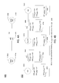
- FIGS. 5A-D illustrate further example CRPs and PRPs capable of being determined by the example OCDE 140 of FIGS. 1-3 for different example network topologies.
- FIG. 5A illustrates a first example network topology 500 including six (6) example nodes N 1 through N 6 interconnected by six (6) example links L 1 through L 6 , as shown.
- traffic for a service is to be routed between endpoint node N 1 and endpoint node N 6 .
- the example graph database 125 identifies two possible paths, P 1 and P 2 , capable of routing traffic between the pair of endpoint nodes N 1 and N 6 . As shown in the example of FIG.
- the path P 1 includes nodes N 1 , N 2 , N 3 and N 6 , which are interconnected by links L 1 , L 2 and L 3 , as shown.
- the path P 2 includes nodes N 1 , N 4 , N 5 and N 6 , which are interconnected by links L 4 , L 5 and L 6 , as shown.
- FIG. 5B illustrates example CRP parameters determined by the example OCDE 140 for the network components in the example topology 500 , and example PRP parameters determined by the example OCDE 140 for the possible paths P 1 and P 2 .
- the CRP parameters for the network nodes N 1 through N 6 are assumed to have negligible effect on the PRP parameters determined for the possible paths P 1 and P 2 . Accordingly, the CRP parameters for the network nodes N 1 through N 6 are omitted in FIG. 5B for clarity.
- the OCDE 140 determines, as disclosed above, a CRP of 1780 for link L 1 , a CRP of 1400 for link L 2 , a CRP of 600 for L 3 , a CRP of 1100 for link L 4 , a CRP of 3400 for link L 5 and a CRP of 2700 for link L 6 .
- FIG. 5C illustrates a second example network topology 505 in which an example node N 7 and example links L 7 and L 8 are added to the example network topology 500 as shown in the figure.
- the OCDE 140 determines, for the service to be routed between endpoint nodes N 1 and N 6 , a CRP of 3600 for link L 7 and a CRP of 3900 for link L 8 (the CRP for the node N 7 is assumed to be negligible and, thus, is omitted for clarity).
- the example graph database 125 returns path P 3 as another possible path for routing traffic between the endpoint nodes N 1 and N 6 .
- Path P 3 includes nodes N 1 , N 4 , N 7 and N 6 , which are interconnected by links L 4 , L 7 and L 8 , as shown.
- FIG. 5D illustrates a third example network topology 505 in which an example link L 9 is added to the example network topology 500 to interconnect example nodes N 2 and N 5 as shown in the figure.
- the OCDE 140 determines, for the service to be routed between endpoint nodes N 1 and N 6 , a CRP of 2900 for link L 9 .
- the example graph database 125 returns path P 4 as another possible path for routing traffic between the endpoint nodes N 1 and N 6 .
- Path P 4 includes nodes N 1 , N 2 , N 5 and N 6 , which are interconnected by links L 1 , L 9 and L 6 , as shown.
- FIG. 6 illustrates an example communication network 600 including a second example implementation of the configuration selector 105 of FIG. 1 .
- the example communication network 600 of FIG. 6 includes many elements in common with the example communication network 100 of FIG. 1 . As such, like elements in FIGS. 1 and 6 are labeled with the same reference numerals. The detailed descriptions of these like elements are provided above in connection with the discussion of FIG. 1 and, in the interest of brevity, are not repeated in the discussion of FIG. 6 .
- the configuration selector 105 includes an example OCDE 640 structured to support parallel processing. More specifically, the example OCDE 640 employs different processors and/or different processing threads to, for example, determine the sets of CRP parameters for the network components 110 , the respective PRP parameters for different candidate paths for routing different services in the network 600 , and the respective service-specific NSRP parameters in parallel with determining the sets of NRP parameters for different proposed network configurations. In this way, the OCDE 640 can continuously update (e.g., in real-time) the topology information in the network 600 as, for example, network components 110 are added/removed, and/or the performance measurements for network components 110 change.
- the example OCDE 640 employs different processors and/or different processing threads to, for example, determine the sets of CRP parameters for the network components 110 , the respective PRP parameters for different candidate paths for routing different services in the network 600 , and the respective service-specific NSRP parameters in parallel with determining the sets of NRP parameters for different proposed network configurations
- the OCDE 640 of FIG. 6 includes at least four example processors 645 , 650 , 655 , and 660 (or at least four example processing threads 645 , 650 , 655 , and 660 ) which operate in parallel.
- the processor 645 implements the example CRP determiner 210 and the example relative performance mapper 215 to determine sets of CRP parameters for the network components 110 .
- the example processor 650 implements the example path identifier 220 and the example PRP determiner 225 to determine service-specific PRP parameters for candidate paths identified in the network 600 .
- the example processor 655 implements the example NSRP determiner 250 to determine NSRP parameters for each service supported by the network 600 .
- the example processor 660 implements the example configuration identifier 230 , the example NRP determiner 255 , and the example configuration evaluator 260 to determine NRP parameters for proposed configurations of the network 600 and to select, based on the NRP parameters, a configuration (e.g., current or proposed) for the network 600 .
- the OCDE 640 includes further processors (and/or processing threads) to allow multiple instances of, for example, the example CRP determiner 210 to be executed to determine CRP parameters for different services in parallel.
- the OCDE 640 includes further processors (and/or processing threads) to allow multiple instances of, for example, the example PRP determiner 225 to be executed to determine PRP parameters for different candidate paths in parallel. Additionally or alternatively, in some examples, the OCDE 640 includes further processors (and/or processing threads) to allow multiple instances of, for example, the example NSRP determiner 250 to be executed to determine NSRP parameters for different services in parallel. Additionally or alternatively, in some examples, the OCDE 640 includes further processors (and/or processing threads) to allow multiple instances of, for example, the example NRP determiner 255 to be executed to determine NRP parameters for different network configurations in parallel.
- the example processor 645 , 650 , 655 , and/or 660 may be implemented by any number(s), type(s) and/or combination(s) of processors, such as the example processor 802 of FIG. 8 , which is described in further detail below.
- FIGS. 1-6 While example manners of implementing the example configuration selector 105 is illustrated in FIGS. 1-6 , one or more of the elements, processes and/or devices illustrated in FIGS. 1-6 may be combined, divided, re-arranged, omitted, eliminated and/or implemented in any other way.
- At least one of the example configuration selector 105 , the example network components 110 , the example graph database 125 , the example network controller(s) 130 , the example network monitor(s) 135 , the example OCDEs 140 and/or 640 , the example policy storage 145 , the example graph database interface 205 , the example CRP determiner 210 , the example relative performance mapper 215 , the example path identifier 220 , the example PRP determiner 225 , the example ZNSRP determiner 250 , the example configuration identifier 230 , the example NRP determiner 255 , the example configuration evaluator 260 , the example processors 645 , 650 , 655 , and/or 660 is/are hereby expressly defined to include a tangible computer readable storage device or storage disk such as a memory, a digital versatile disk (DVD), a compact disk (CD), a Blu-ray
- example configuration selector 105 may include one or more elements, processes and/or devices in addition to, or instead of, those illustrated in FIGS. 1-6 , and/or may include more than one of any or all of the illustrated elements, processes and devices.
- machine readable instructions may implement the example configuration selector 105 , the example network components 110 , the example graph database 125 , the example network controller(s) 130 , the example network monitor(s) 135 , the example OCDEs 140 and/or 640 , the example policy storage 145 , the example graph database interface 205 , the example CRP determiner 210 , the example relative performance mapper 215 , the example path identifier 220 , the example PRP determiner 225 , the example ZNSRP determiner 250 , the example configuration identifier 230 , the example NRP determiner 255 , the example configuration evaluator 260 , the example processors 645 , 650 , 655 , and/or 660 .
- the machine readable instructions comprise one or more programs for execution by a processor, such as the processor 802 shown in the example processor platform 800 discussed below in connection with FIG. 8 .
- the one or more programs, or portion(s) thereof may be embodied in software stored on a tangible computer readable storage medium such as a CD-ROM, a floppy disk, a hard drive, a digital versatile disk (DVD), a Blu-ray DiskTM, or a memory associated with the processor 802 , but the entire program or programs and/or portions thereof could alternatively be executed by a device other than the processor 802 and/or embodied in firmware or dedicated hardware (e.g., implemented by an ASIC, a PLD, an FPLD, discrete logic, etc.).
- firmware or dedicated hardware e.g., implemented by an ASIC, a PLD, an FPLD, discrete logic, etc.
- the example configuration selector 105 , the example network components 110 , the example graph database 125 , the example network controller(s) 130 , the example network monitor(s) 135 , the example OCDEs 140 and/or 640 , the example policy storage 145 , the example graph database interface 205 , the example CRP determiner 210 , the example relative performance mapper 215 , the example path identifier 220 , the example PRP determiner 225 , the example ZNSRP determiner 250 , the example configuration identifier 230 , the example NRP determiner 255 , the example configuration evaluator 260 , the example processors 645 , 650 , 655 , and/or 660 may be implemented using coded instructions (e.g., computer and/or machine readable instructions) stored on a tangible computer readable storage medium such as a hard disk drive, a flash memory, a read-only memory (ROM), a compact disk (CD), a digital versatile disk (DVD), a cache
- tangible computer readable storage medium is expressly defined to include any type of computer readable storage device and/or storage disk and to exclude propagating signals and to exclude transmission media.
- tangible computer readable storage medium and “tangible machine readable storage medium” are used interchangeably.
- the example configuration selector 105 , the example network components 110 , the example graph database 125 , the example network controller(s) 130 , the example network monitor(s) 135 , the example OCDEs 140 and/or 640 , the example policy storage 145 , the example graph database interface 205 , the example CRP determiner 210 , the example relative performance mapper 215 , the example path identifier 220 , the example PRP determiner 225 , the example ZNSRP determiner 250 , the example configuration identifier 230 , the example NRP determiner 255 , the example configuration evaluator 260 , the example processors 645 , 650 , 655 , and/or 660 may be implemented using coded instructions (e.g., computer and/or machine readable instructions) stored on a non-transitory computer and/or machine readable medium such as a hard disk drive, a flash memory, a ROM, a CD, a DVD, a cache, a RAM
- non-transitory computer readable medium is expressly defined to include any type of computer readable storage device and/or storage disk and to exclude propagating signals and to exclude transmission media.
- phrase “at least” is used as the transition term in a preamble of a claim, it is open-ended in the same manner as the terms “comprising” and “including” are open ended.
- computer readable and “machine readable” are considered equivalent unless indicated otherwise.
- FIG. 7 is a flowchart illustrating an example program 700 that may be executed to implement the example configuration selector 105 of FIGS. 1-6 .
- the example program 700 of FIG. 7 begins execution at block 705 and proceeds to block 710 , at which the example OCDE 140 of the configuration selector 105 identifies a proposed network configuration.
- the proposed network configuration is identified using the configuration identifier 230 of the example OCDE 140 and represents an incremental change to the current network configuration.
- the example OCDE 140 models, e.g., via the configuration identifier 230 , the proposed network configuration in real time, for instance using a virtual network model.
- the example OCDE 140 queries the example graph database 125 of the configuration selector 105 to access respective sets of performance measurements for the network components 110 included in the network 100 under the proposed configuration.
- the OCDE 140 maps the sets of performance measurements accessed at block 705 to corresponding sets of mapped performance parameters, as described above.
- the OCDE 140 determines (e.g., according to Equation 1, as described above) respective sets of service specific CRP parameters for the network components 110 based on the sets of mapped performance parameters determined at block 725 and the service specific policies accessed from the example policy storage 145 of the configuration selector 105 .
- the OCDE 140 queries the graph database 125 to identify one or more sets of candidate paths capable of routing traffic for one or more services between one or more pairs of endpoints in the network 100 .
- the OCDE 140 determines (e.g., according to Equation 2, as described above) respective service specific PRP parameters for the identified candidate paths based on the service specific CRP parameters determined at block 730 for the network components 110 .
- the OCDE 140 determines (e.g., according to Equation 3, as described above) network service relative performance parameters for the services supported by the network, based on the service specific PRP parameters determined at block 740 .
- the OCDE 140 determines (e.g., according to Equation 4, as described above) network relative performance parameters for the proposed network configuration, based on the service specific NSRP parameters determined at block 745 .
- the example OCDE 140 selects, based on the NRP parameters determined at block 750 , the optimal configuration for the network 100 .
- the optimal configuration is whichever of the current configuration and the proposed configuration has the higher-value NRP parameters.
- the OCDE 140 transmits configuration information describing the selected configuration to, for example, the network controller(s) 130 to enable the network components 110 to be arranged according to the selected network configuration.
- the method 700 then ends in block 765 .
- the example program 700 is depicted as being executed sequentially. However, execution of the example program 700 is not limited thereto.
- the program 700 supports parallel execution by two or more parallel processing threads.
- the processing at one or more of blocks 705 - 730 may be performed by a first example processing thread 770
- the processing at one or more of blocks 735 - 765 may be performed by a second example processing thread 775 executing in parallel with the first processing thread 770 .
- Such an example implementation permits processing related to determining the sets of service specific CRP parameters for the network components 110 and processing related to determining the service specific PRP parameters for the candidate paths to be performed in parallel.
- Other parallel processing arrangements such as those described above in connection with FIG. 6 , are supported by the example program 700 of FIG. 7 . For instance, additional separate processing threads could be established to support determination of the NSRP and/or NRP parameters in parallel with the CRP and PRP parameters.
- FIG. 8 is a block diagram of an example processor platform 800 capable of executing the instructions of FIG. 6 to implement the example configuration selector 105 of FIGS. 1-6 .
- the processor platform 800 can be, for example, a server, a personal computer, a mobile device (e.g., a cell phone, a smart phone, a tablet computer), a personal digital assistant (PDA), an Internet appliance, or any other type of computing device.
- a server e.g., a server, a personal computer, a mobile device (e.g., a cell phone, a smart phone, a tablet computer), a personal digital assistant (PDA), an Internet appliance, or any other type of computing device.
- PDA personal digital assistant
- the processor platform 800 of the illustrated example includes a processor 802 .
- the processor 802 of the illustrated example is hardware.
- the processor 802 can be implemented by one or more integrated circuits, logic circuits, microprocessors or controllers from any desired family or manufacturer.
- the processor 802 includes one or more example processing cores 806 configured via example instructions 826 , which include the example instructions of FIG. 6 to implement the example CRP determiner 210 , the example relative performance mapper 215 , the example path identifier 220 , the example PRP determiner 225 , the example NSRP determiner 250 , the example configuration identifier 230 , the example NRP determiner 255 , or the example configuration evaluator 260 of FIG. 2 .
- the processor 802 of the illustrated example includes a local memory 804 (e.g., a cache).
- the processor 802 of the illustrated example is in communication with a main memory including a volatile memory 808 and a non-volatile memory 810 via a link 820 .
- the link 820 may be implemented by a bus, one or more point-to-point connections, etc., or a combination thereof.
- the volatile memory 808 may be implemented by Synchronous Dynamic Random Access Memory (SDRAM), Dynamic Random Access Memory (DRAM), RAMBUS Dynamic Random Access Memory (RDRAM) and/or any other type of random access memory device.
- the non-volatile memory 810 may be implemented by flash memory and/or any other desired type of memory device. Access to the main memory 808 , 810 is controlled by a memory controller.
- the processor platform 800 of the illustrated example also includes an interface circuit 816 .
- the interface circuit 816 may be implemented by any type of interface standard, such as an Ethernet interface, a universal serial bus (USB), and/or a PCI express interface.
- one or more input devices 814 are connected to the interface circuit 816 .
- the input device(s) 814 permit(s) a user to enter data and commands into the processor 802 .
- the input device(s) can be implemented by, for example, an audio sensor, a microphone, a camera (still or video), a keyboard, a button, a mouse, a touchscreen, a track-pad, a trackball, a trackbar (such as an isopoint), a voice recognition system and/or any other human-machine interface.
- many systems, such as the processor platform 800 can allow the user to control the computer system and provide data to the computer using physical gestures, such as, but not limited to, hand or body movements, facial expressions, and face recognition.
- One or more output devices 818 are also connected to the interface circuit 816 of the illustrated example.
- the output devices 818 can be implemented, for example, by display devices (e.g., a light emitting diode (LED), an organic light emitting diode (OLED), a liquid crystal display, a cathode ray tube display (CRT), a touchscreen, a tactile output device, a printer and/or speakers).
- the interface circuit 820 of the illustrated example thus, typically includes a graphics driver card, a graphics driver chip or a graphics driver processor.
- the interface circuit 816 of the illustrated example also includes a communication device such as a transmitter, a receiver, a transceiver, a modem and/or network interface card to facilitate exchange of data with external machines (e.g., computing devices of any kind) via a network 820 (e.g., an Ethernet connection, a digital subscriber line (DSL), a telephone line, coaxial cable, a cellular telephone system, etc.).
- a network 820 e.g., an Ethernet connection, a digital subscriber line (DSL), a telephone line, coaxial cable, a cellular telephone system, etc.
- the interface circuit 816 is also structured to implement the example graph database interface 205 .
- the processor platform 800 of the illustrated example also includes one or more mass storage devices 812 for storing software and/or data.
- mass storage devices 812 include floppy disk drives, hard drive disks, compact disk drives, Blu-ray disk drives, RAID (redundant array of independent disks) systems, and digital versatile disk (DVD) drives.
- the mass storage device 812 may implement the example graph database 125 and/or the example policy storage 145 .
- the volatile memory 808 may implement the example graph database 125 and/or the example service profile storage 145 .
- Coded instructions 826 corresponding to the instructions of FIG. 6 may be stored in the mass storage device 812 , in the volatile memory 808 , in the non-volatile memory 810 , in the local memory 804 and/or on a removable tangible computer readable storage medium, such as a CD or DVD 822 .
- At least some of the above described example methods and/or apparatus are implemented by one or more software and/or firmware programs running on a computer processor.
- dedicated hardware implementations including, but not limited to, application specific integrated circuits, programmable logic arrays and other hardware devices can likewise be constructed to implement some or all of the example methods and/or apparatus described herein, either in whole or in part.
- alternative software implementations including, but not limited to, distributed processing or component/object distributed processing, parallel processing, or virtual machine processing can also be constructed to implement the example methods and/or apparatus described herein.
Abstract
Description
| TABLE 1 | ||||||
| Bearer | Pri- | Packet | Packet | |||
| QCI | Type | ority | Delay | Loss | Example | |
| 1 | |
2 | 100 ms | 10−2 | |
|
| 2 | 4 | 150 ms | 10−3 | |
||
| 3 | 3 | 50 ms | Online Gaming (Real Time) | |||
| 4 | 5 | 300 ms | 10−6 | Video streaming | ||
| 5 | |
1 | 100 | IMS Signaling | ||
| 6 | 6 | 300 ms | Video, TCP based services | |||
| e.g. email, chat, ftp etc | ||||||
| 7 | 7 | 100 ms | 10−3 | Voice, Video, Interactive | ||
| gaming | ||||||
| 8 | 8 | 300 ms | 10−6 | Video, TCP based services | ||
| 9 | 9 | e.g. email, chat, ftp etc | ||||
In
In
In
PRPP1=1780+1400+600=3780
Similarly, the
PRPP2=1100+3400+2700=7200
PRPP3=1100+3600+3900=7600 Equation 7
PRPP4=1780+2900+2700=7380 Equation 8
Claims (20)
Priority Applications (3)
| Application Number | Priority Date | Filing Date | Title |
|---|---|---|---|
| US14/986,294 US10439867B2 (en) | 2015-12-31 | 2015-12-31 | Method and apparatus for optimizing a software defined network configuration |
| US16/592,904 US11082290B2 (en) | 2015-12-31 | 2019-10-04 | Method and apparatus for optimizing a software defined network configuration |
| US17/392,249 US20210367835A1 (en) | 2015-12-31 | 2021-08-02 | Method and apparatus for optimizing a software defined network configuration |
Applications Claiming Priority (1)
| Application Number | Priority Date | Filing Date | Title |
|---|---|---|---|
| US14/986,294 US10439867B2 (en) | 2015-12-31 | 2015-12-31 | Method and apparatus for optimizing a software defined network configuration |
Related Child Applications (1)
| Application Number | Title | Priority Date | Filing Date |
|---|---|---|---|
| US16/592,904 Continuation US11082290B2 (en) | 2015-12-31 | 2019-10-04 | Method and apparatus for optimizing a software defined network configuration |
Publications (2)
| Publication Number | Publication Date |
|---|---|
| US20170195171A1 US20170195171A1 (en) | 2017-07-06 |
| US10439867B2 true US10439867B2 (en) | 2019-10-08 |
Family
ID=59227290
Family Applications (3)
| Application Number | Title | Priority Date | Filing Date |
|---|---|---|---|
| US14/986,294 Expired - Fee Related US10439867B2 (en) | 2015-12-31 | 2015-12-31 | Method and apparatus for optimizing a software defined network configuration |
| US16/592,904 Active 2036-01-19 US11082290B2 (en) | 2015-12-31 | 2019-10-04 | Method and apparatus for optimizing a software defined network configuration |
| US17/392,249 Abandoned US20210367835A1 (en) | 2015-12-31 | 2021-08-02 | Method and apparatus for optimizing a software defined network configuration |
Family Applications After (2)
| Application Number | Title | Priority Date | Filing Date |
|---|---|---|---|
| US16/592,904 Active 2036-01-19 US11082290B2 (en) | 2015-12-31 | 2019-10-04 | Method and apparatus for optimizing a software defined network configuration |
| US17/392,249 Abandoned US20210367835A1 (en) | 2015-12-31 | 2021-08-02 | Method and apparatus for optimizing a software defined network configuration |
Country Status (1)
| Country | Link |
|---|---|
| US (3) | US10439867B2 (en) |
Cited By (2)
| Publication number | Priority date | Publication date | Assignee | Title |
|---|---|---|---|---|
| US20200119987A1 (en) * | 2018-10-15 | 2020-04-16 | Red Hat, Inc. | Software defined network optimization using quantum computing |
| US20240031224A1 (en) * | 2022-07-20 | 2024-01-25 | At&T Intellectual Property I, L.P. | Network optimization for hybrid quantum-classical networks |
Families Citing this family (12)
| Publication number | Priority date | Publication date | Assignee | Title |
|---|---|---|---|---|
| US10516761B1 (en) * | 2017-03-17 | 2019-12-24 | Juniper Networks, Inc. | Configuring and managing network devices using program overlay on Yang-based graph database |
| US10666508B2 (en) * | 2017-06-09 | 2020-05-26 | Nicira, Inc. | Unified software defined networking configuration management over multiple hosting environments |
| US20190199595A1 (en) * | 2017-12-22 | 2019-06-27 | Avaya Inc. | Attribute and property overrides for remote network topology changes |
| US11405281B2 (en) | 2018-03-25 | 2022-08-02 | British Telecommunications Public Limited Company | Dynamic network adaptation |
| GB2572329B8 (en) * | 2018-03-25 | 2021-03-10 | British Telecomm | Dynamic network adaptation |
| US11296939B2 (en) * | 2018-07-17 | 2022-04-05 | At&T Intellectual Property I, L.P. | Network reconfiguration with customer premises-based application hosting |
| US11265292B1 (en) * | 2019-01-28 | 2022-03-01 | Amazon Technologies, Inc. | Graph based management of virtualized infrastructures |
| US11546224B2 (en) * | 2019-05-09 | 2023-01-03 | Red Hat, Inc. | Virtual network layer for distributed systems |
| US11108617B2 (en) * | 2019-06-14 | 2021-08-31 | At&T Intellectual Property I, L.P. | Methods, systems, and devices for provisioning an application on a network node according to movement patterns and application parameters for mobile devices |
| US10979309B2 (en) * | 2019-08-07 | 2021-04-13 | Schweitzer Engineering Laboratories, Inc. | Automated convergence of physical design and configuration of software defined network |
| US11303517B2 (en) | 2020-01-07 | 2022-04-12 | International Business Machines Corporation | Software patch optimization |
| US11496610B2 (en) * | 2020-06-26 | 2022-11-08 | Verizon Patent And Licensing Inc. | Network management data translation, querying, and discrepancy detection |
Citations (31)
| Publication number | Priority date | Publication date | Assignee | Title |
|---|---|---|---|---|
| US5042027A (en) | 1988-09-12 | 1991-08-20 | Hitachi, Ltd. | Communication network system and method of controlling a communication network |
| US20030087645A1 (en) | 2001-11-08 | 2003-05-08 | Kim Byoung-Jo J. | Frequency assignment for multi-cell IEEE 802.11 wireless networks |
| US7158759B2 (en) | 2001-04-13 | 2007-01-02 | Broadcom Corporation | Dynamic frequency selection in a wireless communication network |
| US7251491B2 (en) | 2003-07-31 | 2007-07-31 | Qualcomm Incorporated | System of and method for using position, velocity, or direction of motion estimates to support handover decisions |
| US20080114874A1 (en) * | 2006-11-15 | 2008-05-15 | Cisco Technology, Inc. | Root cause analysis in a communication network |
| US20090046583A1 (en) * | 2007-08-13 | 2009-02-19 | Henry Towster | Methods and apparatus to control traffic in a packet-switched network |
| US7564925B2 (en) | 2004-12-23 | 2009-07-21 | Alcatel | Analog-to-digital converter with a decision circuit and an optimized decision threshold |
| US20110199899A1 (en) | 2010-02-16 | 2011-08-18 | Lime Brokerage Holding Llc | Rate-Adaptive Bundling of Data in a Packetized Communication System |
| US20120176928A1 (en) | 2002-10-25 | 2012-07-12 | Qualcomm Incorporated | Channel calibration for a time division duplexed communication system |
| US20120266159A1 (en) * | 2011-03-16 | 2012-10-18 | Pankaj Risbood | Selection of Ranked Configurations |
| US20120275309A1 (en) * | 2011-04-29 | 2012-11-01 | Verizon Patent And Licensing Inc. | Routing cost normalizing |
| US8582584B2 (en) | 2005-10-04 | 2013-11-12 | Time Warner Cable Enterprises Llc | Self-monitoring and optimizing network apparatus and methods |
| WO2014035807A1 (en) | 2012-08-29 | 2014-03-06 | Nec Laboratories America, Inc. | Data processing |
| US20140136690A1 (en) * | 2012-11-15 | 2014-05-15 | Microsoft Corporation | Evaluating Electronic Network Devices In View of Cost and Service Level Considerations |
| US20140164045A1 (en) * | 2012-12-12 | 2014-06-12 | International Business Machines Corporation | System and method for determining optimal asset configurations while minimizing disruption to existing business operations in a service delivery environment |
| EP2753032A1 (en) | 2013-01-04 | 2014-07-09 | Tellabs Oy | A method and a controller system for configuring a software-defined network |
| US20140280961A1 (en) * | 2013-03-15 | 2014-09-18 | Frank Martinez | System and method for a cloud computing abstraction with multi-tier deployment policy |
| US20140328190A1 (en) | 2013-04-25 | 2014-11-06 | Accelera Mobile Broadband, Inc. | Cloud-based management platform for heterogeneous wireless devices |
| US8891664B2 (en) | 2010-03-31 | 2014-11-18 | Kabushiki Kaisha Toshiba | Transmitter and receiver |
| US8908556B2 (en) | 2008-08-20 | 2014-12-09 | Qualcomm Incorporated | Method and apparatus to perform ranging operations for wireless stations |
| US20150063144A1 (en) | 2013-09-04 | 2015-03-05 | Ulas C. Kozat | Method and apparatus for software defined flow control in wireless systems |
| US8976697B2 (en) | 2012-12-17 | 2015-03-10 | Broadcom Corporation | Network status mapping |
| WO2015103523A1 (en) | 2014-01-06 | 2015-07-09 | Cisco Technology, Inc. | Predictive learning machine-based approach to detect traffic outside of service level agreements |
| US9113352B2 (en) | 2012-09-25 | 2015-08-18 | Parallel Wireless, Inc. | Heterogeneous self-organizing network for access and backhaul |
| US9124506B2 (en) | 2013-06-07 | 2015-09-01 | Brocade Communications Systems, Inc. | Techniques for end-to-end network bandwidth optimization using software defined networking |
| US20150281085A1 (en) | 2014-01-23 | 2015-10-01 | InMon Corp. | Method and system of large flow control in communication networks |
| US20150333862A1 (en) | 2014-05-19 | 2015-11-19 | Ciena Corporation | Margin-based optimization systems and methods in optical networks by intentionally reducing margin |
| US20160057061A1 (en) * | 2014-08-22 | 2016-02-25 | Futurewei Technologies, Inc. | Learning Or Emulation Approach to Traffic Engineering in Information-Centric Networks |
| US9325585B1 (en) * | 2012-07-10 | 2016-04-26 | The Boeing Company | Mission-driven autonomous and adaptive resource management |
| US20160182329A1 (en) * | 2014-12-19 | 2016-06-23 | Ciena Corporation | Bandwidth optimization systems and methods in networks |
| US20160212634A1 (en) * | 2015-01-19 | 2016-07-21 | Jdsu Uk Limited | Techniques for dynamic network optimization using geolocation and network modeling |
Family Cites Families (2)
| Publication number | Priority date | Publication date | Assignee | Title |
|---|---|---|---|---|
| US10148578B2 (en) * | 2014-10-17 | 2018-12-04 | Ciena Corporation | Optical and packet path computation and selection systems and methods |
| US9819565B2 (en) * | 2015-01-26 | 2017-11-14 | Ciena Corporation | Dynamic policy engine for multi-layer network management |
-
2015
- 2015-12-31 US US14/986,294 patent/US10439867B2/en not_active Expired - Fee Related
-
2019
- 2019-10-04 US US16/592,904 patent/US11082290B2/en active Active
-
2021
- 2021-08-02 US US17/392,249 patent/US20210367835A1/en not_active Abandoned
Patent Citations (31)
| Publication number | Priority date | Publication date | Assignee | Title |
|---|---|---|---|---|
| US5042027A (en) | 1988-09-12 | 1991-08-20 | Hitachi, Ltd. | Communication network system and method of controlling a communication network |
| US7158759B2 (en) | 2001-04-13 | 2007-01-02 | Broadcom Corporation | Dynamic frequency selection in a wireless communication network |
| US20030087645A1 (en) | 2001-11-08 | 2003-05-08 | Kim Byoung-Jo J. | Frequency assignment for multi-cell IEEE 802.11 wireless networks |
| US20120176928A1 (en) | 2002-10-25 | 2012-07-12 | Qualcomm Incorporated | Channel calibration for a time division duplexed communication system |
| US7251491B2 (en) | 2003-07-31 | 2007-07-31 | Qualcomm Incorporated | System of and method for using position, velocity, or direction of motion estimates to support handover decisions |
| US7564925B2 (en) | 2004-12-23 | 2009-07-21 | Alcatel | Analog-to-digital converter with a decision circuit and an optimized decision threshold |
| US8582584B2 (en) | 2005-10-04 | 2013-11-12 | Time Warner Cable Enterprises Llc | Self-monitoring and optimizing network apparatus and methods |
| US20080114874A1 (en) * | 2006-11-15 | 2008-05-15 | Cisco Technology, Inc. | Root cause analysis in a communication network |
| US20090046583A1 (en) * | 2007-08-13 | 2009-02-19 | Henry Towster | Methods and apparatus to control traffic in a packet-switched network |
| US8908556B2 (en) | 2008-08-20 | 2014-12-09 | Qualcomm Incorporated | Method and apparatus to perform ranging operations for wireless stations |
| US20110199899A1 (en) | 2010-02-16 | 2011-08-18 | Lime Brokerage Holding Llc | Rate-Adaptive Bundling of Data in a Packetized Communication System |
| US8891664B2 (en) | 2010-03-31 | 2014-11-18 | Kabushiki Kaisha Toshiba | Transmitter and receiver |
| US20120266159A1 (en) * | 2011-03-16 | 2012-10-18 | Pankaj Risbood | Selection of Ranked Configurations |
| US20120275309A1 (en) * | 2011-04-29 | 2012-11-01 | Verizon Patent And Licensing Inc. | Routing cost normalizing |
| US9325585B1 (en) * | 2012-07-10 | 2016-04-26 | The Boeing Company | Mission-driven autonomous and adaptive resource management |
| WO2014035807A1 (en) | 2012-08-29 | 2014-03-06 | Nec Laboratories America, Inc. | Data processing |
| US9113352B2 (en) | 2012-09-25 | 2015-08-18 | Parallel Wireless, Inc. | Heterogeneous self-organizing network for access and backhaul |
| US20140136690A1 (en) * | 2012-11-15 | 2014-05-15 | Microsoft Corporation | Evaluating Electronic Network Devices In View of Cost and Service Level Considerations |
| US20140164045A1 (en) * | 2012-12-12 | 2014-06-12 | International Business Machines Corporation | System and method for determining optimal asset configurations while minimizing disruption to existing business operations in a service delivery environment |
| US8976697B2 (en) | 2012-12-17 | 2015-03-10 | Broadcom Corporation | Network status mapping |
| EP2753032A1 (en) | 2013-01-04 | 2014-07-09 | Tellabs Oy | A method and a controller system for configuring a software-defined network |
| US20140280961A1 (en) * | 2013-03-15 | 2014-09-18 | Frank Martinez | System and method for a cloud computing abstraction with multi-tier deployment policy |
| US20140328190A1 (en) | 2013-04-25 | 2014-11-06 | Accelera Mobile Broadband, Inc. | Cloud-based management platform for heterogeneous wireless devices |
| US9124506B2 (en) | 2013-06-07 | 2015-09-01 | Brocade Communications Systems, Inc. | Techniques for end-to-end network bandwidth optimization using software defined networking |
| US20150063144A1 (en) | 2013-09-04 | 2015-03-05 | Ulas C. Kozat | Method and apparatus for software defined flow control in wireless systems |
| WO2015103523A1 (en) | 2014-01-06 | 2015-07-09 | Cisco Technology, Inc. | Predictive learning machine-based approach to detect traffic outside of service level agreements |
| US20150281085A1 (en) | 2014-01-23 | 2015-10-01 | InMon Corp. | Method and system of large flow control in communication networks |
| US20150333862A1 (en) | 2014-05-19 | 2015-11-19 | Ciena Corporation | Margin-based optimization systems and methods in optical networks by intentionally reducing margin |
| US20160057061A1 (en) * | 2014-08-22 | 2016-02-25 | Futurewei Technologies, Inc. | Learning Or Emulation Approach to Traffic Engineering in Information-Centric Networks |
| US20160182329A1 (en) * | 2014-12-19 | 2016-06-23 | Ciena Corporation | Bandwidth optimization systems and methods in networks |
| US20160212634A1 (en) * | 2015-01-19 | 2016-07-21 | Jdsu Uk Limited | Techniques for dynamic network optimization using geolocation and network modeling |
Non-Patent Citations (4)
| Title |
|---|
| "Software-Defined Networking: The New Norm for Networks," Open Network Foundation, bigswitch.com, Apr. 13, 2012. http://bigswitch.com/sites/default/files/sdn_resources/onf-whitepaper.pdf Discloses a software defined network which can configure, manage, secure, and optimize network resources via dynamic, automated programs. |
| Kim, Hyojoon, and Nick Feamster, "Improving Network Management with Software Defined Networking," IEEE Communications Magazine, sharecourse.com, 2013. http://www.comsoc.org/sites/default/files/webfm/Publications/Magazines/ci/ofc/014.pdf Discloses a software defined network which can perform automated functions based on control domains including network flow and status. |
| Moshref, Masoud, et al., "DREAM: dynamic resource allocation for software-defined measurement," Proceedings of the 2014 ACM conference on SIGCOMM, ACM, 2014. http://sysnet.ucsd.edu/sysnet/miscpapers/DreamSigcomm14.pdf Discloses a software defined network which dynamically adjusts network resources. |
| Slattery, Terry, "Software-Defined Network Management: What we Need," No Jitter, nojitter.com, Nov. 5, 2015. http://www.nojitter.com/post/240170874/softwaredefined-network-management-what-we-need Discloses a software defined network which automatically monitors key network metrics. |
Cited By (3)
| Publication number | Priority date | Publication date | Assignee | Title |
|---|---|---|---|---|
| US20200119987A1 (en) * | 2018-10-15 | 2020-04-16 | Red Hat, Inc. | Software defined network optimization using quantum computing |
| US11245584B2 (en) * | 2018-10-15 | 2022-02-08 | Red Hat, Inc. | Software defined network optimization using quantum computing |
| US20240031224A1 (en) * | 2022-07-20 | 2024-01-25 | At&T Intellectual Property I, L.P. | Network optimization for hybrid quantum-classical networks |
Also Published As
| Publication number | Publication date |
|---|---|
| US11082290B2 (en) | 2021-08-03 |
| US20210367835A1 (en) | 2021-11-25 |
| US20200106665A1 (en) | 2020-04-02 |
| US20170195171A1 (en) | 2017-07-06 |
Similar Documents
| Publication | Publication Date | Title |
|---|---|---|
| US11082290B2 (en) | Method and apparatus for optimizing a software defined network configuration | |
| US10735314B2 (en) | Service specific route selection in communication networks | |
| US10548032B2 (en) | Network anomaly detection and network performance status determination | |
| US11153196B2 (en) | Efficient machine learning for network optimization | |
| CN108900419B (en) | Routing decision method and device based on deep reinforcement learning under SDN framework | |
| EP3047609B1 (en) | Systems and method for reconfiguration of routes | |
| Claeys et al. | Design and optimisation of a (FA) Q-learning-based HTTP adaptive streaming client | |
| US10833934B2 (en) | Energy management in a network | |
| CN113408139B (en) | Power communication network path control simulation verification method, device, equipment and medium | |
| CN110311863B (en) | Routing path determination method and device | |
| WO2016018859A1 (en) | Propagating routing awareness for autonomous networks | |
| CN114189434A (en) | Intelligent data traffic routing in wide area networks | |
| Chen et al. | Deterministic quality of service guarantee for dynamic service chaining in software defined networking | |
| Cai et al. | SARM: service function chain active reconfiguration mechanism based on load and demand prediction | |
| CN108476175A (en) | Use the transmission SDN traffic engineering method and systems of dual variable | |
| CN104022951A (en) | Building method and system for network service path | |
| WO2022101378A1 (en) | Method and system for predicting a network characteristic | |
| CN111901237B (en) | Source routing method and system, related device and computer readable storage medium | |
| US20180074570A1 (en) | Power aware switching using analytics | |
| CN105917621B (en) | Method and system for data routing | |
| Pinheiro et al. | A fuzzy queue-aware routing approach for wireless mesh networks | |
| Karimi et al. | Mining historical data towards interference management in wireless sdns | |
| Borges et al. | Performance assessment of cluster load balancing routing methods for triple play services in Wireless Mesh Networks | |
| JP6791532B2 (en) | Network traffic control system and control method | |
| Kabuatila | Analyze network performance computer science in optimizing packet routing |
Legal Events
| Date | Code | Title | Description |
|---|---|---|---|
| AS | Assignment |
Owner name: AT&T INTELLECTUAL PROPERTY I, L.P., GEORGIA Free format text: ASSIGNMENT OF ASSIGNORS INTEREST;ASSIGNORS:WOHLERT, RANDOLPH;AARON, JEFFREY A.;STOCKERT, MARK;SIGNING DATES FROM 20151228 TO 20160114;REEL/FRAME:037499/0265 |
|
| STPP | Information on status: patent application and granting procedure in general |
Free format text: FINAL REJECTION MAILED |
|
| STPP | Information on status: patent application and granting procedure in general |
Free format text: NOTICE OF ALLOWANCE MAILED -- APPLICATION RECEIVED IN OFFICE OF PUBLICATIONS |
|
| STPP | Information on status: patent application and granting procedure in general |
Free format text: PUBLICATIONS -- ISSUE FEE PAYMENT RECEIVED |
|
| STPP | Information on status: patent application and granting procedure in general |
Free format text: PUBLICATIONS -- ISSUE FEE PAYMENT VERIFIED |
|
| STCF | Information on status: patent grant |
Free format text: PATENTED CASE |
|
| FEPP | Fee payment procedure |
Free format text: MAINTENANCE FEE REMINDER MAILED (ORIGINAL EVENT CODE: REM.); ENTITY STATUS OF PATENT OWNER: LARGE ENTITY |
|
| LAPS | Lapse for failure to pay maintenance fees |
Free format text: PATENT EXPIRED FOR FAILURE TO PAY MAINTENANCE FEES (ORIGINAL EVENT CODE: EXP.); ENTITY STATUS OF PATENT OWNER: LARGE ENTITY |
|
| STCH | Information on status: patent discontinuation |
Free format text: PATENT EXPIRED DUE TO NONPAYMENT OF MAINTENANCE FEES UNDER 37 CFR 1.362 |
|
| FP | Lapsed due to failure to pay maintenance fee |
Effective date: 20231008 |