US10434601B2 - Welding process with an arc welder and beam welder for a weld turbulator - Google Patents
Welding process with an arc welder and beam welder for a weld turbulator Download PDFInfo
- Publication number
- US10434601B2 US10434601B2 US15/631,131 US201715631131A US10434601B2 US 10434601 B2 US10434601 B2 US 10434601B2 US 201715631131 A US201715631131 A US 201715631131A US 10434601 B2 US10434601 B2 US 10434601B2
- Authority
- US
- United States
- Prior art keywords
- weld
- turbulator
- welder
- fusion edge
- arc
- Prior art date
- Legal status (The legal status is an assumption and is not a legal conclusion. Google has not performed a legal analysis and makes no representation as to the accuracy of the status listed.)
- Active, expires
Links
Images


Classifications
-
- B—PERFORMING OPERATIONS; TRANSPORTING
- B23—MACHINE TOOLS; METAL-WORKING NOT OTHERWISE PROVIDED FOR
- B23K—SOLDERING OR UNSOLDERING; WELDING; CLADDING OR PLATING BY SOLDERING OR WELDING; CUTTING BY APPLYING HEAT LOCALLY, e.g. FLAME CUTTING; WORKING BY LASER BEAM
- B23K26/00—Working by laser beam, e.g. welding, cutting or boring
- B23K26/34—Laser welding for purposes other than joining
- B23K26/342—Build-up welding
-
- B—PERFORMING OPERATIONS; TRANSPORTING
- B23—MACHINE TOOLS; METAL-WORKING NOT OTHERWISE PROVIDED FOR
- B23K—SOLDERING OR UNSOLDERING; WELDING; CLADDING OR PLATING BY SOLDERING OR WELDING; CUTTING BY APPLYING HEAT LOCALLY, e.g. FLAME CUTTING; WORKING BY LASER BEAM
- B23K26/00—Working by laser beam, e.g. welding, cutting or boring
- B23K26/346—Working by laser beam, e.g. welding, cutting or boring in combination with welding or cutting covered by groups B23K5/00 - B23K25/00, e.g. in combination with resistance welding
- B23K26/348—Working by laser beam, e.g. welding, cutting or boring in combination with welding or cutting covered by groups B23K5/00 - B23K25/00, e.g. in combination with resistance welding in combination with arc heating, e.g. tungsten inert gas [TIG], metal inert gas [MIG] or plasma welding
-
- B—PERFORMING OPERATIONS; TRANSPORTING
- B23—MACHINE TOOLS; METAL-WORKING NOT OTHERWISE PROVIDED FOR
- B23K—SOLDERING OR UNSOLDERING; WELDING; CLADDING OR PLATING BY SOLDERING OR WELDING; CUTTING BY APPLYING HEAT LOCALLY, e.g. FLAME CUTTING; WORKING BY LASER BEAM
- B23K9/00—Arc welding or cutting
- B23K9/04—Welding for other purposes than joining, e.g. built-up welding
- B23K9/042—Built-up welding on planar surfaces
-
- B—PERFORMING OPERATIONS; TRANSPORTING
- B23—MACHINE TOOLS; METAL-WORKING NOT OTHERWISE PROVIDED FOR
- B23K—SOLDERING OR UNSOLDERING; WELDING; CLADDING OR PLATING BY SOLDERING OR WELDING; CUTTING BY APPLYING HEAT LOCALLY, e.g. FLAME CUTTING; WORKING BY LASER BEAM
- B23K9/00—Arc welding or cutting
- B23K9/16—Arc welding or cutting making use of shielding gas
-
- F—MECHANICAL ENGINEERING; LIGHTING; HEATING; WEAPONS; BLASTING
- F01—MACHINES OR ENGINES IN GENERAL; ENGINE PLANTS IN GENERAL; STEAM ENGINES
- F01D—NON-POSITIVE DISPLACEMENT MACHINES OR ENGINES, e.g. STEAM TURBINES
- F01D25/00—Component parts, details, or accessories, not provided for in, or of interest apart from, other groups
- F01D25/005—Selecting particular materials
-
- F—MECHANICAL ENGINEERING; LIGHTING; HEATING; WEAPONS; BLASTING
- F01—MACHINES OR ENGINES IN GENERAL; ENGINE PLANTS IN GENERAL; STEAM ENGINES
- F01D—NON-POSITIVE DISPLACEMENT MACHINES OR ENGINES, e.g. STEAM TURBINES
- F01D5/00—Blades; Blade-carrying members; Heating, heat-insulating, cooling or antivibration means on the blades or the members
- F01D5/12—Blades
- F01D5/14—Form or construction
- F01D5/18—Hollow blades, i.e. blades with cooling or heating channels or cavities; Heating, heat-insulating or cooling means on blades
- F01D5/187—Convection cooling
-
- F—MECHANICAL ENGINEERING; LIGHTING; HEATING; WEAPONS; BLASTING
- F01—MACHINES OR ENGINES IN GENERAL; ENGINE PLANTS IN GENERAL; STEAM ENGINES
- F01D—NON-POSITIVE DISPLACEMENT MACHINES OR ENGINES, e.g. STEAM TURBINES
- F01D25/00—Component parts, details, or accessories, not provided for in, or of interest apart from, other groups
- F01D25/08—Cooling; Heating; Heat-insulation
- F01D25/12—Cooling
-
- F—MECHANICAL ENGINEERING; LIGHTING; HEATING; WEAPONS; BLASTING
- F05—INDEXING SCHEMES RELATING TO ENGINES OR PUMPS IN VARIOUS SUBCLASSES OF CLASSES F01-F04
- F05D—INDEXING SCHEME FOR ASPECTS RELATING TO NON-POSITIVE-DISPLACEMENT MACHINES OR ENGINES, GAS-TURBINES OR JET-PROPULSION PLANTS
- F05D2230/00—Manufacture
- F05D2230/20—Manufacture essentially without removing material
- F05D2230/23—Manufacture essentially without removing material by permanently joining parts together
- F05D2230/232—Manufacture essentially without removing material by permanently joining parts together by welding
- F05D2230/234—Laser welding
-
- F—MECHANICAL ENGINEERING; LIGHTING; HEATING; WEAPONS; BLASTING
- F05—INDEXING SCHEMES RELATING TO ENGINES OR PUMPS IN VARIOUS SUBCLASSES OF CLASSES F01-F04
- F05D—INDEXING SCHEME FOR ASPECTS RELATING TO NON-POSITIVE-DISPLACEMENT MACHINES OR ENGINES, GAS-TURBINES OR JET-PROPULSION PLANTS
- F05D2230/00—Manufacture
- F05D2230/20—Manufacture essentially without removing material
- F05D2230/23—Manufacture essentially without removing material by permanently joining parts together
- F05D2230/232—Manufacture essentially without removing material by permanently joining parts together by welding
- F05D2230/235—TIG or MIG welding
-
- F—MECHANICAL ENGINEERING; LIGHTING; HEATING; WEAPONS; BLASTING
- F05—INDEXING SCHEMES RELATING TO ENGINES OR PUMPS IN VARIOUS SUBCLASSES OF CLASSES F01-F04
- F05D—INDEXING SCHEME FOR ASPECTS RELATING TO NON-POSITIVE-DISPLACEMENT MACHINES OR ENGINES, GAS-TURBINES OR JET-PROPULSION PLANTS
- F05D2230/00—Manufacture
- F05D2230/30—Manufacture with deposition of material
- F05D2230/31—Layer deposition
-
- F—MECHANICAL ENGINEERING; LIGHTING; HEATING; WEAPONS; BLASTING
- F05—INDEXING SCHEMES RELATING TO ENGINES OR PUMPS IN VARIOUS SUBCLASSES OF CLASSES F01-F04
- F05D—INDEXING SCHEME FOR ASPECTS RELATING TO NON-POSITIVE-DISPLACEMENT MACHINES OR ENGINES, GAS-TURBINES OR JET-PROPULSION PLANTS
- F05D2260/00—Function
- F05D2260/20—Heat transfer, e.g. cooling
- F05D2260/221—Improvement of heat transfer
- F05D2260/2212—Improvement of heat transfer by creating turbulence
-
- F—MECHANICAL ENGINEERING; LIGHTING; HEATING; WEAPONS; BLASTING
- F05—INDEXING SCHEMES RELATING TO ENGINES OR PUMPS IN VARIOUS SUBCLASSES OF CLASSES F01-F04
- F05D—INDEXING SCHEME FOR ASPECTS RELATING TO NON-POSITIVE-DISPLACEMENT MACHINES OR ENGINES, GAS-TURBINES OR JET-PROPULSION PLANTS
- F05D2260/00—Function
- F05D2260/20—Heat transfer, e.g. cooling
- F05D2260/221—Improvement of heat transfer
- F05D2260/2214—Improvement of heat transfer by increasing the heat transfer surface
- F05D2260/22141—Improvement of heat transfer by increasing the heat transfer surface using fins or ribs
Definitions
- the present embodiments are directed to weld turbulator fabrication. More specifically, the present embodiments are directed to weld turbulator fabrications with multiple welders to achieve various turbulator profiles.
- Turbulators By disrupting the flow of a fluid over a surface, generally by disrupting what would otherwise be laminar flow along the surface into turbulent flow, a turbulator increases the rate of heat exchange between the fluid and the surface. Turbulators are conventionally provided in turbine applications to aid in the cooling of turbine components during service.
- a turbulator may be formed in any of a number of different ways, depending on the application, the materials involved, and the contour of the surface. Prefabrication of an article having a surface with one or more turbulators may provide the turbulators with a high degree of precision in their shape and location but may significantly increase the production cost and/or the production time of the article.
- Formation of a weld turbulator on a surface by welding after fabrication of the surface may be less costly than prefabrication, but may require more time, allow for less precision in the shape and location of the turbulator, and may be difficult to form for certain surface contours.
- a weld turbulator formed by metal/inert-gas (MIG) welding the height of a weld turbulator obtainable for a given weld turbulator width in a single pass formation of the weld turbulator may be insufficient for certain applications.
- a process of welding a weld turbulator on an article includes forming a weld pool on a surface of the article using an arc welder, directing at least one beam of at least one beam welder to at least one fusion edge of the weld pool, and translating the arc welder and the at least one beam welder in a weld direction to shape the weld pool into the weld turbulator extending in the weld direction and having the at least one fusion edge shaped by the at least one beam welder.
- a turbulator welding system in another embodiment, includes an arc welder arranged and disposed to provide an electric arc on a surface of an article to form a weld pool and at least one beam welder arranged and disposed to provide at least one beam to at least one fusion edge of the weld pool.
- the arc welder and the at least one beam welder are arranged and disposed to form a weld turbulator on the surface of the article from the weld pool, the weld turbulator having a turbulator width and a turbulator height, and the at least one fusion edge of the weld turbulator being uniform.
- a component in yet another embodiment, includes an article having a surface and a weld turbulator on the surface of the article.
- the weld turbulator has a ridge shape with a first side having a first fusion edge, a second side opposite the first side having a second fusion edge, a turbulator height, and a turbulator width from the first fusion edge to the second fusion edge. At least one of the first fusion edge and the second fusion edge is uniform.
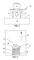
- FIG. 1 is a schematic end view of a single beam turbulator welding system perpendicular to the weld direction in an embodiment of the present disclosure.
- FIG. 2 is a schematic top view of the turbulator welding system of FIG. 1 .
- FIG. 3 is a schematic cross sectional view of an article having a weld turbulator in an embodiment of the present disclosure.
- FIG. 4 is a schematic end view of a dual beam turbulator welding system perpendicular to the weld direction in an embodiment of the present disclosure.
- FIG. 5 is a top view of a weld turbulator formed on an article using a 200-kW laser.
- FIG. 6 is an end view of the weld turbulator and article of FIG. 5 .
- FIG. 7 is a top view of a weld turbulator formed on an article using a 100-kW laser.
- FIG. 8 is an end view of the weld turbulator and article of FIG. 7 .
- a weld turbulator fabrication with a turbulator welding system including an arc welder and at least one beam welder to produce a weld turbulator on the surface of an article.
- Embodiments of the present disclosure for example, in comparison to concepts failing to include one or more of the features disclosed herein, provide a cleaner weld fusion edge, provide a lower contact angle at a fusion edge, provide features of a narrower width and a taller height in a single welding pass, provide better heat transfer at a surface, or combinations thereof.
- Arc welding refers to any process using an electrode to generate an electrical arc to heat a metallic metal for welding.
- the electrode may be a consumable electrode or a non-consumable electrode.
- Consumable electrode methods of arc welding include, but are not limited to, metal/inert-gas (MIG) welding, shielded metal arc welding, flux-cored arc welding, and submerged arc welding.
- Non-consumable methods of arc welding include, but are not limited to, tungsten/inert-gas (TIG) welding, plasma arc welding, atomic hydrogen welding, carbon arc welding, electrogas welding, and stud arc welding.
- Beam welding refers to any process generating a beam to heat a metallic metal for welding. Beam welding processes include, but are not limited to, laser beam welding and electron beam welding.
- Hastelloy X refers to an alloy including a composition, by weight, of between about 8% and about 10% molybdenum (Mo), between about 20.5% and about 23% chromium (Cr), between about 17% and about 20% iron (Fe), between about 0.2% and about 1% tungsten (W), between about 0.5% and about 2.5% cobalt (Co), between about 0.05% and about 0.15% carbon (C), up to about 1% silicon (Si), up to about 1% manganese (Mn), up to about 0.01% boron (B), up to about 0.04% phosphorus (P), up to about 0.03% sulfur (S), incidental impurities, and a balance of nickel (Ni).
- Mo molybdenum
- Cr chromium
- Fe iron
- W between about 0.2% and about 1% tungsten
- Co cobalt
- C carbon
- Si silicon
- Mn manganese
- B up to about 0.04% phosphorus
- S sulfur
- Haynes 282 refers to an alloy including a composition, by weight, of between about 18.5% and about 20.5% Cr, between about 9% and about 11% Co, between about 8% and about 9% Mo, between about 1.9% and about 2.3% titanium (Ti), between about 1.38% and about 1.65% aluminum (Al), up to about 1.5% Fe, up to about 0.3% Mn, up to about 0.15% Si, up to about 0.1% copper (Cu), between about 0.04% and about 0.08% C, up to about 0.02% zirconium (Zr), up to about 0.015% P, up to about 0.015% S, between about 0.003% and about 0.01% B, incidental impurities, and a balance of Ni.
- a composition, by weight of between about 18.5% and about 20.5% Cr, between about 9% and about 11% Co, between about 8% and about 9% Mo, between about 1.9% and about 2.3% titanium (Ti), between about 1.38% and about 1.65% aluminum (Al), up to about 1.5% Fe, up to about 0.3%
- Nimonic 263, as used herein, refers to an alloy including a composition, by weight, of between about 19% and about 21% Cr, between about 19% and about 21% Co, between about 5.6% and about 6.1% Mo, between about 1.9% and about 2.4% Ti, up to about 0.6% Al, up to about 0.6% Mn, up to about 0.4% Si, up to about 0.2% Cu, incidental impurities, and a balance of Ni.
- the turbulator welding system 10 includes an arc welder 12 generating an electric arc 14 , a first beam welder 16 generating a first beam 18 , and a second beam welder 20 generating a second beam 22 .
- the arc welder 12 is located to supply the electric arc 14 between the first beam 18 of the first beam welder 16 and the second beam 22 of the second beam welder 20 .
- the turbulator welding system 10 generates a weld pool 30 and shapes the weld pool 30 to form a weld turbulator 40 on the surface 32 of an article 34 .
- the electric arc 14 forms the weld pool 30
- the first beam 18 shapes a first fusion edge 42 of the weld pool 30
- the second beam 22 shapes a second fusion edge 44 of the weld pool 30
- the first beam 18 and the second beam 22 are placed substantially laterally to the weld pool 30 with respect to the weld direction 50 .
- the arc welder 12 , the first beam welder 16 , and the second beam welder 20 generally move together in a weld direction 50 to form the weld turbulator 40 on the surface 32 of the article 34 .
- the arrangement and movement of the arc welder 12 , the first beam welder 16 , and the second beam welder 20 is coordinated to produce a weld turbulator 40 on the surface 32 of the article 34 that, in addition to having a first fusion edge 42 and a second fusion edge 44 that are smooth, generally has a ridge shape 46 with a turbulator height 60 , a turbulator width 62 , a first turbulator contact angle 64 at the first fusion edge 42 , and a second turbulator contact angle 66 at the second fusion edge 44 .
- the turbulator welding system 10 includes an arc welder 12 generating an electric arc 14 and a first beam welder 16 generating a first beam 18 .
- the electric arc 14 forms a weld pool 30
- the first beam 18 shapes a first fusion edge 42 of the weld pool 30 .
- the arc welder 12 and the first beam welder 16 generally move together in a weld direction 50 to form the weld turbulator 40 on the surface 32 of the article 34 .
- FIG. 5 shows an image of a weld turbulator 40 formed using a turbulator welding system 10 including a MIG welder as the arc welder 12 and a laser welder with a 2-kW laser as the first beam welder 16 on the left edge of the weld turbulator 40 but no second beam welder 20 on the right edge of the weld turbulator 40 .
- the second fusion edge 44 is irregular, with weld toes 48 extending laterally from the weld turbulator 40 .
- the first fusion edge 42 is uniform with a consistent weld width without any surface preparation as a result of use of the first beam welder 16 during formation of the weld turbulator 40 .
- FIG. 6 shows an image of the weld turbulator 40 of FIG. 5 from an end of the weld turbulator 40 .
- the weld turbulator 40 on the surface 32 of the article 34 has a first fusion edge 42 , a second fusion edge 44 , a ridge shape 46 , a turbulator height 60 , and a turbulator width 62 .
- the first turbulator contact angle 64 at the first fusion edge 42 is greater than the second turbulator contact angle 66 at the second fusion edge 44 .
- FIG. 7 shows an image of a weld turbulator 40 formed using a turbulator welding system 10 including a MIG welder as the arc welder 12 and a laser welder with a 1-kW laser as the first beam welder 16 on the left edge of the weld turbulator 40 but no second beam welder 20 on the right edge of the weld turbulator 40 .
- the second fusion edge 44 is irregular, with weld toes 48 extending laterally from the weld turbulator 40 .
- the first fusion edge 42 is uniform with a consistent weld width without any surface preparation as a result of use of the first beam welder 16 during formation of the weld turbulator 40 .
- FIG. 8 shows an image of the weld turbulator 40 of FIG. 7 from an end of the weld turbulator 40 .
- the weld turbulator 40 on the surface 32 of the article 34 has a first fusion edge 42 , a second fusion edge 44 , a ridge shape 46 , a turbulator height 60 , and a turbulator width 62 .
- the first turbulator contact angle 64 at the first fusion edge 42 is similar to the second turbulator contact angle 66 at the second fusion edge 44 at this lower laser beam power. Without being bound by theory, it is believed that the first turbulator contact angle 64 varies with laser beam power and the second turbulator contact angle 66 varies with arc power.
- a minimum laser beam power that is sufficient to assist and form a uniform first fusion edge 42 may be used.
- a greater laser beam power may be used.
- Conventional MIG welding creates shallow weld turbulator 40 profiles, for example, having a turbulator height 60 up to about 0.76 mm (about 0.030′′) with a turbulator width 62 from the first fusion edge 42 to the second fusion edge 44 of about 2.5 mm (about 0.10′′) or less, and surface preparations, such as, for example, removal of a surface oxide layer, removal of surface dirt, or machining of the surface 32 , prior to formation of the weld turbulator 40 may be needed to achieve such dimensions.
- a taller weld turbulator 40 may be achieved by using more weld material but at the cost of a wider weld turbulator 40 .
- a first beam 18 and a second beam 22 hitting on either side of the weld pool 30 assist the weld fusion and create a first fusion edge 42 and a second fusion edge 44 that are smooth, have no weld toes 48 , and have a first turbulator contact angle 64 and a second turbulator contact angle 66 that meet mechanical design specifications for a weld turbulator 40 with higher low-cycle fatigue (LCF).
- the two lateral beams, first beam 18 and second beam 22 may be used to control the turbulator width 62 of the weld turbulator 40 and, indirectly, the turbulator height 60 .
- a smooth first fusion edge 42 and/or a higher first turbulator contact angle 64 are desirable on only one of the first fusion edge 42 and the second fusion edge 44 of the weld turbulator 40 .
- only the upstream side of the weld turbulator 40 has a first fusion edge 42 that is smooth and has a higher first turbulator contact angle 64 by formation using a first beam 18 , whereas the downstream side is formed without a second beam 22 such that the second fusion edge 44 on the downstream side may be irregular, may have weld toes 48 , and/or may have a lower turbulator contact angle 66 , where upstream and downstream are with respect to the direction of fluid flow over the surface 32 during service.
- a single first beam 18 hitting laterally on one side of the weld pool 30 assists the weld fusion and creates a first fusion edge 42 that is smooth, has no weld toes 48 , and has a first turbulator contact angle 64 that meets mechanical design specifications for a weld turbulator 40 with higher low-cycle fatigue (LCF).
- the lateral first beam 18 may be used to control the turbulator width 62 of the weld turbulator 40 and, indirectly, the turbulator height 60 .
- the article 34 is a turbine component. In some embodiments, the article 34 is a turbine combustion component. In some embodiments, the material of the article 34 is a superalloy. In some embodiments, the superalloy is an iron-based superalloy, a cobalt-based superalloy, or a nickel-based superalloy. In some embodiments, the material of the article is Hastelloy X, Haynes 282, or Nimonic 263.
- attaching the weld turbulator 40 to the article 34 provides better cooling and better reinforcement for the component body in a harsh turbine environment with a high temperature and mechanical vibration. The process saves fabrication time and increases productivity.
- the turbulator welding system 10 is fully automated. Parameters, such as the distance between the arc welder 12 and the first beam welder 16 , the distance between the arc welder 12 and the second beam welder 20 , the distance between the first beam welder 16 and the second beam welder 20 , the feed rate of the weld material, and the translation rate of the arc welder 12 , first beam welder 16 , and second beam welder 20 in the weld direction 50 , may be set or adjusted depending on the desired turbulator width 62 , turbulator height 60 , first turbulator contact angle 64 , and second turbulator contact angle 66 of the weld turbulator 40 .
- one or more of the arc welder 12 , the first beam welder 16 , and the second beam welder 20 may be manually controlled.
- the weld turbulator 40 has a turbulator height 60 from the surface 32 of the article 34 to the highest point of the weld turbulator 40 of at least about 2.3 mm (about 0.09′′), alternatively at least about 1.8 mm (about 0.07′′), alternatively at least about 2.0 mm (about 0.08′′), alternatively at least about 2.5 mm (about 0.10′′), alternatively in the range of about 2.0 mm (about 0.08′′) to about 2.5 mm (about 0.10′′), or any value, range, or subrange therebetween, and a turbulator width 62 from the first fusion edge 42 to the second fusion edge 44 of no more than about 0.76 mm (about 0.030′′), alternatively no more than about 0.64 mm (about 0.025′′), alternatively no more than about 0.89 mm (about 0.035′′), alternatively no more than about 1.02 mm (about 0.040′′), alternatively in the range of about 0.64 mm (about 0.025′′) to about 1.02
- the weld turbulator 40 has at least one of the first fusion edge 42 and the second fusion edge 44 having a first turbulator contact angle 64 and/or a second turbulator contact angle 66 , respectively, each of at least about 35 degrees, alternatively at least about 30 degrees, alternatively at least about 40 degrees, alternatively in the range of about 30 degrees to about 40 degrees, or any value, range, or subrange therebetween.
- the weld turbulator 40 is formed in a single pass of the turbulator welding system 10 in the weld direction 50 .
- the dimensions of the weld turbulator 40 are achieved with no machining to change the ridge shape 46 of the weld turbulator 40 after its initial formation by the welding process.
- the formed structure has been described herein as a weld turbulator 40 , the formed structure may have any application where a buildup weld structure having a uniform edge, a high contact angle, and/or the combination of height and width achievable by the welding process is desirable.
Landscapes
- Engineering & Computer Science (AREA)
- Physics & Mathematics (AREA)
- Mechanical Engineering (AREA)
- Optics & Photonics (AREA)
- Plasma & Fusion (AREA)
- General Engineering & Computer Science (AREA)
- Chemical & Material Sciences (AREA)
- Materials Engineering (AREA)
- Laser Beam Processing (AREA)
- Welding Or Cutting Using Electron Beams (AREA)
Abstract
Description
Claims (9)
Priority Applications (1)
| Application Number | Priority Date | Filing Date | Title |
|---|---|---|---|
| US15/631,131 US10434601B2 (en) | 2017-06-23 | 2017-06-23 | Welding process with an arc welder and beam welder for a weld turbulator |
Applications Claiming Priority (1)
| Application Number | Priority Date | Filing Date | Title |
|---|---|---|---|
| US15/631,131 US10434601B2 (en) | 2017-06-23 | 2017-06-23 | Welding process with an arc welder and beam welder for a weld turbulator |
Publications (2)
| Publication Number | Publication Date |
|---|---|
| US20180369962A1 US20180369962A1 (en) | 2018-12-27 |
| US10434601B2 true US10434601B2 (en) | 2019-10-08 |
Family
ID=64691368
Family Applications (1)
| Application Number | Title | Priority Date | Filing Date |
|---|---|---|---|
| US15/631,131 Active 2038-01-23 US10434601B2 (en) | 2017-06-23 | 2017-06-23 | Welding process with an arc welder and beam welder for a weld turbulator |
Country Status (1)
| Country | Link |
|---|---|
| US (1) | US10434601B2 (en) |
Citations (5)
| Publication number | Priority date | Publication date | Assignee | Title |
|---|---|---|---|---|
| US5353865A (en) * | 1992-03-30 | 1994-10-11 | General Electric Company | Enhanced impingement cooled components |
| JP2003311456A (en) * | 2002-04-19 | 2003-11-05 | Daihen Corp | Laser beam irradiating arc welding head |
| US20150165547A1 (en) * | 2013-12-12 | 2015-06-18 | General Electric Company | Fabrication process and fabricated article |
| US20150328719A1 (en) * | 2012-12-21 | 2015-11-19 | European Space Agency | Additive manufacturing method using focused light heating source |
| US20170145586A1 (en) * | 2015-11-23 | 2017-05-25 | Hobart Brothers Company | System and method for single crystal growth with additive manufacturing |
-
2017
- 2017-06-23 US US15/631,131 patent/US10434601B2/en active Active
Patent Citations (5)
| Publication number | Priority date | Publication date | Assignee | Title |
|---|---|---|---|---|
| US5353865A (en) * | 1992-03-30 | 1994-10-11 | General Electric Company | Enhanced impingement cooled components |
| JP2003311456A (en) * | 2002-04-19 | 2003-11-05 | Daihen Corp | Laser beam irradiating arc welding head |
| US20150328719A1 (en) * | 2012-12-21 | 2015-11-19 | European Space Agency | Additive manufacturing method using focused light heating source |
| US20150165547A1 (en) * | 2013-12-12 | 2015-06-18 | General Electric Company | Fabrication process and fabricated article |
| US20170145586A1 (en) * | 2015-11-23 | 2017-05-25 | Hobart Brothers Company | System and method for single crystal growth with additive manufacturing |
Also Published As
| Publication number | Publication date |
|---|---|
| US20180369962A1 (en) | 2018-12-27 |
Similar Documents
| Publication | Publication Date | Title |
|---|---|---|
| JP5607031B2 (en) | Manufacture of parts of metal parts using MIG method with pulsed current and wire | |
| KR101791976B1 (en) | Localized repair of superalloy component | |
| US9283593B2 (en) | Selective laser melting / sintering using powdered flux | |
| JP6104408B2 (en) | Method for forming a cladding layer of a superalloy material | |
| US9315903B2 (en) | Laser microcladding using powdered flux and metal | |
| KR101791113B1 (en) | Deposition of superalloys using powdered flux and metal | |
| US20160279734A1 (en) | Component and method for fabricating a component | |
| US20130140278A1 (en) | Deposition of superalloys using powdered flux and metal | |
| JP2018537288A (en) | Method for joining two blanks and method for forming a product | |
| EP2950950A1 (en) | Selective laser melting / sintering using powdered flux | |
| KR20150106007A (en) | Localized repair of superalloy component | |
| EP3560649A1 (en) | Laser hot wire welding of multi-layered structures | |
| CN105408056A (en) | Repair of a substrate with component supported filler | |
| EP2596896A1 (en) | Welding system and process with a laser device, a GMAW device and a GTAW device; corresponding welded article | |
| WO2014120511A1 (en) | Hybrid laser plus submerged arc or electroslag cladding of superalloys | |
| CN104955983A (en) | Laser micro cladding using powder flux and metal | |
| JPWO2019160141A1 (en) | Resistance spot welding method and method for manufacturing welded member | |
| CN104511702A (en) | Welding material for welding of superalloys | |
| US10434601B2 (en) | Welding process with an arc welder and beam welder for a weld turbulator | |
| Anirudhan et al. | Manufacturing of a bimetallic structure of stainless steel and mild steel through wire arc additive manufacturing—a critical review | |
| US20130086911A1 (en) | Process and apparatus for overlay welding | |
| Magadum et al. | Developments and improvements using hot wire gas tungsten arc welding–A review | |
| Gowthaman et al. | Effect on Various Parameter of Stainless Steel 316L Weld Bead Geometry using Cold Metal Transfer (CMT) Process. | |
| CN119489273B (en) | A welding method for nickel-based alloy composite plates | |
| KR102921541B1 (en) | Method for Filler-Free Joining of Difficult-to-Weld Material Components |
Legal Events
| Date | Code | Title | Description |
|---|---|---|---|
| AS | Assignment |
Owner name: GENERAL ELECTRIC COMPANY, NEW YORK Free format text: ASSIGNMENT OF ASSIGNORS INTEREST;ASSIGNOR:LIN, DECHAO;REEL/FRAME:042976/0375 Effective date: 20170622 |
|
| STPP | Information on status: patent application and granting procedure in general |
Free format text: NON FINAL ACTION MAILED |
|
| STPP | Information on status: patent application and granting procedure in general |
Free format text: RESPONSE TO NON-FINAL OFFICE ACTION ENTERED AND FORWARDED TO EXAMINER |
|
| STPP | Information on status: patent application and granting procedure in general |
Free format text: EX PARTE QUAYLE ACTION MAILED |
|
| STPP | Information on status: patent application and granting procedure in general |
Free format text: RESPONSE TO EX PARTE QUAYLE ACTION ENTERED AND FORWARDED TO EXAMINER |
|
| STPP | Information on status: patent application and granting procedure in general |
Free format text: NOTICE OF ALLOWANCE MAILED -- APPLICATION RECEIVED IN OFFICE OF PUBLICATIONS |
|
| STPP | Information on status: patent application and granting procedure in general |
Free format text: PUBLICATIONS -- ISSUE FEE PAYMENT VERIFIED |
|
| STCF | Information on status: patent grant |
Free format text: PATENTED CASE |
|
| MAFP | Maintenance fee payment |
Free format text: PAYMENT OF MAINTENANCE FEE, 4TH YEAR, LARGE ENTITY (ORIGINAL EVENT CODE: M1551); ENTITY STATUS OF PATENT OWNER: LARGE ENTITY Year of fee payment: 4 |
|
| AS | Assignment |
Owner name: GE INFRASTRUCTURE TECHNOLOGY LLC, SOUTH CAROLINA Free format text: ASSIGNMENT OF ASSIGNORS INTEREST;ASSIGNOR:GENERAL ELECTRIC COMPANY;REEL/FRAME:065727/0001 Effective date: 20231110 |