US1043422A - Sewing-machine. - Google Patents
Sewing-machine. Download PDFInfo
- Publication number
- US1043422A US1043422A US59907410A US1910599074A US1043422A US 1043422 A US1043422 A US 1043422A US 59907410 A US59907410 A US 59907410A US 1910599074 A US1910599074 A US 1910599074A US 1043422 A US1043422 A US 1043422A
- Authority
- US
- United States
- Prior art keywords
- arm
- rod
- raceway
- cam
- sewing
- Prior art date
- Legal status (The legal status is an assumption and is not a legal conclusion. Google has not performed a legal analysis and makes no representation as to the accuracy of the status listed.)
- Expired - Lifetime
Links
- 230000007246 mechanism Effects 0.000 description 10
- 238000009958 sewing Methods 0.000 description 10
- 238000010276 construction Methods 0.000 description 5
- 230000003534 oscillatory effect Effects 0.000 description 3
- 239000011435 rock Substances 0.000 description 2
- 230000015572 biosynthetic process Effects 0.000 description 1
- 230000000994 depressogenic effect Effects 0.000 description 1
- 239000000463 material Substances 0.000 description 1
- 235000012054 meals Nutrition 0.000 description 1
- 230000000284 resting effect Effects 0.000 description 1
- 230000000717 retained effect Effects 0.000 description 1
- 230000000630 rising effect Effects 0.000 description 1
Images



Classifications
-
- D—TEXTILES; PAPER
- D05—SEWING; EMBROIDERING; TUFTING
- D05B—SEWING
- D05B1/00—General types of sewing apparatus or machines without mechanism for lateral movement of the needle or the work or both
- D05B1/02—General types of sewing apparatus or machines without mechanism for lateral movement of the needle or the work or both for making single-thread seams
- D05B1/06—Single chain-stitch seams
Definitions
- My invention relates to improvements in machines designed more especially for sewing patches on bags of various kinds, and resides in the parts and combinations of parts required to make up and render effective a machine of this type, all as hereinafter set forth.
- Bags for holding grain, meal, and other kinds of feed, and many bags for other purposes, are usually of coarse and comparatively cheap material, and since they undergo very rough usage need patching, frequently, otherwise they would have to be thrown away on account of the holes in them.
- a further object is to provide a sewing machine, for the purpose above set forth,
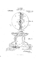
- FIG. 1 is a top plan, without the arm and its appurtenances, of a sewing-machine in which is embodied a practicalform of my invention
- Fig. 2 a top plan of certain of the shuttle-carrier-operating and feed-operating members
- Fig. 3 a right-hand side elevation of the sewing-machine complete, excepting that a portion of the table is broken away, the driving shaft is in section and some of the driving members on that side of the machine are omitted
- Fig. 4 a left-hand side elevation and partial section of said machine, the section being through the table, the driving shaft and one of the cams on such shaft
- Fig. 5 a detail of the Specification of Letters l atent.
- Fig. 6 an enlarged top plan of the stand and its members, the shuttle raceway being open;
- Fig. 7 an enlarged vertical section through said stand, taken on lines 77, looking in the direction of the associated arrow, in Fig. 6, and showing in detail the feed device;
- Fig. 8, an enlarged top plan of said feed device, and, Fig. 9, an enlarged vertical section taken on lines 9-9, looking in the direction of the associated arrow, in Fig. 6.
- This sewing-machine consists in part of a suitable table 1, which may be supported or upheld in any convenient manner and by any appropriate means, and has mounted on and securely attached to it an arm 2, of ordinary construction, and a hollow stand 3, the latter being located directly beneath the front end or head of said arm.
- the sewing is done on the stand 3, hence said stand is of the proper size, shape and height to accommodate to good advantage the article being sewed, and it has a flat top which eX- tends beyond the barrel or body portion of said stand all the way around.
- an opening 4 shown in Figs. 7 and 9
- an opening or slot 5 in said table which extends through the base of the upright portion of the arm 2, as shown in Figs. 1 and 2, and still another opening or slot 6 in said table at the left of said base, as shown in Figs. 1 and 4.
- the main driving shaft 8 is journaled in the upright part of the arm 2 and in bearings 10--10 fastened to the top of the table 1.
- a hand-wheel 11 Secured on the right-hand terminal of the shaft 8 is a hand-wheel 11, for operating the mechanism by hand, and tight and loose pulleys l2 and 13, said hand-wheel and said pulleys being beyond the adjacent bearing 10; and between said bearing and the upright portion of the arm 2 is a cam 14 having a cam groove 15 therein, and an eccentric 16 having an offset, shoulder or step 17 extending across its periphery, said cam and said eccentric being, of course, tight on said shaft.
- a cam 18 Secured to the shaft 8 between the left-hand bearing 10 and the upright portion of the arm 2 is a cam 18 having a groove 19 therein.
- the machine is driven by means of a belt (not shown) which transmits power to the tight pulley 12 from any suitable source.
- the hand-wheel 11 serves the usual purpose of hand-wheels in other classes of sewing-machines
- the arm 2 is provided at the back with a support 20 for a spool 21, and at the front or head end with a vertically-reciprocating rod'22 in the base of which a needle 23 is received, and with a vertically-movable rod 24 having a resser-foot 25 attached to the bottom thereof.
- the rods 22 and 24 are niov'ably mounted in the headof the arm 3 in the usual manner in machines in this class.
- Thread 26 passes forward from the spool 21 under and through a simple tension spring 27 on top of the arm 2, over the top of the head of'said arm and around a guide 28 attached to the front of said head and back over said head again, down and backward to and through the free end of a finger 29 pivotally attached at 30 to the right-hand side of said arm, and then forward t'othe base of the rod 22 and through an opening therein and downward to and through the eye in the needle 23.
- the object of the finger 29 is to draw offsuflicient slack thread 26 from the spool'21, when the needle ascends, to supply said needle with ample thread with whichto make the stitch, when next said needle descends.
- a rocker a'rm 32 Projecting to the right from the arm 2is a stud 31, and mounted on this stud is a rocker a'rm 32 which has its rear end pivotallyconnect'ed at 33 with a connecting-rod 34', andhas its front end pivotally connected by means of an angular link 35 with the upper terminal of the rod 22, the base of said link being pivoted at 36 to said rockerarm and the other end of said link being pivoted at 37 to said rod.
- adjustable bearings are provided for the pivotal members 31, 33 and 36, so that the necessary degree of accuracy in the stroke of the needle may be obtained.
- the rockerarm 32 is provided with two lugs 38, one above and one below said stud, and with adjusting bolts 3939 tapped into and through such lugs, and two bearing-blocks 40 are placed on said stud between said screws.
- Similar bearing blocks 40 are provided for the pivot 33, also for the pivot 36. In the former case adjustment is effected by means of a bolt 41 tapped into and through the upper end of the connecting-rod 34, above the blocks 40, and a bolt 42 tapped into said rod below said blocks.
- pivot 36 Similar members are provided and a similar adjustment afforded for the pivot 36, in this case the bolt 41 being tapped into and through the bottom of the link 35, below the bearing blocks 40, and the bolt 42 being tapped into said link above said blocks. Adjustment of either the pivot 33, or the pivot 36, is effected in practically the same manner as that previously noted in connection with the stud 31.
- the base of the connecting-rod 34 is in the form of a band 43 which fits the eccentric 16. Vithin this band 43 is a transverse shoulder or step 44 which corresponds with the step 17 and cooperates therewith in the manner hereinafter explained.
- connecting-rod 34 In order to render the steps 17 and 44 effective means must be provided for forcing the connecting-rod 34 downward, such, for example, as a spring 100 attached to a lug 101 on the arm and arranged to bear against the underside of the rockei arm 32 in advance of its pivotal stud 31. This spring tends to force the forward part of the rockerarm 32 upward and the rear end of said arm with the connecting-rod 34 downward.
- a spring 100 attached to a lug 101 on the arm and arranged to bear against the underside of the rockei arm 32 in advance of its pivotal stud 31.
- This spring tends to force the forward part of the rockerarm 32 upward and the rear end of said arm with the connecting-rod 34 downward.
- a pin 46 In the upper terminal of the finger 29 is a slot 45 and a pin 46 extends from the right-hand side of the rocker-arm 32 into said slot.
- the resser-foot rod 24 has a pin 47 which plays up and down in a groove 48, in the head of the arm 2, and so prevents said rod from turning in said head, and said rod also has a slot 49 into which is received the free terminal of a spring 50 which is attached at 51 to the left-hand side of the arm 2, the arrangement being such that said spring eX- erts a force constantly tending to depress said rod.
- a sleeve 52 On the upper end of the rod 24, above the head of the arm 2, is a sleeve 52 which is cut away at 53 and is provided with a handle 54. The cut-away portion of the sleeve 52 forms a cam 55 for a pin 56 which projects laterally from said rod.
- a serrated feedmember 57 Operatively located directly beneath the presser-foot 25, in approximately the center of the top of the stand 3, is a serrated feedmember 57.
- This member is bifurcated and has a downwardly-extending piece which is attached by a bolt 58 to a plate 59.
- a plate 60 is let into the center of the top of the stand 3, and this plate is cut out to receive the feed-member 57 and has an opening 61 therein through which the point of the needle 23 passes when said needle descends.
- the plate 59 is adapted to reciprocate against the back side of the raceway 62 and behind the same, being held up at one end by means of a stud or screw 63 which passes through a slot 64 in said plate into the rear wall of said raceway, and at the other end by means of a rearwardly-extending pin 65 and a rocker-arm 66.
- the top of the stand 3 is cut out at 67 to permit the feed-member 57 to move to the left as far as may be required, and two slides 68 and 69 are provided to close the raceway 62 each side of the plate 60, the slide 69 being cut away at 94 also for the purpose of accommodating said feed-member.
- the raceway 62 is provided for a shuttle 70 of usual construction and functioning in the customary manner.
- a carrier 71 for the shuttle 70 is provided, and this carrier has a longitudinal groove 72 therein which receives the upper edge of the front side of the raceway 62.
- the carrier 71 reciprocates on the front side of the raceway 62 and below the plane of the underside of the top of the stand 3.
- the back side of the carrier 71 is hollowed out to receive the front side of the shuttle 70, as best shown in Fig. 6, and so forms a close union with said shuttle and causes the same to travel with it with the rear flat side of said shuttle against the back side of said raceway.
- the rocker-arm 66 is forked at is upper end to receive the pin 65, and the bottom of this forked portion is stepped as shown at 75 and 76.
- the arm 66 rocks it carries the plate 59 with it and at the same time raises and lowers the left-hand end of said plate, as the pin 65 ridesfrom one step to the other, and consequently tilts the feed-member 57 and projects the corresponding end of said member well above the top of the stand 3 and withdraws it again.
- This movement or these movements of the feedmember 57 actuate the bag being sewed onward on the stand 3 for the next stitch, the presser-foot 25 being down on said member to hold the bag from above and prevent it from going with the feed-member when the latter travels to the left in order to get a fresh grasp on the bag.
- the feedmember 57 is in its normal or horizontal position, only the teeth thereon project above the stand top.
- Motion is imparted to the rocker-arm 66, from the cam 18, through the medium of a horizontal rock-shaft 77 journaled in bearings 78-78 fastened to the underside of the table 1, an upstanding arm 79 having its base secured to said rock-shaft and provided at its upper end with a horizontal projection or pin 80 which enters the camgroove 19.
- the cam-groove 19 is provided with a single offset, so that the rocker-arm and the feed-member 57 have but one impulse imparted to them at each revolution of the cam 18.
- the base of the rod 74 is received into a slide 81 mounted on a horizontal fixed rod 82 which is supported in hangers 83S3 secured to the underside of the table 1, and said slide is reciprocated by means of a horizontal lever St pivotally mounted, in termediate of its ends, at 85, beneath the table 1, and having its rear end operatively connected with the cam 1-lby means of a horizontal link 8", a horizontal arm 87 and a vertical projection or pin 88.
- the front end of the lever 84 is received in a recess in the slide 81, such recess being best shown at 89 in Fig. 7, and is free to move therein so as to actuate the slide as said lever is actuated.
- the link 86 has one end pivoted at 90 to the rear end of the lever 84, and the other end pivoted at 91, F 3, to the arm 87.
- the arm 87 has its rear end piv oted at 92 to the top of the table 1.
- the axis of the pin 88 is in line with the axis of the pivot 91..
- a spring may be introduced between the arm 87 and the adjacent bearing 10 for the pi'lrpose of compensating for wear on the part of the pin 88 and the cam-groove 15 into which said pin extends from below, said spring having a constant tendency to force said arm and its pivotally connected members, back of the pivot 85, toward the left.
- the pivot 91 extends through and operates in the slot 5
- the arm 79 extends through and operates in the slot 6
- the rocker-arm 6G and the rod Tat extend through and operate in the opening 4, all in the table 1.
- the bag to be patched is placed on the table 1, with the partto be repaired or covered stretched on or laid smoothly on the top of the stand 3 and drawn down around the surrounding flange at such top, the patch is placed over the hole or worn part in said bag, the presser-foot is let down by means of the sleeve 52, and
Landscapes
- Engineering & Computer Science (AREA)
- Textile Engineering (AREA)
- Sewing Machines And Sewing (AREA)
Description
A. W. HESCOGK.
SEWING MACHINE.
APPLICATION PILEDDEO. 24, 1910.
1,048A22Q Patented Nov. 5, 1912.
' 4 SHEETS-SHEET 1.
. 1 VENTOR.
7 ATTORNEYS.
OLUMBIA PLANOGRAPH 60-. WASHINGTON D c A. W. HESGOUK.
SEWING MACHINE. APPLICATION FILED DEC. 24, 1910.
1,043,422. Patented Nov. 5, 1912.
4 SHEETS-SHEET 2.
%MW; W
LOLUMBIA FLANOORAPH CO WASHINGTON D. e.
A. W. HESOOGK. SEWING MACHINE. APPLIUATION IILFD DEG. 24, 1910.
.1 43,422. Patented Nov. 5, 1912. I
4 SHEETSSHEET 3.
V 77 WITNESSES:
COLUMBIA PLANOGRAPII c0.,\\'.\s|ilNuToN. D. u.
A. W. HESGOGK. SEWING MACHINE. APPLICATION FILED DEC. 24, 1910.
Patented Nov. 5, 1912.
4 SHEETS-SHEET 4.
WfT/VESSES- UNITED STATES Parana @FFTCE.
ALVIN W. HESCOCK, OF HUNTINGTON, MASSACHUSETTS.
SEWING-MACHINE.
To all whom it may concern:
Be it known that I, ALVIN W. Hnscoon, a citizen of the United States of America, residing at Huntington, in the county of Hampshire and State of Massachusetts, have invented a new and useful Sewing-Machine, of which the following is a specification.
My invention relates to improvements in machines designed more especially for sewing patches on bags of various kinds, and resides in the parts and combinations of parts required to make up and render effective a machine of this type, all as hereinafter set forth.
Bags for holding grain, meal, and other kinds of feed, and many bags for other purposes, are usually of coarse and comparatively cheap material, and since they undergo very rough usage need patching, frequently, otherwise they would have to be thrown away on account of the holes in them.
This work of patching has heretofore been done by hand, and the primary object of my inventionis to produce a machine for sewing on these patches in a more economical, expeditious and efficient manner than can be done by hand.
A further object is to provide a sewing machine, for the purpose above set forth,
, which ,is comparatively inexpensive, is simple in construction and operation, has few parts, is not liable to get out of order, and withal is entirely practicable and efficient for the work for which itis intended.
Other objects will appear in the course of the following description. 7
I attain these objects by the mechanism illustrated in the accompanying drawings, in which- Figure 1. is a top plan, without the arm and its appurtenances, of a sewing-machine in which is embodied a practicalform of my invention; Fig. 2, a top plan of certain of the shuttle-carrier-operating and feed-operating members; Fig. 3, a right-hand side elevation of the sewing-machine complete, excepting that a portion of the table is broken away, the driving shaft is in section and some of the driving members on that side of the machine are omitted; Fig. 4, a left-hand side elevation and partial section of said machine, the section being through the table, the driving shaft and one of the cams on such shaft; Fig. 5, a detail of the Specification of Letters l atent.
Application filed December 24, 1910.
Patented Nov. 5, 1912.
Serial No. 599,074.
presser-foot lifter; Fig. 6, an enlarged top plan of the stand and its members, the shuttle raceway being open; Fig. 7 an enlarged vertical section through said stand, taken on lines 77, looking in the direction of the associated arrow, in Fig. 6, and showing in detail the feed device; Fig. 8, an enlarged top plan of said feed device, and, Fig. 9, an enlarged vertical section taken on lines 9-9, looking in the direction of the associated arrow, in Fig. 6.
Similar figures refer to similar parts throughout the several views.
This sewing-machine consists in part of a suitable table 1, which may be supported or upheld in any convenient manner and by any appropriate means, and has mounted on and securely attached to it an arm 2, of ordinary construction, and a hollow stand 3, the latter being located directly beneath the front end or head of said arm. The sewing is done on the stand 3, hence said stand is of the proper size, shape and height to accommodate to good advantage the article being sewed, and it has a flat top which eX- tends beyond the barrel or body portion of said stand all the way around. By thus eX- tending the top of the stand 3 and providing an annular flange, provision is made for conveniently holding the bag being patched to the stand, and for moving the bag about on the top of the stand as is necessary in the act of sewing on a patch.
In the table 1 below the stand 3 is an opening 4, shown in Figs. 7 and 9, and there is also an opening or slot 5 in said table which extends through the base of the upright portion of the arm 2, as shown in Figs. 1 and 2, and still another opening or slot 6 in said table at the left of said base, as shown in Figs. 1 and 4.
The main driving shaft 8 is journaled in the upright part of the arm 2 and in bearings 10--10 fastened to the top of the table 1. Secured on the right-hand terminal of the shaft 8 is a hand-wheel 11, for operating the mechanism by hand, and tight and loose pulleys l2 and 13, said hand-wheel and said pulleys being beyond the adjacent bearing 10; and between said bearing and the upright portion of the arm 2 is a cam 14 having a cam groove 15 therein, and an eccentric 16 having an offset, shoulder or step 17 extending across its periphery, said cam and said eccentric being, of course, tight on said shaft. Secured to the shaft 8 between the left-hand bearing 10 and the upright portion of the arm 2 is a cam 18 having a groove 19 therein. The machine is driven by means of a belt (not shown) which transmits power to the tight pulley 12 from any suitable source. The hand-wheel 11 serves the usual purpose of hand-wheels in other classes of sewing-machines.
The arm 2 is provided at the back with a support 20 for a spool 21, and at the front or head end with a vertically-reciprocating rod'22 in the base of which a needle 23 is received, and with a vertically-movable rod 24 having a resser-foot 25 attached to the bottom thereof. The rods 22 and 24 are niov'ably mounted in the headof the arm 3 in the usual manner in machines in this class. Thread 26 passes forward from the spool 21 under and through a simple tension spring 27 on top of the arm 2, over the top of the head of'said arm and around a guide 28 attached to the front of said head and back over said head again, down and backward to and through the free end of a finger 29 pivotally attached at 30 to the right-hand side of said arm, and then forward t'othe base of the rod 22 and through an opening therein and downward to and through the eye in the needle 23. The object of the finger 29 is to draw offsuflicient slack thread 26 from the spool'21, when the needle ascends, to supply said needle with ample thread with whichto make the stitch, when next said needle descends.
Projecting to the right from the arm 2is a stud 31, and mounted on this stud is a rocker a'rm 32 which has its rear end pivotallyconnect'ed at 33 with a connecting-rod 34', andhas its front end pivotally connected by means of an angular link 35 with the upper terminal of the rod 22, the base of said link being pivoted at 36 to said rockerarm and the other end of said link being pivoted at 37 to said rod. Preferably, adjustable bearings are provided for the pivotal members 31, 33 and 36, so that the necessary degree of accuracy in the stroke of the needle may be obtained. As an adjustment at the stud 31, the rockerarm 32 is provided with two lugs 38, one above and one below said stud, and with adjusting bolts 3939 tapped into and through such lugs, and two bearing-blocks 40 are placed on said stud between said screws. It will now be readily seen that, by changing the positions of the bolts 39, the pivotal center or axis of the rocker-arm 32 is changed accordingly. Similar bearing blocks 40 are provided for the pivot 33, also for the pivot 36. In the former case adjustment is effected by means of a bolt 41 tapped into and through the upper end of the connecting-rod 34, above the blocks 40, and a bolt 42 tapped into said rod below said blocks. Similar members are provided and a similar adjustment afforded for the pivot 36, in this case the bolt 41 being tapped into and through the bottom of the link 35, below the bearing blocks 40, and the bolt 42 being tapped into said link above said blocks. Adjustment of either the pivot 33, or the pivot 36, is effected in practically the same manner as that previously noted in connection with the stud 31. The base of the connecting-rod 34 is in the form of a band 43 which fits the eccentric 16. Vithin this band 43 is a transverse shoulder or step 44 which corresponds with the step 17 and cooperates therewith in the manner hereinafter explained. In order to render the steps 17 and 44 effective means must be provided for forcing the connecting-rod 34 downward, such, for example, as a spring 100 attached to a lug 101 on the arm and arranged to bear against the underside of the rockei arm 32 in advance of its pivotal stud 31. This spring tends to force the forward part of the rockerarm 32 upward and the rear end of said arm with the connecting-rod 34 downward. In the upper terminal of the finger 29 is a slot 45 and a pin 46 extends from the right-hand side of the rocker-arm 32 into said slot.
as the eccentric 1G is revolved, in the direction of the arrow in Fig. 3, it reciprocates the connecting-rod 34 and so oscillates the rocker-arm 32 and operates the rod 22 with the needle 23, and every time thes'houlder or step 17 on said eccentric passes beneath the shoulder or step 44 within the band 43 a slight upward impulse is given to said needle owing to the presence of the spring 100 and because said band, which is raised by said eccentric to its highest position at this time, drops a little when said step 17 rides from beneath said step 44. hen the long diameter of the eccentric 16 is beneath the upper part of the band 43, the forward terminal of the rocker-arm 32 with the needleis depressed, and the aforesaid upward impulse occurs at the end of this clownward stroke of the needle, and thus insures the formation of the loop in the thread necessary for the passage of the shuttle in the making of the lock-stitch, which is the stitch produced by this machine. After the impulse just described takes place the needle rises-to its highest position, as the eccentric 16continues to revolve. An oscil latory movement is imparted from the rocker-arm 32 to the finger 29, by means of the pin 46 operating in the slot 45, and the parts are .so timed that the lower terminal of said finger moves rearwardly with the thread as the portion of said rocker-arm in front of the pivot 31 rises, and moves for wardly to release the thread to the descending needle as the aforesaid part of said rocker-arm descends. The proper timing of the parts depends largely, of course, upon the relative positions of the eccentric 16 and the connecting-rod 34.
The resser-foot rod 24 has a pin 47 which plays up and down in a groove 48, in the head of the arm 2, and so prevents said rod from turning in said head, and said rod also has a slot 49 into which is received the free terminal of a spring 50 which is attached at 51 to the left-hand side of the arm 2, the arrangement being such that said spring eX- erts a force constantly tending to depress said rod. On the upper end of the rod 24, above the head of the arm 2, is a sleeve 52 which is cut away at 53 and is provided with a handle 54. The cut-away portion of the sleeve 52 forms a cam 55 for a pin 56 which projects laterally from said rod. When the sleeve 52 is in the position shown in Figs. 4 and 5, the pin 56 is resting in a concavity provided for its reception at the top of the cam 55, and the rod 24 is elevated and retained with the presser-foot 24 in its raised position. To release the presser-foot 25 to the spring 50, swing the handle 54 forward and so allow the pin 56 to travel down the cam 55 and the rod 24 to descend under the influence of said spring. To elevate said presser-foot again, swing the arm 54 back into its former position and so forcibly actuate the cam 55 beneath the pin 56, with the result that said pin and the rod 24 are carried upwardly, against the resiliency of the spring 50, until said pin comes to rest in the previously-mentioned concavity at the upper end of said cam. These operations are made possible inasmuch as the pin 47 prevents the rod 24 from rotating.
Operatively located directly beneath the presser-foot 25, in approximately the center of the top of the stand 3, is a serrated feedmember 57. This member is bifurcated and has a downwardly-extending piece which is attached by a bolt 58 to a plate 59. A plate 60 is let into the center of the top of the stand 3, and this plate is cut out to receive the feed-member 57 and has an opening 61 therein through which the point of the needle 23 passes when said needle descends. Extending through the stand 3 from right to left and just in front of the central diameter of said stand, which extends in the aforesaid direction, and opening through the top of the stand, is a shuttle raceway 62. The plate 59 is adapted to reciprocate against the back side of the raceway 62 and behind the same, being held up at one end by means of a stud or screw 63 which passes through a slot 64 in said plate into the rear wall of said raceway, and at the other end by means of a rearwardly-extending pin 65 and a rocker-arm 66. The top of the stand 3 is cut out at 67 to permit the feed-member 57 to move to the left as far as may be required, and two slides 68 and 69 are provided to close the raceway 62 each side of the plate 60, the slide 69 being cut away at 94 also for the purpose of accommodating said feed-member.
The raceway 62 is provided for a shuttle 70 of usual construction and functioning in the customary manner. A carrier 71 for the shuttle 70 is provided, and this carrier has a longitudinal groove 72 therein which receives the upper edge of the front side of the raceway 62. The carrier 71 reciprocates on the front side of the raceway 62 and below the plane of the underside of the top of the stand 3. The back side of the carrier 71 is hollowed out to receive the front side of the shuttle 70, as best shown in Fig. 6, and so forms a close union with said shuttle and causes the same to travel with it with the rear flat side of said shuttle against the back side of said raceway. In the part of the carrier 71 which projects over in front of the raceway 62, at the top, is an opening 73 into which is received the upper end of a vertical rod 74. The rod 74 receives its movement from the cam 14 in the manner presently to be explained.
The rocker-arm 66 is forked at is upper end to receive the pin 65, and the bottom of this forked portion is stepped as shown at 75 and 76. As the arm 66 rocks it carries the plate 59 with it and at the same time raises and lowers the left-hand end of said plate, as the pin 65 ridesfrom one step to the other, and consequently tilts the feed-member 57 and projects the corresponding end of said member well above the top of the stand 3 and withdraws it again. In other words, when the rockerarm 66 moves to the left it elevates the feed-member 57, as the higher step 75 passes beneath the pin 65, and at the same time, with its forked terminal, moves said member into the slot 67, the plate 59 sliding on the screw 63 in the slot 64; then, when said arm rocks to the right, said pin rides off of the step 75 and down on to the step 76, and said feed-member is carried in the same direction by the fork, to the end of the opening therefor in the plate 60. This movement or these movements of the feedmember 57 actuate the bag being sewed onward on the stand 3 for the next stitch, the presser-foot 25 being down on said member to hold the bag from above and prevent it from going with the feed-member when the latter travels to the left in order to get a fresh grasp on the bag. \Vhen the feedmember 57 is in its normal or horizontal position, only the teeth thereon project above the stand top.
Motion is imparted to the rocker-arm 66, from the cam 18, through the medium of a horizontal rock-shaft 77 journaled in bearings 78-78 fastened to the underside of the table 1, an upstanding arm 79 having its base secured to said rock-shaft and provided at its upper end with a horizontal projection or pin 80 which enters the camgroove 19. The cam-groove 19 is provided with a single offset, so that the rocker-arm and the feed-member 57 have but one impulse imparted to them at each revolution of the cam 18.
The base of the rod 74: is received into a slide 81 mounted on a horizontal fixed rod 82 which is supported in hangers 83S3 secured to the underside of the table 1, and said slide is reciprocated by means of a horizontal lever St pivotally mounted, in termediate of its ends, at 85, beneath the table 1, and having its rear end operatively connected with the cam 1-lby means of a horizontal link 8", a horizontal arm 87 and a vertical projection or pin 88. The front end of the lever 84 is received in a recess in the slide 81, such recess being best shown at 89 in Fig. 7, and is free to move therein so as to actuate the slide as said lever is actuated. The link 86 has one end pivoted at 90 to the rear end of the lever 84, and the other end pivoted at 91, F 3, to the arm 87. The arm 87 has its rear end piv oted at 92 to the top of the table 1. The axis of the pin 88 is in line with the axis of the pivot 91.. A spring may be introduced between the arm 87 and the adjacent bearing 10 for the pi'lrpose of compensating for wear on the part of the pin 88 and the cam-groove 15 into which said pin extends from below, said spring having a constant tendency to force said arm and its pivotally connected members, back of the pivot 85, toward the left. The pivot 91 extends through and operates in the slot 5, the arm 79 extends through and operates in the slot 6, and the rocker-arm 6G and the rod Tat extend through and operate in the opening 4, all in the table 1.
From the foregoing it will be plainly seen that, as the cam 14: revolves, it in'iparts an oscillatory movement to the lever 84%., through the medium of the pin 88, the arm 87 and the link 86, and so causes the carrier 71 and the shuttle to reciprocate in the raceway 62, tl'n'ough the medium of the slide 81 and the rod 74. The movement of the slnittle-operating mechanism must be timed, of course, to that of the needle-operating mechanisn'i, and the feed-memberoperating mechanism must be timed to the other two, so that the stitch can be taken in the bag at the proper instant, and the bag advanced for the next stitch at the proper instant.
In practice, the bag to be patched is placed on the table 1, with the partto be repaired or covered stretched on or laid smoothly on the top of the stand 3 and drawn down around the surrounding flange at such top, the patch is placed over the hole or worn part in said bag, the presser-foot is let down by means of the sleeve 52, and
the machine is startecL-then the operation of stitching is carried on in very much the same way as in other types of sewingmachines. A further detailed description of the operation of the several mechanisms hereinbefore described, or of the machine as a whole, is not deemed to be necessary, since it would be a mere reiteration of what has already been set forth herein.
For the purpose for which this machine is especially designed, that is, for sewing patches onto bags, the presence of the raised member, herein represented by the stand 3, is quite necessary, since the stitching is thereby greatly enhanced and facilitated, inasmuch as the part of the open bag being patched can be easily manipulated on such member, while the rest of the bag hangs down around said member and rests on the table 1.
I am aware that various changes in the shape, size and construction of some or all of the parts of this machine may be made, by one skilled in the art, without departing from the nature of my invention,
and I do not, therefore, wish to be limited to the exact construction herein shown and described.
that I claim as my invention, and desire to secure by Letters Patent, is
1,. The combination, in a sewing-machine, with a suitable table having an arm mounted thereon, a hollow columnar work-supporting member flanged at the top and mounted on and rising from said table beneath the head of said arm, the arrangement being such that the base of said Worksupporting member is entirely surrounded by said table, and a shuttle raceway Within the flanged portion of said work-supporting member and depending from the top there of, said top being slotted above said raceway, of 11ee 1lle-operati11g mechanism supported by said arm, a feed-member mounted on said raceway and operating in the slotted top of said work-supporting member, a shuttle-carrier mounted on said raceway, and operating-mechanism for such feedmember and such. shuttle-carrier, such mechanism consisting in part of a vertical reciprocating rod for said shuttlecarrier, and in part of an oscillatory arm for said feedmember, each extending into and operating in the work-supporting member.
2. The combination, in a sewing-machine, with a suitable table having an arm mounted thereon, of a suit-ably-journaled shaft, an eccentric mounted on such shaft and provided with a step, a needle-operating arm pivotally mounted on said first-mentioned arm, a connecting-rod pivotally attached to said needle-operating arm and having a band to fit said eccentric, and a spring arranged to cause said band to bear forcibly on said eccentric from one direction, said band being provided with an internal step adapted to ride ofi of the step on said eccentric and so to cause to be imparted, under the influence of said spring, a sudden movement to the members driven by said eccentric.
The combination, in a sewingmachine, of a suitable table having an arm mounted thereon, said arm being provided with a stud, a vertical needle rod slidingly mounted in the head of said arm, a link pivotally connected at the top with said rod above said head, a rocker-arm mounted on said stu d and pivotally connected at one end with said link at the bottom, a connecting-rod pivotally attached to the opposite end of said rocker-arm, adjustable bearing means for said rocker-arm relative to said stud and for the pivots at the ends of said rockerarm, and means to actuate said connect-ingrod.
4;. The combination, in a sewing-machine, with a hollow work supporting member, a raceway depending from the top of said member and having one side so arranged that its upper edge clears said top, a suitably journaled shaft, and a cam on such shaft, of a shuttle-carrier recessed to receive and fit over the aforesaid upper edge of said side of said raceway and capable of sliding on said edge without'other support, and having a shuttleengaging part in the raceway and a rod-engaging part outside of the raceway, a vertical rod connected with said last-mentioned part, a horizontal bearing rod for said vertical rod, and operatingmechanism between said cam and said ver tical rod whereby the latter is reciprocated on said horizontal rod and carries with it said shuttle carrier.
The combination, in a sewing-machine, with a hollow work supporting member, and a raceway for a shuttle, said raceway depending from the top of said member and having one side so arranged that its upper edge clears said top, of a shuttlecarrier recessed to receive and fit over the aforesaid upper edge of said side of said raceway and capable of sliding on said edge without other support, and having a shuttleengaging part in the raceway and a part outside of the raceway, a horizontal supporting member, a vertical reciprocating member mounted on said supporting member and in operative engagement with the aforesaid outside part of said carrier, a pivotallymounted lever in operative engagement with said reciprocating member, a suitably journaled driving shaft, a cam on such shaft, and means actuated by said cam to operate said lever.
6. The combination, in a sewingmachine, with a suitable table, a hollow columnar work support mounted on said table, and a shuttle raceway in said support under the top thereoi and having the upper edge of one side tree to accommodate a shuttlecarrier, of a shuttlccarrier recessed to fit over the aforesaid edge and adapted to slide thereon, and having a shuttle'engaging part in the raceway and a part outside of the raceway, a horizontal supporting member, a vertical reciprocating member on said supporting member and extending into said columnar support and into operative engagement with the aforesaid outside part of said carrier, at pivotally mounted lever operatively engaging said vertical member, a suitably jcurnaled driving shaft, a cam on such shaft, an arm pivotally mounted on said table, a link connecting said arm with said lever, and a member projecting from said arm into operative engagement with said cam, the arrangement being such that motion is imparted from said cam to said shuttle-carrier.
7. The combination, in a sewing-machine, of a table, an arm mounted thereon, needleoperating mechanism carried by said arm, a raised work-support mounted on said table below the head of said arm and entirely surrounded by said table, a raceway in said work-support, a shuttle-carrier slidingly mounted on one edge of said raceway, a feed-device having a part attached to one side of said raceway and arranged to slide and tilt, operating mechanism for said shuttie-carrier, operating mechanism tor said teed-device, a shaft journaled in the upright rear part of said arm, a needle-mechanism-operating eccentric and a shuttle-carrier-mechanism-operating cam mounted on said shaft at one side of said upright part of the arm, and a feed-device-mcchanismoperating cam on said shaft at the other side of said upright part.
' ALVIN W. HESCOCK.
Witnesses LEONARD F. HARDY, F. A. Cu'r'rnn.
Gopies of this patent may be obtained for five cents each, by addressing the Commissioner of Patents, Washington, D. G.
Priority Applications (1)
| Application Number | Priority Date | Filing Date | Title |
|---|---|---|---|
| US59907410A US1043422A (en) | 1910-12-24 | 1910-12-24 | Sewing-machine. |
Applications Claiming Priority (1)
| Application Number | Priority Date | Filing Date | Title |
|---|---|---|---|
| US59907410A US1043422A (en) | 1910-12-24 | 1910-12-24 | Sewing-machine. |
Publications (1)
| Publication Number | Publication Date |
|---|---|
| US1043422A true US1043422A (en) | 1912-11-05 |
Family
ID=3111696
Family Applications (1)
| Application Number | Title | Priority Date | Filing Date |
|---|---|---|---|
| US59907410A Expired - Lifetime US1043422A (en) | 1910-12-24 | 1910-12-24 | Sewing-machine. |
Country Status (1)
| Country | Link |
|---|---|
| US (1) | US1043422A (en) |
-
1910
- 1910-12-24 US US59907410A patent/US1043422A/en not_active Expired - Lifetime
Similar Documents
| Publication | Publication Date | Title |
|---|---|---|
| US368925A (en) | Feed mechanism for sewing-machines | |
| US1386322A (en) | Looper mechanism for sewing-machines | |
| US1109635A (en) | Zigzag, straightaway, stitch sewing-machine with top feed. | |
| US620134A (en) | Sewing-machine | |
| US659482A (en) | Overseaming sewing-machine. | |
| US88499A (en) | Improvement in sewing-machine | |
| US343383A (en) | Sewing-machine | |
| US1027064A (en) | Automatic embroidery-machine. | |
| US45528A (en) | Improvement in sewing-machines | |
| US51383A (en) | Improvement in waxed-thread chain-stitch sewing-machines | |
| US684548A (en) | Fair-stitch machine. | |
| US235085A (en) | Joseph hesse | |
| US262160A (en) | waedwell | |
| US1144797A (en) | Feeding mechanism for sewing-machines. | |
| US139067A (en) | Improvement in sewing-machines | |
| US353720A (en) | walker | |
| US300458A (en) | follett | |
| US131739A (en) | Mary p | |
| US89040A (en) | Improvement in sewing-machines | |
| US692017A (en) | Machine for sewing looped fabrics. | |
| US687971A (en) | Feeding mechanism for sewing-machines. | |
| US1009055A (en) | Sewing-machine. | |
| US134119A (en) | Improvement in sewing-machines | |
| US354499A (en) | Chusetts | |
| US343948A (en) | Machine for stitching buttons to fabric or other material |