US10432810B2 - Scanner and non-transitory computer-readable recording medium for image processing device - Google Patents
Scanner and non-transitory computer-readable recording medium for image processing device Download PDFInfo
- Publication number
- US10432810B2 US10432810B2 US16/192,869 US201816192869A US10432810B2 US 10432810 B2 US10432810 B2 US 10432810B2 US 201816192869 A US201816192869 A US 201816192869A US 10432810 B2 US10432810 B2 US 10432810B2
- Authority
- US
- United States
- Prior art keywords
- image
- original sheet
- detection
- fixed object
- sensor
- Prior art date
- Legal status (The legal status is an assumption and is not a legal conclusion. Google has not performed a legal analysis and makes no representation as to the accuracy of the status listed.)
- Active
Links
- 238000012545 processing Methods 0.000 title claims description 30
- 238000001514 detection method Methods 0.000 claims abstract description 193
- 238000004891 communication Methods 0.000 claims description 8
- 238000000034 method Methods 0.000 description 105
- 238000013016 damping Methods 0.000 description 31
- 238000011144 upstream manufacturing Methods 0.000 description 11
- 238000004590 computer program Methods 0.000 description 9
- 238000007599 discharging Methods 0.000 description 8
- 238000005259 measurement Methods 0.000 description 6
- 230000004044 response Effects 0.000 description 6
- 230000007547 defect Effects 0.000 description 3
- 238000010586 diagram Methods 0.000 description 3
- 229940079593 drug Drugs 0.000 description 3
- 239000003814 drug Substances 0.000 description 3
- 238000010191 image analysis Methods 0.000 description 3
- 238000012986 modification Methods 0.000 description 3
- 230000004048 modification Effects 0.000 description 3
- 230000001360 synchronised effect Effects 0.000 description 3
- 238000004458 analytical method Methods 0.000 description 2
- 238000004519 manufacturing process Methods 0.000 description 2
- 230000001902 propagating effect Effects 0.000 description 2
- 238000006243 chemical reaction Methods 0.000 description 1
- 238000007405 data analysis Methods 0.000 description 1
- 230000003111 delayed effect Effects 0.000 description 1
- 238000006073 displacement reaction Methods 0.000 description 1
- 230000000694 effects Effects 0.000 description 1
- 230000001747 exhibiting effect Effects 0.000 description 1
- 239000000284 extract Substances 0.000 description 1
- 239000004744 fabric Substances 0.000 description 1
- 230000014509 gene expression Effects 0.000 description 1
- 230000007257 malfunction Effects 0.000 description 1
- 238000000926 separation method Methods 0.000 description 1
- 230000009466 transformation Effects 0.000 description 1
- 238000002834 transmittance Methods 0.000 description 1
Images


Classifications
-
- H—ELECTRICITY
- H04—ELECTRIC COMMUNICATION TECHNIQUE
- H04N—PICTORIAL COMMUNICATION, e.g. TELEVISION
- H04N1/00—Scanning, transmission or reproduction of documents or the like, e.g. facsimile transmission; Details thereof
- H04N1/00681—Detecting the presence, position or size of a sheet or correcting its position before scanning
- H04N1/00684—Object of the detection
- H04N1/00702—Position
-
- H—ELECTRICITY
- H04—ELECTRIC COMMUNICATION TECHNIQUE
- H04N—PICTORIAL COMMUNICATION, e.g. TELEVISION
- H04N1/00—Scanning, transmission or reproduction of documents or the like, e.g. facsimile transmission; Details thereof
- H04N1/00567—Handling of original or reproduction media, e.g. cutting, separating, stacking
- H04N1/0057—Conveying sheets before or after scanning
-
- H—ELECTRICITY
- H04—ELECTRIC COMMUNICATION TECHNIQUE
- H04N—PICTORIAL COMMUNICATION, e.g. TELEVISION
- H04N1/00—Scanning, transmission or reproduction of documents or the like, e.g. facsimile transmission; Details thereof
- H04N1/00681—Detecting the presence, position or size of a sheet or correcting its position before scanning
- H04N1/00729—Detection means
- H04N1/00734—Optical detectors
-
- H—ELECTRICITY
- H04—ELECTRIC COMMUNICATION TECHNIQUE
- H04N—PICTORIAL COMMUNICATION, e.g. TELEVISION
- H04N1/00—Scanning, transmission or reproduction of documents or the like, e.g. facsimile transmission; Details thereof
- H04N1/00681—Detecting the presence, position or size of a sheet or correcting its position before scanning
- H04N1/00763—Action taken as a result of detection
- H04N1/00774—Adjusting or controlling
- H04N1/00777—Inhibiting, e.g. an operation
Definitions
- the present disclosures relate to a scanner configured to convey multiple original sheets one by one to scan an image thereon, and a non-transitory computer-readable medium storing instructions for an image processing device configured to control the scanner.
- a scanner provided with a conveying part which is configured to convey multiple original sheets one by one.
- the multiple original sheets may be conveyed such that one sheet is overlapped with another (known as “overlap-feeding” of the original sheets). Due to such an overlap-feeding of the original sheets, inappropriate scan data may be generated. Therefore, conventionally, a status of the overlapping overlap-feeding is detected and conveying conveyance of the original sheets of the original document is interrupted when occurrence of the overlap-feeding is detected.
- the false detection of the overlap-feeding may not be prevented sufficiently.
- the labels or IC tags are attached outside the non-detection areas, or if the non-detection areas have not been determined in advance, the false detection of the overlap-feeding may not be prevented.
- a scanner which is provided with a conveyer configured to sequentially convey multiple original sheets along a conveying passage, an image sensor arranged on the conveying passage and configured to optically read the original sheet being conveyed along the conveying passage, a detection sensor configured to detect physical information regarding the original sheet being conveyed, a memory configured to store particular image information regarding a particular image, the particular image being an image indicated on a particular fixed object which is fixed to the original sheet in an overlapped state and a controller.
- the controller is configured to perform controlling the conveyor to convey original sheets one by one along the conveying passage, controlling the image sensor to optically read the original sheet, determining a detection position of the original sheet based on an output signal of the detection sensor, obtaining target image data containing at least a partial image of the original sheet at a detection area including the detection position, determining whether the particular fixed object including the particular image exists at the detection area of the original sheet by analyzing the target image data with use of the particular image information in the memory, interrupting conveyance of the original sheet by the conveyer when the detection position is determined, based on an output signal of the detection sensor, to be an overlapped position and when it is detected, by analyzing the target image data, that the particular fixed object does not exist at the detection areal and outputting image data representing an image of the original sheet.
- the detection position is determined, based on the output signal of the detection sensor, to be the overlapped position and when the detection area is detected, by analyzing the target image data, that the particular fixed object exists at the detection area.
- a non-transitory computer-readable recoding medium containing instructions to be executed by a controller of an image processing device
- the image processing device is connected to a scanner which is provided with a conveying part, an image sensor, a detection sensor, the conveying part being configured to sequentially convey multiple original sheets along a conveying passage, the image sensor being arranged on the conveying passage and configured to optically read the original sheet being conveyed along the conveying passage, the detection sensor being configured to detect physical information regarding the original sheet being conveyed, the scanner being configured to output read image data based on an output signal of the image sensor.
- the instructions cause, when executed by the controller, the image processing device to perform obtaining particular image information regarding a particular image, the particular image being an image indicated on a particular fixed object which is fixed to the original sheet in an overlapped state, receiving sensor information based on an output signal of the detection sensor, the sensor information indicating whether or not a detection position of the detection sensor of the original sheet being conveyed is an overlapped portion which overlaps with another object, receiving target image data containing at least a partial image of the original sheet at a detection area including the detection position, the target image data being received from the scanner, determining whether the particular fixed object including the particular image exists at the detection area of the original sheet by analyzing the target image data with use of the particular image information, transmitting interruption command to the scanner when the sensor information indicates that the detection position is the overlapped portion and when it is determined that a particular fixed object does not exists at the detection area, and generating original sheet image data representing an image of the original sheet with use of the target image data received from the scanner.
- a scanner which is provided with a conveyer configured to sequentially convey a plurality of original sheets along a conveying passage, an image sensor arranged on the conveying passage and configured to optically read the original sheet being conveyed along the conveying passage, a detection sensor configured to detect physical information regarding the original sheet being conveyed, a communication interface and a controller.
- the controller is configure to perform transmitting read image data based on an output signal of the image sensor to an image processing device through the communication interface, transmitting sensor information indicating whether or not a detection position, on the original sheet being conveyed, of the detection sensor is an overlapped portion overlapping with another object to the image processing device through the communication interface, receiving interruption command, which is transmitted by the image processing device when the sensor information indicates that the detection position is the overlapped portion and when it is determined that a particular fixed object does not exist at the detection position, and interrupting conveyance of the original sheet by the conveyer when the interruption command is received.
- FIG. 1 is a block diagram schematically showing a configuration of an image processing system according to a first illustrative embodiment of the present disclosures.
- FIG. 2A is a side view of schematically showing configuration around a conveying passage of the a scanner of the image processing system shown in FIG. 1 .
- FIG. 2B schematically shows positions of an image sensor, a front sensor and a rear sensor relative to a conveyed original sheet when viewed from a back side of the original sheet.
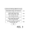
- FIG. 3 is a flowchart illustrating a code image information generating process.
- FIG. 4 shows an example of a sample original sheet.
- FIG. 5 shows an example of a code image information group.
- FIGS. 6A and 6B show a flowchart illustrating a reading control process according to the first illustrative embodiment of the present disclosures.
- FIGS. 7A and 7B show a first example of measurement result of an overlap-feeding with respect an original sheet with use of an overlap-feeding sensor.
- FIGS. 8A and 8B show a first example of measurement result of the overlap-feeding with respect original sheets with use of the overlap-feeding sensor.
- FIG. 9 is a flowchart illustrating a label detection process according to the first illustrative embodiment.
- FIGS. 10A-10C illustrate identification of a label areas with use of code image information.
- FIG. 11 is a block diagram schematically showing a configuration of an image processing system according to a second illustrative embodiment of the present disclosures.
- FIG. 12 is a flowchart illustrating a conveying process according to the second illustrative embodiment.
- FIGS. 13A and 13B show a flowchart illustrating a reading control process according to the second illustrative embodiment.
- the image processing system 1000 includes a file server 300 and a scanner 100 .
- the scanner 100 is provided with a CPU 110 serving as a controlling device to control entire operation of the scanner 100 , a volatile storage 120 such as a DRAM, a non-volatile storage 130 such as a flash memory, a display part 140 such as an LCD, an operation part 150 including operation buttons and a touch panel, an image reading part 160 configured to read an original sheet and output read image data representing an image of the original sheet, and a communication I/F 180 configured to communicate with other devices such as the file server 300 , a user's terminal device (not shown) and the like.
- a communication I/F 180 configured to communicate with other devices such as the file server 300 , a user's terminal device (not shown) and the like.
- the volatile storage 120 is used as a buffer area for temporarily storing data when the CPU 110 executes processes.
- the non-volatile storage 130 stores a computer program PG and code image information group CI.
- the computer program PG is provided, for example, as being installed in the not-volatile storage 130 during manufacturing. Alternatively, the program PG may be provided as being stored in a DVD-ROM, or may be downloaded from a server.
- the CPU 110 executes a code image information generating process and a control process of the scanner 100 including a reading control process, which processes will be described later. It is noted that the code image information group CI is generated in the code image information generating process and used in the reading control process.
- the image reading part 160 is provided with a conveyer 20 configured to convey the original sheet, an image sensor 40 configured to optically read the original sheet being conveyed, and the overlap-feeding sensor 30 .
- FIG. 2A shows a conveying passage 11 of the scanner 100 and a structure therearound.
- the conveying passage 11 is defined inside a housing 10 of the scanner 100 and are configured such that the original sheets S are conveyed therethrough.
- terms “upstream” and “downstream” are used to indicate sides along the conveying passage 11 in a conveying direction D.
- the image sensor 40 is arranged on the conveying passage 11 .
- the conveyer 20 is configured to convey multiple original sheets one by one along the conveying passage 11 , from a sheet feed tray 71 arranged on the upstream side of the conveying passage 11 to a discharge tray 72 arranged on the downstream side of the conveying passage 11 .
- an X-direction is defined to be a direction perpendicular to the conveying direction D and parallel to the original sheet S being conveyed.
- the X-direction will also be referred to as a main scanning direction.
- the conveyer 20 is a so-called ADF (abbreviation of an Automatic Document Feeder) configured to automatically convey the multiple original sheets S one by one.
- the conveyer 20 has multiple rollers which are driven by a driving force of a not-shown motor.
- the multiple rollers include, from the upstream side to the downstream side, a sheet feed roller 23 , a pair of conveying rollers 22 and a pair of discharging rollers 21 .
- the sheet feed roller 23 is arranged at the vicinity of a downstream side end portion of the sheet feed tray 71 .
- the sheet feed roller 23 in association with a separation pad 24 , picks up one of the multiple original sheets S accommodated in the sheet feed tray 71 , and feeds the picked-up original sheet S into the conveying passage 11 from the upstream side thereof.
- the discharging roller 21 is arranged on the conveying passage 11 at the vicinity of an upstream side end portion of the discharge tray 72 .
- the conveying rollers 22 are arranged along the conveying passage 11 between the discharging rollers 21 and the sheet feed roller 23 .
- the original sheet S introduced into the conveying passage 11 by the sheet feed roller 23 is further conveyed along the conveying passage 11 by the conveying rollers 22 and the discharging rollers 21 , and finally discharged onto the discharge tray 72 .
- the conveyer 20 is further provided with a front sensor 50 and a rear sensor 60 which server as an original sheet sensor to detect presence or absence of the original sheet S at a position where the front sensor 50 and the rear sensor 60 are arranged.
- the front sensor 50 is arranged on the sheet feed tray 71 at the vicinity of the sheet feed roller 23 .
- the front sensor 50 has a rotatable swingable member 52 which is swingable (rotatable) about an axis 51 extending in parallel with the X-direction.
- the rotatable swingable member 52 is located at a position as indicated in FIG. 2A .
- the rotatable swingable member 52 is displaced, with respect to the position indicated in FIG. 2A , to be slightly rotated counterclockwise.
- the front sensor 50 is configured to detect a location of the rotatable swingable member 52 , thereby detecting whether the original sheets S are present or absent at the arranged position of the front sensor 50 , or whether the original sheets S are placed on the sheet feed tray 71 .
- the rear sensor 60 is arranged on the conveying passage 11 between the conveying rollers 22 and the discharging rollers 21 , and on the upstream side relative to the image sensor 40 . Similar to the front sensor 50 , the rear sensor 60 is provided with a rotatable swingable member 62 which is swingable (rotatable) about an axis 61 extending in a direction parallel to the X-direction. When the original sheet S is not located at the position where the rear sensor 60 is arranged, the rotatable swingable member 62 is located at a position as indicated in FIG. 2A . When the original sheet S is located at the position where the rear sensor 60 is arranged, the rotatable swingable member 62 is displaced, with respect to the position indicated in FIG. 2A , to be slightly rotated clockwise. The rear sensor 60 is configured to detect a location of the rotatable swingable member 62 , thereby detecting whether the original sheet S is present or absent at the arranged position of the rear sensor 60 .
- a state where the front sensor 50 detects that the original sheet S is located at the arranged position of the front sensor 50 will also be expressed that “the sensor 50 is in an ON state” and a state where the front sensor 50 detects that the original sheet S is not located at the arranged position of the front sensor 50 will also be expressed that “the sensor 50 is in an OFF state.”
- the similar expressions will be used with respect to the states of the rear sensor 60 .
- the image sensor 5040 is a line sensor configured to read the original sheet S being conveyed by the conveyer 20 with use of a plurality of photoelectric conversion elements (e.g., CCD's or CMOS's) aligned in a line parallel to the X-direction.
- An example of such an image sensor 40 is a CIS (abbreviation of a Contact Image Sensor).
- the image sensor 40 is arranged along the conveying passage 11 , between the discharging rollers 21 and the conveying rollers 22 , and closer to the discharging rollers 21 than the conveying rollers 22 .
- the image reading part 160 generates read image data based on an output signal of the image sensor 40 on a line basis, and output the same.
- the overlap-feeding sensor 30 is for detecting the overlap-feeding state of the original sheets S.
- the overlap-feeding is a trouble that the original sheet S to be conveyed one by one is conveyed with another original sheet S being overlapped.
- the overlap-feeding sensor 30 is arranged on the upstream side relative to the conveying rollers 22 , and at the vicinity of the conveying rollers 22 .
- the overlap-feeding sensor 30 includes a transmitter 31 configured to transmit ultrasonic waves and a receiver 32 configured to receive the ultrasonic waves transmitted by the transmitter 31 .
- the receiver 32 is configured to output an electrical signal indicating an intensity of the received ultrasonic waves (i.e., a sound pressure) Wp. Based on the intensity Wp and an initial intensity of the ultrasonic waves, a damping rate DR of the ultrasonic waves can be measured.
- the transmitter 31 is arranged on a front surface side (i.e., on a side of a surface subject to be read) of the original sheet S being conveyed through the conveying passage 11 , while the receiver 32 is arranged on a rear surface side of the conveyed original sheet S.
- the ultrasonic waves transmitted by the transmitter 31 propagate through the original sheet S and received by the receiver 32 .
- the damping rate DR of the ultrasonic waves is much higher than that when the overlap-feeding state of the original sheets S is not occurring.
- the damping ratio DR of the ultrasonic waves propagating through an overlapped portion where two or more original sheets overlap becomes larger than a threshold value TH.
- the damping rate DR of the original sheet S on which a fixed object (e.g., a label) is not fixed is smaller than the threshold value TH.
- the damping rate DR of the original sheet S on which the fixed object is fixed is larger than the threshold value TH.
- a position in the X-direction subject to detection by the overlap-feeding sensor 30 is a central position, in the X-direction, of the original sheet S being conveyed, that is, a position on a detection line DL indicated by a dotted line in FIG. 2B .
- the code image information generating process is a process of generating the code image information group CI (see FIG. 1 ).
- FIG. 3 is a flowchart illustrating the code image information generating process.
- the code image information generating process is started when a start instruction of this process, which is input by the user through the operation part 150 , is obtained.
- the user may input the start instruction of the code image information generating process in a state where a sample original sheet SS is placed in the sheet feed tray 71 .
- FIG. 4 shows an example of the sample original sheet SS.
- three kinds of rectangular labels LB a, LBb and LBc are adhered on the original sheet, thereby overlapped and fixed thereon.
- the “rectangular” shape includes one of which corners are rounded to a certain degree.
- On each of the labels LBa, LBb and LBc one or more code images are indicated.
- the code image is an image expressing encoded information with use of patterns according to a particular rule.
- the code images include a one-dimensional code indicating information with alternately arranged multiple black lines and white lines (e.g., a barcode) or a two-dimensional code indicating information with tessellated pattern containing a plurality of cells (e.g., the QR code®).
- a barcode CDa is indicated on the label LBa
- a QR code CDb is indicated on the label LBb
- both a QR code CDc and a barcode CDd are indicated on the label LBc.
- Each of the barcodes and QR code indicated on the labels LBa, LBb and LBc indicates, for example, information identifying a particular commodity (e.g., a name or number of commodity).
- a particular commodity e.g., a name or number of commodity.
- N labels including N kinds of barcodes respectively corresponding to the N kinds of medicines are attached to one sheet. Then, by scanning the sheet with the scanner 100 and extracts the information corresponding to each code, management of sold medicines can be done for each customer.
- the CPU 110 controls the image reading part 160 to read the sample original sheet SS and generates sample original sheet image data, and receives the thus generated sample original sheet image data from the image reading part 160 (S 10 ).
- the CPU 11 obtains the original sheet image data and identifies code images CDa-CDd within the sample original sheet image SI indicated by the sample original sheet image.
- code images e.g., barcodes and/or QR codes
- the process of identifying the code images (e.g., barcodes and/or QR codes) within an image is a well-known process which is executed in reading devices for such code images.
- code images CDa-CDd coordinates of four apexes of each of the conde images indicated by black dots in FIG. 4 .
- the CPU 110 executes an edge extracting process on the sample original sheet image data to generates edge image data indicating edges within the sample original sheet image SI.
- the edge extracting process is, for example, a process of applying a well-known edge extracting filter (e.g., the sobel filter or the Prewitt filter) to each pixel value.
- edges indicating outer borders of each of the multiple rectangular labels LBa-LBc within the sample original sheet image SI, and edges indicating outer borders of each of the multiple code images CDa-CDd are extracted.
- the CPU 110 identifies rectangular label areas LIa-LIc respectively corresponding to the rectangular labels LBa-LBc containing code images CDa-CDd.
- the CPU 110 firstly identifies a plurality of candidate lines within the sample original sheet image SI with use of a well-known line detection algorithm (e.g., the Hough transformation or least square approximation).
- the CPU 110 then excludes outer borders and inner lines of the code images CDa-CDd from the plurality of candidate lines based on the coordinates of the four apexes of each of the code images CDa-CDd.
- the CPU 110 identifies rectangular areas each of which is defined by the remaining candidate lines and surrounds one or more images of the code images CDa-CDd.
- label areas LIa-LIc are identified as the label areas LIa-LIc.
- the label area LIa including the barcode CDa, the label area LIb including the QR code CDb, the label area LIc including the QR code CDc and the barcode CDd are identified.
- the coordinates of the four apexes of each of the plurality of label areas LIa-LIc are identified.
- the CPU 110 generates code image information for each of the identified label areas. For example, when the number of the code image included in a label area is one, the CPU 110 calculates distances between four sides of the rectangular label area and corresponding sides of the code image included in the label area, respectively. When multiple code images are included in a label area, the CPU 110 firstly identifies a circumscribed rectangle of the multiple code images, and calculates distances between the four sides of the rectangular label area and the corresponding sides of the circumscribed rectangle, respectively.
- a distance Ra between the right side of the label area LIa and the right side of the barcode CDa, a distance Ua between the upper side of the label area LIa and the upper side of the barcode CDa, a distance La between the left side of the label area LIa and the left side of the barcode CDa, and a distance Ba between the lower side of the label area LIa and the lower side of the barcode CDa are calculated.
- a distance Rb between the right side of the label area LIb and the right side of the barcode CDb, a distance Ub between the upper side of the label area LIb and the upper side of the barcode CDb, a distance Lb between the left side of the label area LIb and the left side of the barcode CDb, and a distance Bb between the lower side of the label area LIb and the lower side of the barcode CDb are calculated.
- the circumscribed rectangle CS of the QR code CDc and the barcode CDd is firstly identified. Then, a distance Rc between the right side of the label area LIc and the right side of the circumscribed rectangle CS, a distance Uc between the upper side of the label area LIc and the upper side of the circumscribed rectangle CS, a distance Lc between the left side of the label area LIc and the left side of the circumscribed rectangle CS, and a distance Bc between the lower side of the label area LIc and the lower side of the circumscribed rectangle CS are calculated.
- FIG. 5 shows an example of the code image information group CI.
- the CPU 110 generates distance data including four distances Ra, Ua, La and Ba as first code image information CIa corresponding to the label area LIa.
- the CPU 110 generates distance data including four distances Rb, Ub, Lb and Bb as second code image information CIb corresponding to the label area LIb, and distance data including four distances Rc, Uc, Lc and Bc as third code image information CIc corresponding to the label area LIc.
- the code image information group CI including the thus generated code image information CIa-CIc is stored in the non-volatile storage 130 (see FIG. 1 ).
- the code image information generating process described above by analyzing the sample image data, which is obtained by reading, with the image reading part 160 , the sample original sheet SS (see FIG. 4 ) on which particular fixed objects (e.g., the labels LBa-LBc) are fixed, the code image information CIa-CIc related to the code images CDa-CDd indicated on the labels LBa-LBc fixed on the sample original sheet SS is generated (S 20 -S 50 ). That is, with use of the sample original sheet SS, the code image information can be generated easily.
- the code image information CIa-CIc related to the code images CDa-CDd indicated on the labels LBa-LBc fixed on the sample original sheet SS is generated (S 20 -S 50 ). That is, with use of the sample original sheet SS, the code image information can be generated easily.
- the reading control process is a process, which is started based on a reading start instruction by the user, of reading M (M being an integer more than one) original sheets S placed on the sheet feed tray 71 and generating M pieces of read image data respectively representing M original sheets.
- the reading control process includes a reading process of controlling the image sensor 40 to read the original sheet S being conveyed, and a conveying process of controlling the conveyer 20 to sequentially convey the multiple original sheets S.
- the reading process and the conveying process are executed in parallel.
- FIGS. 6A and 6B show a flowchart illustrating the reading control process. It is noted, however, in the flowchart shown in FIG. 6 , only the conveying process is indicated and the reading process is not indicated for brevity.
- the CPU 110 In the reading process, when it is detected that a downstream end, in the conveying direction D, of the original sheet S has reached the position of the rear sensor 60 , the CPU 110 starts reading the original sheet S in response to the detection. Further, when it is detected that an upstream end, in the conveying direction D, of the original sheet S has reached the position of the rear sensor 60 , the CPU 110 stops reading the original sheet S. By repeating the above processes, the CPU 110 generates a plurality of pieces of read image data for the plurality of original sheets, respectively.
- the CPU 110 receives read image data based on an output signal of the image sensor 40 for each line from the image sensor 40 , and stores the same in the volatile storage 120 .
- the plurality of pieces of read image data respectively representing the plurality of original sheets S have finally been stored in the volatile storage 120 , the plurality of pieces of read image data will be stored as a single read image file (e.g., a PDF file). Then, the read image file is transmitted to a file server 300 and will be stored thereat.
- FIGS. 6A and 6B shows the reading control process and substantially showing the conveying process although the reading process is executed in parallel.
- the CPU 110 receives the reading start instruction by the user through the operation part 150 . Then, the CPU starts measurement with use of the overlap-feeding sensor 30 (S 110 ). After S 110 , the CPU 110 continuously receives the damping rate DR of the ultrasonic waves based on the output signal of the overlap-feeding sensor 30 . As will be described in detail, the CPU 110 can determine whether a portion through which the ultrasonic waves transmitted by the transmitter 31 propagate is the overlapped portion based on the damping rate DR.
- the overlapped portion is a portion of the original sheet S on which another object is overlapped.
- the overlapped portion includes a portion on which the label is overlapped with the original sheet S and fixed thereto.
- the overlapped portion also includes a portion of the original sheet S on which another original sheet S is overlapped as the overlap-feeding is occurring.
- FIGS. 7A, 7B, 8A and 8B show examples of measurement results by the overlap-feeding sensor 30 with respect to the original sheet S.
- three labels LBe, LBf and LBg are overlapped with the original sheet S and fixed thereto.
- the detection position of the overlap-feeding sensor 30 is a portion on a one-dotted line DL shown in FIG. 7A and measurement by the overlap-feeding sensor 30 starts from the downstream end (i.e., an upper end in FIG. 7 ) and moves toward the upstream end (i.e., a lower end in FIG. 7 ) as the original sheet S 1 is conveyed in the conveying direction D.
- FIG. 7B shows the damping rate DR measured by the overlap-feeding sensor 30 .
- the CPU 110 determines whether a length, in the conveying direction D, of the portion of which damping rate DR is equal to or larger than the threshold value TH exceeds the reference length Lth. In the example shown in FIGS. 7A and 7B , when the position, in the conveying direction D, of the detecting portion has reached a position P 1 , the damping rate DR exceeds the threshold value TH.
- the position of the detecting portion in the conveying direction D has reached a position P 2 , which is on the upstream side from the position P 1 by the reference length Lth, with the damping rate DR being kept exceeding the threshold value TH, it is determined that the length, in the conveying direction D, of the portion of which damping rate is equal to or larger than the threshold value TH exceeds the reference length Lth. That is, when the length, in the conveying direction D, of the portion exhibiting the damping rate DR equal to or larger than the threshold value TH exceeds the reference length Lth, the currently detected portion is determined to be the overlapped portion.
- Whether the detecting position has been moved from the position P 1 to the position P 2 can be determined by determining whether the conveyed amount of the original sheet S after the detecting position has reached the position P 1 (i.e., when the damping rate DR has exceeded the threshold value TH) has reached the reference length Lth based on, for example, a rotation amount of the conveying roller 22 .
- the detecting portion subject to detection by the overlap-feeding sensor 30 at the point of time when the length of the overlapped portion in the conveying direction D has exceeded the reference length Lth, that is, the portion determined to be the overlapped portion will also be referred to as an interested detection position.
- the CPU 110 obtains partial image data indicating a partial image including the interested detection position (e.g., the position P 2 ). For example, the CPU 110 pauses until reading by the image sensor 40 proceeds and partial image data representing a partial image which includes the interested detection position (e.g., position P 2 ) and having a particular width B 1 is stored in the volatile storage 120 .
- the particular width B 1 is set to be sufficiently wide so that, when a label image exists within the interested detection position, the entire label image is included within the partial image.
- the CPU 110 identifies the code image (e.g., the barcode or the QR code) within the partial image represented by the partial image data which has been obtained. Identification of the codes is performed in accordance with a well-known method as in S 320 of FIG. 3 . As a result of the identification, according to the example shown in FIGS. 7A and 7B , coordinates of four apexes (indicated by black dots) of a rectangular barcode CDa CDe and an inclination ⁇ are identified.
- the code image e.g., the barcode or the QR code
- the CPU 110 determines whether a code image is identified within the partial image. When no code image is identified within the partial image (S 130 : NO), it is considered that the overlap-feeding is occurring. In such a case, since it is considered that the label is not overlapped with the original sheet S and fixed thereto at the interested detection position, the reason why the interested detection position is determined to be the overlapped portion is not a label is being overlapped with the original sheet S. Therefore, it is determined that the determination of the overlap-feeding at the interested detection position is made since the overlap-feeding of the original sheets S is actually occurring.
- the CPU 110 stops driving the discharging rollers 21 , the conveying rollers 22 , and the sheet feed roller 23 to interrupt conveying of the original sheets S (S 145 ). Further, in S 150 , the CPU 110 notifies the user of occurrence of the overlap-feeding of the original sheets S. For example, the CPU 110 displays a notification screen indicating a message notifying that the overlap-feeding is occurring and page numbers of the original sheets S which are conveyed in an overlapped manner on the display part 140 . After execution of S 150 , the conveying process is abended. According to the embodiment, the reading process which is executed in parallel with the conveying process is also abended. That is, the reading control process is abended.
- the label detection process is a process of determining whether there exists a label including a code image (e.g., the barcode or the QR code) at the interested detection position by analyzing at least a part of the read image data.
- a code image e.g., the barcode or the QR code
- the CPU 110 determines whether it is determined that the label exists at the interested detection position as a result of the label detection process. When it is determined that there exists a label at the interested detection position (S 140 : YES), it is considered that the overlap-feeding of the original sheets S is not occurring. In such a case, since the label is overlapped and fixed at the interested detection position, it is determined that the interested detection position is the overlapped position as the label is overlapped with the original sheet S at the interested detection position. Therefore, in this case, the CPU 110 proceeds to S 155 without executing process in S 145 or S 150 .
- the CPU 110 determines whether conveyance of one original sheet S has been completed.
- the state of the rear sensor 60 is changed from the ON state, which indicates that the original sheet S exists at the arrangement position of the rear sensor 60 , to the OFF state, which indicates that the original sheet S does not exist at the arrangement position of the rear sensor 60 , and thereafter, the original sheet S is further conveyed by a particular amount, it is considered that the original sheet S has been discharged onto the discharge tray 72 . In such a case, it is determined that conveyance of the original sheet S has been completed.
- the CPU 110 determines whether there exists an unconveyed original sheet S in the sheet feed tray 71 (S 160 ).
- the CPU 110 determines whether there exists an unconveyed original sheet S in the sheet feed tray 71 (S 160 ).
- the front processor 50 is in the ON state, which indicates that there exists an original sheet S in the sheet feed tray 71 , it is determined that there exists a unconveyed original sheet S in the sheet feed tray 71 .
- the CPU 110 returns to S 115 and starts conveying the next original sheet S.
- the CPU 111 terminates the conveying process (i.e., the reading control process).
- FIG. 9 is a flowchart illustrating the label detection process which is a subroutine called in S 135 of FIG. 6B .
- the CPU 110 calculates the length L 1 , in the conveying direction D, of each of the fixed objects based on the detection results of the overlap-feeding sensor 30 .
- the CPU 110 calculates the conveying amount of the original sheet S based on the rotation amount of the conveying rollers 22 from a point of time when the damping rate DR exceeds the threshold value TH until the damping rate DR falls below the threshold value TH. Then, the calculated conveying amount is regarded as the length L 1 of the fixed object in the conveying direction D.
- the detection position when it is determined that the length of the overlapped portion in the conveying direction D exceeds the threshold value TH in S 120 is a position, in the conveying direction D, where the label LBe is located, the length L 1 e shown in FIG. 7 is calculated as the length L 1 of the fixed object in the conveying direction D.
- the CPU 110 obtains one piece of interested code image information from among the code image information CIa-CIc ( FIG. 5 ) included in the code image information group having been stored in the non-volatile storage 130 .
- FIG. 210 the CPU 110 determines a label area with use of the interested code image information. As a result of identification of the label area, coordinates of the four apexes of the determined label area are calculated.
- FIGS. 10A-10C illustrate identification of the label areas with use of the code image information. In the examples of FIGS. 10A-10C , it is assumed that the code image having been identified in S 125 of FIG. 6B is a barcode CDe in FIG. 7 .
- the label area determined to include the barcode CDe is a label area IAa shown in FIG. 10A .
- the label area IAa is configured such that four sides thereof are parallel to the corresponding four sides of the barcode CDe, respectively, and distances between the four sides of the label area IAa and the corresponding four sides of the barcode CDe are distances Ua, Ra, Ba and La included in the first code image information CIa.
- the label area determined to include the barcode CDe is a label area IAb shown in FIG. 10B .
- the label area IAb is configured such that four sides thereof are parallel to the corresponding four sides of the barcode CDe, respectively, and distances between the four sides of the label area IAb and the corresponding four sides of the barcode CDe are distances Ub, Rb, Bb and Lb included in the second code image information CIa.
- the label area determined to include the barcode CDe is a label area IAc shown in FIG. 10C .
- the label area IAc is configured such that four sides thereof are parallel to the corresponding four sides of the barcode CDe, respectively, and distances between the four sides of the label area IAc and the corresponding four sides of the barcode CDe are distances Uc, Rc, Bc and Lc included in the third code image information CIa.
- the coordinates of the four apexes of the barcode CDe within the label area IAb will be referred to as (x1, y1), (x2, y2), (x3, y3) and (x4, y4), respectively, as indicated in FIG. 10B , and an inclination of the barcode CDe relative to the conveying direction D will be referred to as 0 .
- coordinates (cx1, cy1), (cx2, cy2), (cx3, cy3) and (cx4, cy4) of the four apexes of the label area IAb to be calculated are expressed with use of following equations (1)-(8).
- cx 1 x 1 +Ub *sin ⁇ Lb *cos ⁇ (1)
- cy 1 y 1 +Ub *cos ⁇ + Lb *sin ⁇ (2)
- cx 2 x 2 +Ub *sin ⁇ + Rb *cos ⁇ (3)
- cy 2 y 2 +Ub *cos ⁇ Rb *sin ⁇ (4)
- cx 3 x 3 ⁇ Lb *cos ⁇ Bb *sin ⁇ (5)
- cy 3 y 3 +Lb *sin ⁇ Bb *cos ⁇ (6)
- cx 4 x 4 ⁇ Bb *sin ⁇ + Rb *cos ⁇ (7)
- cy 4 y 4 ⁇ Bb *cos ⁇ Rb *sin ⁇ (8)
- the four apexes of the code image e.g., the barcode CDe
- the distances e.g., Rb, Ub, Lb and Bb
- the label area can be identified with a high precision, and accordingly, whether the label exists at the interested detection position can be determined with a high precision in S 215 -S 240 .
- the label area LIe corresponding to the label LBe including the barcode CDe is a label corresponding to the first code image information CIa
- distances between the four sides of the barcode CDe and corresponding four sides of the label area LIe coincide with the distances Ua, Ra, Ba and La included in the first code image information CIa.
- the label area LIe does not correspond to the second code image information CIb or the third code image information CIc.
- a label area LIe ( FIG. 7A ) to be actually identified on the original sheet S 1 coincides with the label area IAa (see FIG. 10A ) which is identified with use of the first code image information CIa, but does not coincide with a label area IAb ( FIG. 10B ) or LAc ( FIG. 10C ) which are identified with use of the second code image information CIb or the third code image information CIc, respectively.
- two sides intersecting with the detection line DL of the overlap-feeding sensor are identified. Identification of the two sides are performed based on the position in the X direction (i.e., the direction perpendicular to the conveying direction D) at which the detection position (i.e., the detection line DL) is positioned. For example, when it is assumed that the label area IAa ( FIG. 10A ) is the identified label area and the line DL 1 ( FIG. 10A ) is the detection line LD, a left side SDL and a lower side SDB are identified. When it is assumed that the label area IAa ( FIG. 10A ) is the identified label area and the line DL 2 ( FIG.
- the detection line DL is a phantom line which passes the detection position and extends in parallel with the conveying direction D.
- the CPU 110 calculates a distance L 2 between two intersecting points at which the identified two sides intersect with the detection line DL.
- the length L 2 of the two intersecting points is, in other words, a length L 2 of the fixed objects based on analysis of the image with use of the code image information CIa-CIc in S 205 -S 220 .
- a length (i.e., a distance) L 21 between the two intersecting points d 1 and d 2 is identified.
- 10A is the identified label area and the line DL 2 is the detection line DL, a length (i.e., a distance) L 22 between the two intersecting points d 3 and d 4 is identified.
- a length (i.e., a distance) L 23 between the two intersecting points d 5 and d 6 is identified.
- the length L 1 and the length L 2 are considered to be substantially the same. Therefore, when the length L 1 and the length L 2 are substantially the same (S 225 : YES), the CPU 110 determines that there exists a label at the interested detection position in S 240 .
- the CPU 110 determines whether the CPU 110 has processed all the pieces of code image information included in the code image information group CI as the interested code image information. When there remains unprocessed code image information (S 230 : NO), the CPU 110 returns to S 205 and obtains the unprocessed code image information as the interested code image information.
- the detection position of the original sheet being conveyed is in the overlap-feeding state (S 120 ). Then, partial image data indicative of a partial image included the image at the interested detection position or the original sheet S is obtained ( FIG. 6B , S 122 ). By analyzing the partial image data with use of the code image information CIa-CIc, it is determined whether there exists a label including the code image at the interested detection position (S 125 -S 136 and FIG. 9 ).
- the length L 1 of the fixed object which is calculated in S 200 based on the detection result of the overlap-feeding sensor 30 is represented as L 1 e, L 1 f and L 1 g for the label areas LIe, LIf and LIg corresponding to the labels LBe, LBf and LBg, respectively.
- the length L 2 of the fixed object which is calculated in S 205 -S 220 based on the image analysis is represented as L 2 e, L 2 f and L 2 g for the label areas LIe, LIf and LIg, respectively. Further, the above lengths satisfy conditions below. L1e ⁇ L2e; L1f ⁇ L2f; and L1g ⁇ L2g.
- the overlap-feeding is occurring. That is, the length L 1 is represented as L 1 e in an upper label area LIe, while L 1 h in an area where a lower label area LIf, the original sheet S 1 and the original sheet S 2 overlap.
- the length L 2 of the fixed object which is calculated in S 205 -S 220 based on the image analysis is represented as L 2 e, and represented as L 2 f for a label area LIf. It is noted that L 1 e ⁇ L 2 e, but L 1 h ⁇ L 2 f.
- the partial image data representing a part of the original sheet S, but not the entire image data is analyzed in S 125 -S 135 and FIG. 9 . Therefore, in comparison with a case where, for example, all the data accumulated from the start of reading is analyzed, load for data analysis can be reduced.
- the code image information CIa-Cic include distances (e.g., Ra, Ua, La and Ba) which are information indicating positions at which the barcodes and QR codes are arranged relative to the labels LBa, LBb and LBc (see FIGS. 4 and 5 ).
- the CPU 110 is configured to identify the code images within an image indicating the original sheet S 1 (S 130 ), and identify the label areas within the image based on the positions of the code images within the image and distances (i.e., position information) (S 135 , S 210 ).
- the CPU 110 determines whether a label exists at the interested detection position based on the identifying results of the labels (S 215 -S 240 ).
- the position information indicating positions at which the code images are arranged relative to the label areas whether the label exists at the interested detection position can be determined with a high precision.
- the CPU 110 interrupts conveyance of the original sheet S, and when it is determined that one of the labels LBa-LBc exits at the interested detection position, the CPU 110 continues conveyance of the original sheet S (S 205 -S 240 ). Therefore, it is possible to suppress a defect such that conveyance of the original sheet S is interrupted in response to one of the labels LBa-Lbc being fixed to the original sheet S although the overlap-feeding of the original sheets S is not occurring.
- the image reading part 160 is an example of a reading execution part and the CPU 110 and the volatile storage 120 constitute an example of a controlling device.
- FIG. 11 is a block diagram showing an image processing system 1000 B according to a second embodiment of the present disclosures.
- the image processing system 1000 B includes a scanner 100 B and a terminal device 200 B which is communicatably connected to the scanner 100 B through a network NT.
- the scanner 100 B is different from the scanner 100 according to the first embodiment in terms of a structure of the non-volatile storage 130 B.
- a computer program PG 1 which is different from the computer program PG shown in FIG. 1 is stored.
- the code image information group CI is not stored.
- the configurations other than the above are the same as those of the scanner 100 according to the first embodiment as shown in FIGS. 1, 2A and 2B .
- elements same as those of the scanner 100 according to the first embodiment are assigned with the same reference numbers.
- the CPU 110 executes a scanner side reading control process which will be described later.
- the terminal device 200 B is a well-known computer such as a personal computer.
- the terminal device 200 B is provided with a CPU 210 serving as a controlling device for controlling the terminal device 200 B entirely, a volatile memory 220 such as a DRAM, a non-volatile storage 230 such as a hard disk, a display part 240 such as an LCD, an operating part 250 such a mouth and a keyboard, and a communication I/F 280 used for communicating with another device (e.g., scanner 100 B).
- a CPU 210 serving as a controlling device for controlling the terminal device 200 B entirely
- a volatile memory 220 such as a DRAM
- a non-volatile storage 230 such as a hard disk
- a display part 240 such as an LCD
- an operating part 250 such a mouth and a keyboard
- a communication I/F 280 used for communicating with another device (e.g., scanner 100 B).
- the volatile storage 220 is used as a buffer area for temporarily storing data when the CPU 210 executes processes.
- the computer program PG 2 and the code image information group CI ( FIG. 5 ) are stored.
- the computer program PG 2 is provided such that it is downloaded from a server.
- the computer program PG 2 may be provided such that it is installed in the non-volatile storage 130 at a time of manufacturing, or may be stored in the DVD-ROM or the like.
- the CPU 110 executes a terminal side reading control process, the conde image information group CI is used in the reading control process.
- the scanner 100 B and the terminal device 200 B are associated with each other to execute the reading control process which is the same as the reading control process execute by the scanner 100 according to the first embodiment.
- the reading control process executed by the scanner 100 B includes a reading process of controlling the image sensor 40 to read the original sheet S being conveyed, and a conveying process of controlling the conveyer 20 to convey the multiple original sheets S sequentially (i.e., one by one).
- the reading process and the conveying process are executed in parallel.
- the reading process in response to detection that the downstream end, in the conveying direction D, of the original sheet S has reached the position of the rear sensor 60 , the CPU 110 starts reading the original sheet S, and in response to detection that the upstream end, in the conveying direction D, of the original sheet S has reached the position of the rear sensor 40 , the CPU 110 stops reading the original sheet S.
- the CPU 110 reads the original sheets S one by one.
- the CPU 110 obtains read image data based on the output signal of the image sensor on a line basis from the image sensor 40 , and stores the obtained read image data in the volatile storage 120 .
- the read image data stored in the volatile storage 120 is transmitted to the terminal device 200 B together with the damping rate DR in S 345 of a conveying process which is described later.
- FIG. 12 is flowchart illustrating the conveying process according to the second embodiment.
- the CPU 110 receives the start command, which is transmitted from the terminal device 200 .
- the CPU 110 starts measuring with use of the overlap-feed sensor 30 . Thereafter, the CPU 110 continuously obtains the damping rate DR of the ultrasonic waves base on the output signal of the overlap-feeding sensor 30 .
- the CPU 110 determines whether an overlap-feeding notification from the terminal device 200 B is received. When it is determined that the overlap-feeding is received (S 320 : YES), the CPU 110 stops driving of rollers 21 , 22 and 23 to stop feeding of the original sheet S, as in S 145 of FIG. 6B . Further, in S 350 , the CPU 110 notifies a user of occurrence of the overlap-feeding, as in S 150 of FIG. 6B . After execution of S 150 S 350 , the conveying process is abended. In such a case, the reading process which is being executed in parallel with the conveying process is also abended.
- the CPU 110 transmits the above-described read image data temporarily stored in the volatile storage 120 , the damping rate DR and the page information to the terminal device 200 B in a synchronized manner, on a line basis.
- the read image data and the damping rate DR are not synchronized with each other and the damping rate is obtained at a delayed timing.
- the read image data and the damping rate DR are synchronized, and then transferred to the terminal device 200 B.
- the CPU 110 determines whether conveyance of one original sheet S has been completed, as is S 155 of FIG. 6B . When it is determined that conveyance of one original sheet S has not been completed (S 360 : NO), the CPU 110 returns to S 320 . When it is determined that conveyance of one original sheet S has been completed (S 360 : YES), the CPU 110 transmits a one-sheet completion notification indicating that conveyance of one original sheet S has been completed to the terminal device 200 B in S 365 . In S 370 , the CPU 110 determines whether there remains an unconveyed original sheet S in the sheet feed tray 71 as in S 160 of FIG. 6A .
- the CPU 110 When it is determined that there remains an unconveyed original sheet S in the sheet feed tray 71 (S 370 : YES), the CPU 110 returns to S 315 and starts conveying the next one original sheet S. When it is determined that there remains no original sheet S in the sheet feed tray 71 (S 370 : NO), the CPU 110 transmits all-sheet completion notification indicating completion of conveyance of all the original sheets S to the terminal device 200 B and terminates the conveying process.
- the reading control process of the terminal device 200 B is a process of receiving the image reading data, the damping rate DR and the page information from the scanner 100 B, and generating a read image file.
- the reading control process of the terminal device 200 B includes a process of notifying the scanner 100 B of occurrence of the overlap-feeding of the original sheets S.
- FIGS. 13A and 13B show a flowchart illustrating the reading control process of the terminal device 200 B.
- the CPU 210 of the terminal device 200 B receives the reading start instruction by the user through the operation part 250 .
- the CPU 210 transmits the start command to the scanner 100 B.
- the conveying process in the scanner 100 B (described above) is started.
- the CPU 210 starts receiving the read image data, the damping rate DR and the page information from the scanner 100 B. Such information is transmitted by the scanner 100 B in S 355 of FIG. 12 .
- the read image data, the damping rate DR and the page information are stored in the volatile storage 220 .
- Processes in S 422 -S 440 are the same as those in S 122 -S 140 in FIG. 6B , and description thereof will be omitted for brevity.
- the CPU 110210 determines whether one-sheet completion notification is received. When the one-sheet completion notification has not been received (S 455 : NO), the CPU 210 returns to S 420 . When the one-sheet completion notification has been received (S 455 : YES), the CPU 210 determines whether the all-sheet completion notification has been received in S 460 . When the all-sheet completion notification has not been received (S 460 : NO), the CPU 210 returns to S 420 . When the all-sheet completion notification has been received (S 460 : YES), the read image data indicating all the original sheets S have been received by that timing. The CPU 210 generates one original sheet image data (e.g., a PDF file) with use of the read image data, the CPU 210 terminates the reading control process of the terminal device 200 B.
- one original sheet image data e.g., a PDF file
- the terminal device 200 B and the scanner 100 B cooperate in association with each other to execute the reading control process substantially the same as that in the first embodiment.
- the effects same as that of the first embodiment can be obtained.
- the scanner 100 B according to the present embodiment is an example of a scanner and a reading execution part.
- the overlap-feeding notification according to the present embodiment is an example of an interruption command
- the terminal device 200 B according to the present embodiment is an example of an image processing device.
- the overlap-feeding sensor 30 detects the damping rate DR of the ultrasonic waves passing propagating through the original sheets being conveyed.
- a sensor configured to detect transmittance of light passing through the original sheets being conveyed may be employed.
- a micro-displacement sensor configured to measure a thickness of the original sheets being conveyed may be employed.
- various sensors capable of detecting information on physical characteristics of the original sheets S being conveyed can be used.
- labels are used as particular fixed objects which are fixed on the original sheet S in an overlapped manner
- an IC tag, a seal, a tape, a piece of cloth may be used as the fixed object.
- a code image such as a barcode or a QR code is employed as a particular image indicated on the particular fixed object.
- a particular character(s)/letter(s) or an image of a particular mark or symbol may be used.
- the particular image information information indicating distanced between the four sides of the code image, which is the particular image, and the corresponding four sides of the label are used.
- the particular image information may be information indicating the type, size and the number of letters. Further, the information may be one indicating different shapes and sizes of the fixed object depending on the kinds and/or numbers of the letters.
- information regarding the particular image that is, information for identifying a particular image, or information for identifying a fixed object including the particular image may be used.
- the label is assumed to be a rectangle.
- the label may have a different shape (e.g., a circle).
- the code image information may be information indicating an arrangement position of the code image within a circular label.
- the code image information group CI includes three pieces of code image information CIa-CIc.
- the number of code image information may be an arbitrary number (e.g., one, two or five).
- whether or not a label exists is determined based on one or a plurality of pieces of code image information, designated by a user, from among the plurality of pieces of the code image information CI, and not based on the code image information not designated by the user.
- the code image information group CI is generated by analyzing the image data of the sample original sheet which is obtained by reading the sample original sheet SS ( FIG. 3 ).
- the code image information group CI may be generated based on the four distances (e.g., Ua, La, Ra and Ba) input by the user through a particular UI screen.
- a part of a configuration realized by a hardware may be replaced with a software.
- a part of or the all of a configuration realized by a software may be replaced with hardware(s).
- a part of or all of the processed of the reading process in each of the embodiments described above may be replaced with a hardware such as an ASIC.
Landscapes
- Engineering & Computer Science (AREA)
- Multimedia (AREA)
- Signal Processing (AREA)
- Facsimiles In General (AREA)
- Facsimile Scanning Arrangements (AREA)
- Image Input (AREA)
Abstract
Description
cx1=x1+Ub*sinθ−Lb*cos θ (1)
cy1=y1+Ub*cos θ+Lb*sin θ (2)
cx2=x2+Ub*sin θ+Rb*cos θ (3)
cy2=y2+Ub*cos θ−Rb*sin θ (4)
cx3=x3−Lb*cos θ−Bb*sin θ (5)
cy3=y3+Lb*sin θ−Bb*cos θ (6)
cx4=x4−Bb*sin θ+Rb*cos θ (7)
cy4=y4−Bb*cos θ−Rb*sin θ (8)
L1e≈L2e;
L1f≈L2f; and
L1g≈L2g.
Claims (16)
Applications Claiming Priority (2)
| Application Number | Priority Date | Filing Date | Title |
|---|---|---|---|
| JP2017-222956 | 2017-11-20 | ||
| JP2017222956A JP6982275B2 (en) | 2017-11-20 | 2017-11-20 | Control device and computer program |
Publications (2)
| Publication Number | Publication Date |
|---|---|
| US20190158692A1 US20190158692A1 (en) | 2019-05-23 |
| US10432810B2 true US10432810B2 (en) | 2019-10-01 |
Family
ID=66533502
Family Applications (1)
| Application Number | Title | Priority Date | Filing Date |
|---|---|---|---|
| US16/192,869 Active US10432810B2 (en) | 2017-11-20 | 2018-11-16 | Scanner and non-transitory computer-readable recording medium for image processing device |
Country Status (2)
| Country | Link |
|---|---|
| US (1) | US10432810B2 (en) |
| JP (1) | JP6982275B2 (en) |
Cited By (2)
| Publication number | Priority date | Publication date | Assignee | Title |
|---|---|---|---|---|
| US10674026B1 (en) * | 2019-06-27 | 2020-06-02 | Kyocera Document Solutions Inc. | Total information digitalization from detachable-note-adhered documents |
| US20210155430A1 (en) * | 2019-11-27 | 2021-05-27 | Canon Kabushiki Kaisha | Sheet conveying apparatus and image reading apparatus |
Families Citing this family (1)
| Publication number | Priority date | Publication date | Assignee | Title |
|---|---|---|---|---|
| US11057531B2 (en) * | 2019-01-03 | 2021-07-06 | Kodak Alaris Inc. | Operating an appliance scanner system |
Citations (7)
| Publication number | Priority date | Publication date | Assignee | Title |
|---|---|---|---|---|
| JPH07291485A (en) | 1994-04-28 | 1995-11-07 | Ricoh Co Ltd | Double-feed detection device and document feeder equipped with the same |
| US20080036139A1 (en) * | 2006-08-14 | 2008-02-14 | Gregory Reyner | Non-contact sensing system |
| US20090085284A1 (en) | 2007-10-01 | 2009-04-02 | Fuji Xerox Co., Ltd. | Overlapped conveyance detection apparatus for printing sheet |
| US7526969B2 (en) * | 2004-01-07 | 2009-05-05 | Pepper1 + Fuchs Gmbh | Method and device for the contactless detection of flat objects |
| JP2009256073A (en) | 2008-04-18 | 2009-11-05 | Canon Electronics Inc | Double feed detecting device and double feed detection method |
| US8413981B2 (en) * | 2009-02-26 | 2013-04-09 | Brother Kogyo Kabushiki Kaisha | Sheet bundle with storage tags, method of manufacturing the same, and sheet transport mechanism in image forming apparatus |
| US9796547B2 (en) * | 2016-01-29 | 2017-10-24 | Riso Kagaku Corporation | Conveyance control device |
Family Cites Families (2)
| Publication number | Priority date | Publication date | Assignee | Title |
|---|---|---|---|---|
| JP2010124423A (en) * | 2008-11-21 | 2010-06-03 | Canon Electronics Inc | Image reading apparatus, image reading system and method of controlling the same |
| JP5451519B2 (en) * | 2010-05-14 | 2014-03-26 | 株式会社Pfu | Image reading apparatus, multifeed determination method, and multifeed determination program |
-
2017
- 2017-11-20 JP JP2017222956A patent/JP6982275B2/en active Active
-
2018
- 2018-11-16 US US16/192,869 patent/US10432810B2/en active Active
Patent Citations (8)
| Publication number | Priority date | Publication date | Assignee | Title |
|---|---|---|---|---|
| JPH07291485A (en) | 1994-04-28 | 1995-11-07 | Ricoh Co Ltd | Double-feed detection device and document feeder equipped with the same |
| US7526969B2 (en) * | 2004-01-07 | 2009-05-05 | Pepper1 + Fuchs Gmbh | Method and device for the contactless detection of flat objects |
| US20080036139A1 (en) * | 2006-08-14 | 2008-02-14 | Gregory Reyner | Non-contact sensing system |
| US20090085284A1 (en) | 2007-10-01 | 2009-04-02 | Fuji Xerox Co., Ltd. | Overlapped conveyance detection apparatus for printing sheet |
| JP2009084003A (en) | 2007-10-01 | 2009-04-23 | Fuji Xerox Co Ltd | Double feed detection apparatus for paper sheet |
| JP2009256073A (en) | 2008-04-18 | 2009-11-05 | Canon Electronics Inc | Double feed detecting device and double feed detection method |
| US8413981B2 (en) * | 2009-02-26 | 2013-04-09 | Brother Kogyo Kabushiki Kaisha | Sheet bundle with storage tags, method of manufacturing the same, and sheet transport mechanism in image forming apparatus |
| US9796547B2 (en) * | 2016-01-29 | 2017-10-24 | Riso Kagaku Corporation | Conveyance control device |
Non-Patent Citations (1)
| Title |
|---|
| User's manual of "DR-XIOC"(Canon), pp. 8-17, issued in 2007, with English translation. |
Cited By (5)
| Publication number | Priority date | Publication date | Assignee | Title |
|---|---|---|---|---|
| US10674026B1 (en) * | 2019-06-27 | 2020-06-02 | Kyocera Document Solutions Inc. | Total information digitalization from detachable-note-adhered documents |
| US20210155430A1 (en) * | 2019-11-27 | 2021-05-27 | Canon Kabushiki Kaisha | Sheet conveying apparatus and image reading apparatus |
| US11807490B2 (en) * | 2019-11-27 | 2023-11-07 | Canon Kabushiki Kaisha | Sheet conveying apparatus and image reading apparatus |
| US20240025684A1 (en) * | 2019-11-27 | 2024-01-25 | Canon Kabushiki Kaisha | Sheet conveying apparatus and image reading apparatus |
| US12319537B2 (en) * | 2019-11-27 | 2025-06-03 | Canon Kabushiki Kaisha | Sheet conveying apparatus and image reading apparatus |
Also Published As
| Publication number | Publication date |
|---|---|
| US20190158692A1 (en) | 2019-05-23 |
| JP6982275B2 (en) | 2021-12-17 |
| JP2019096968A (en) | 2019-06-20 |
Similar Documents
| Publication | Publication Date | Title |
|---|---|---|
| US10432810B2 (en) | Scanner and non-transitory computer-readable recording medium for image processing device | |
| JP7047318B2 (en) | Transfer device, program and control method of transfer device | |
| US20150009520A1 (en) | Tilt angle correction apparatus, image reader, image forming apparatus, and non-transitory computer readable medium storing program | |
| US9143653B2 (en) | Image processing apparatus, method, and computer program product identifying show-through position based on back side image and expanded front side image | |
| CN110516494A (en) | A kind of two-dimensional code identification method, device, equipment and system | |
| JP5683099B2 (en) | Image reading apparatus, image reading apparatus control method, and program | |
| KR102794647B1 (en) | Code reading device, program recording medium, code reading system and code reading method | |
| US20130094065A1 (en) | Determining document characteristics prior to scanning | |
| US8885185B2 (en) | Image forming system, controller and rasterization accelerator | |
| US9036222B2 (en) | Document scanner | |
| US20240323290A1 (en) | Image processing system, non-transitory computer readable medium, and method for processing image | |
| US11399108B2 (en) | Image reading apparatus capable of determining whether missing part of document image occurs based on edge shape of at least one of leading and trailing edges of document image | |
| JP2006082386A (en) | Printing system | |
| US12081710B2 (en) | Image reading device and image reading method | |
| JP6905393B2 (en) | Image reader | |
| JP2005150837A (en) | Document processor | |
| JP2005348376A (en) | Image reading device | |
| JP2020024111A (en) | Inspection device and inspection method | |
| US12321812B1 (en) | Methods and systems for light based accidental scan avoidance | |
| JP2020024110A (en) | Inspection device and inspection method | |
| US11388308B2 (en) | Creating label form templates | |
| US20240214499A1 (en) | Image reading device and image reading method | |
| JP2007086936A (en) | Method and device for detecting two-dimensional bar code | |
| JP7510602B2 (en) | Image reader | |
| JP7510603B2 (en) | Image reader |
Legal Events
| Date | Code | Title | Description |
|---|---|---|---|
| AS | Assignment |
Owner name: BROTHER KOGYO KABUSHIKI KAISHA, JAPAN Free format text: ASSIGNMENT OF ASSIGNORS INTEREST;ASSIGNOR:FUJIWARA, SHINGO;REEL/FRAME:047521/0194 Effective date: 20181113 |
|
| FEPP | Fee payment procedure |
Free format text: ENTITY STATUS SET TO UNDISCOUNTED (ORIGINAL EVENT CODE: BIG.); ENTITY STATUS OF PATENT OWNER: LARGE ENTITY |
|
| STPP | Information on status: patent application and granting procedure in general |
Free format text: NOTICE OF ALLOWANCE MAILED -- APPLICATION RECEIVED IN OFFICE OF PUBLICATIONS |
|
| STPP | Information on status: patent application and granting procedure in general |
Free format text: PUBLICATIONS -- ISSUE FEE PAYMENT VERIFIED |
|
| STCF | Information on status: patent grant |
Free format text: PATENTED CASE |
|
| MAFP | Maintenance fee payment |
Free format text: PAYMENT OF MAINTENANCE FEE, 4TH YEAR, LARGE ENTITY (ORIGINAL EVENT CODE: M1551); ENTITY STATUS OF PATENT OWNER: LARGE ENTITY Year of fee payment: 4 |