US10427954B2 - Method and apparatus for liquid disinfection using light transparent conduit - Google Patents
Method and apparatus for liquid disinfection using light transparent conduit Download PDFInfo
- Publication number
- US10427954B2 US10427954B2 US15/137,191 US201615137191A US10427954B2 US 10427954 B2 US10427954 B2 US 10427954B2 US 201615137191 A US201615137191 A US 201615137191A US 10427954 B2 US10427954 B2 US 10427954B2
- Authority
- US
- United States
- Prior art keywords
- conduit
- liquid
- sleeve
- light
- transparent
- Prior art date
- Legal status (The legal status is an assumption and is not a legal conclusion. Google has not performed a legal analysis and makes no representation as to the accuracy of the status listed.)
- Active
Links
- 239000007788 liquid Substances 0.000 title claims abstract description 69
- 238000004659 sterilization and disinfection Methods 0.000 title claims abstract description 42
- 238000000034 method Methods 0.000 title description 13
- 239000011248 coating agent Substances 0.000 claims description 22
- 238000000576 coating method Methods 0.000 claims description 22
- 239000010453 quartz Substances 0.000 claims description 9
- VYPSYNLAJGMNEJ-UHFFFAOYSA-N silicon dioxide Inorganic materials O=[Si]=O VYPSYNLAJGMNEJ-UHFFFAOYSA-N 0.000 claims description 9
- 238000005286 illumination Methods 0.000 abstract description 4
- 238000009826 distribution Methods 0.000 description 22
- 230000004907 flux Effects 0.000 description 10
- 230000008569 process Effects 0.000 description 9
- 229910001220 stainless steel Inorganic materials 0.000 description 8
- 239000010935 stainless steel Substances 0.000 description 8
- 229910052751 metal Inorganic materials 0.000 description 7
- 239000002184 metal Substances 0.000 description 7
- 238000005094 computer simulation Methods 0.000 description 6
- 239000011521 glass Substances 0.000 description 5
- 239000000463 material Substances 0.000 description 4
- 238000004088 simulation Methods 0.000 description 4
- 229920006362 Teflon® Polymers 0.000 description 3
- 230000000694 effects Effects 0.000 description 3
- XLYOFNOQVPJJNP-UHFFFAOYSA-N water Substances O XLYOFNOQVPJJNP-UHFFFAOYSA-N 0.000 description 3
- MHAJPDPJQMAIIY-UHFFFAOYSA-N Hydrogen peroxide Chemical compound OO MHAJPDPJQMAIIY-UHFFFAOYSA-N 0.000 description 2
- GWEVSGVZZGPLCZ-UHFFFAOYSA-N Titan oxide Chemical compound O=[Ti]=O GWEVSGVZZGPLCZ-UHFFFAOYSA-N 0.000 description 2
- 229910052782 aluminium Inorganic materials 0.000 description 2
- XAGFODPZIPBFFR-UHFFFAOYSA-N aluminium Chemical compound [Al] XAGFODPZIPBFFR-UHFFFAOYSA-N 0.000 description 2
- 230000008901 benefit Effects 0.000 description 2
- 230000000052 comparative effect Effects 0.000 description 2
- 230000008021 deposition Effects 0.000 description 2
- 230000007246 mechanism Effects 0.000 description 2
- 230000004048 modification Effects 0.000 description 2
- 238000012986 modification Methods 0.000 description 2
- 239000002245 particle Substances 0.000 description 2
- 230000001681 protective effect Effects 0.000 description 2
- 238000001228 spectrum Methods 0.000 description 2
- 239000012780 transparent material Substances 0.000 description 2
- 241000894006 Bacteria Species 0.000 description 1
- 241000700605 Viruses Species 0.000 description 1
- 238000000149 argon plasma sintering Methods 0.000 description 1
- 230000005540 biological transmission Effects 0.000 description 1
- 230000015572 biosynthetic process Effects 0.000 description 1
- 238000004364 calculation method Methods 0.000 description 1
- 230000008859 change Effects 0.000 description 1
- 230000001186 cumulative effect Effects 0.000 description 1
- 239000003989 dielectric material Substances 0.000 description 1
- 238000005315 distribution function Methods 0.000 description 1
- 239000012634 fragment Substances 0.000 description 1
- PCHJSUWPFVWCPO-UHFFFAOYSA-N gold Chemical compound [Au] PCHJSUWPFVWCPO-UHFFFAOYSA-N 0.000 description 1
- 239000010931 gold Substances 0.000 description 1
- 229910052737 gold Inorganic materials 0.000 description 1
- 230000002779 inactivation Effects 0.000 description 1
- 244000005700 microbiome Species 0.000 description 1
- 230000001473 noxious effect Effects 0.000 description 1
- 230000008520 organization Effects 0.000 description 1
- 230000001590 oxidative effect Effects 0.000 description 1
- 239000004033 plastic Substances 0.000 description 1
- 241000894007 species Species 0.000 description 1
- 239000000126 substance Substances 0.000 description 1
- 238000006467 substitution reaction Methods 0.000 description 1
- 239000004408 titanium dioxide Substances 0.000 description 1
- 231100000331 toxic Toxicity 0.000 description 1
- 230000002588 toxic effect Effects 0.000 description 1
Images
Classifications
-
- C—CHEMISTRY; METALLURGY
- C02—TREATMENT OF WATER, WASTE WATER, SEWAGE, OR SLUDGE
- C02F—TREATMENT OF WATER, WASTE WATER, SEWAGE, OR SLUDGE
- C02F1/00—Treatment of water, waste water, or sewage
- C02F1/30—Treatment of water, waste water, or sewage by irradiation
- C02F1/32—Treatment of water, waste water, or sewage by irradiation with ultraviolet light
- C02F1/325—Irradiation devices or lamp constructions
-
- A—HUMAN NECESSITIES
- A61—MEDICAL OR VETERINARY SCIENCE; HYGIENE
- A61L—METHODS OR APPARATUS FOR STERILISING MATERIALS OR OBJECTS IN GENERAL; DISINFECTION, STERILISATION OR DEODORISATION OF AIR; CHEMICAL ASPECTS OF BANDAGES, DRESSINGS, ABSORBENT PADS OR SURGICAL ARTICLES; MATERIALS FOR BANDAGES, DRESSINGS, ABSORBENT PADS OR SURGICAL ARTICLES
- A61L2/00—Methods or apparatus for disinfecting or sterilising materials or objects other than foodstuffs or contact lenses; Accessories therefor
- A61L2/02—Methods or apparatus for disinfecting or sterilising materials or objects other than foodstuffs or contact lenses; Accessories therefor using physical phenomena
- A61L2/08—Radiation
- A61L2/10—Ultraviolet radiation
-
- C—CHEMISTRY; METALLURGY
- C02—TREATMENT OF WATER, WASTE WATER, SEWAGE, OR SLUDGE
- C02F—TREATMENT OF WATER, WASTE WATER, SEWAGE, OR SLUDGE
- C02F2201/00—Apparatus for treatment of water, waste water or sewage
- C02F2201/002—Construction details of the apparatus
- C02F2201/007—Modular design
-
- C—CHEMISTRY; METALLURGY
- C02—TREATMENT OF WATER, WASTE WATER, SEWAGE, OR SLUDGE
- C02F—TREATMENT OF WATER, WASTE WATER, SEWAGE, OR SLUDGE
- C02F2201/00—Apparatus for treatment of water, waste water or sewage
- C02F2201/32—Details relating to UV-irradiation devices
- C02F2201/322—Lamp arrangement
- C02F2201/3225—Lamps immersed in an open channel, containing the liquid to be treated
-
- C—CHEMISTRY; METALLURGY
- C02—TREATMENT OF WATER, WASTE WATER, SEWAGE, OR SLUDGE
- C02F—TREATMENT OF WATER, WASTE WATER, SEWAGE, OR SLUDGE
- C02F2201/00—Apparatus for treatment of water, waste water or sewage
- C02F2201/32—Details relating to UV-irradiation devices
- C02F2201/322—Lamp arrangement
- C02F2201/3227—Units with two or more lamps
-
- C—CHEMISTRY; METALLURGY
- C02—TREATMENT OF WATER, WASTE WATER, SEWAGE, OR SLUDGE
- C02F—TREATMENT OF WATER, WASTE WATER, SEWAGE, OR SLUDGE
- C02F2201/00—Apparatus for treatment of water, waste water or sewage
- C02F2201/32—Details relating to UV-irradiation devices
- C02F2201/322—Lamp arrangement
- C02F2201/3228—Units having reflectors, e.g. coatings, baffles, plates, mirrors
Definitions
- UV light source located within a metallic chamber through which the liquid flow have been long known.
- the walls of such a metallic chamber absorb most of the incident UV light and light rays emitted from the UV light source traverse through the water once and are essentially absorbed by the metal. Accordingly, such systems do not utilize the light source in an efficient manner. There is a need for a UV disinfection system that would be more efficient than existing systems.
- FIGS. 1A and 1B are conceptual illustrations of a disinfection system according to some demonstrative embodiments of the invention.
- FIG. 2A is an illustration of an exemplary disinfection system according to some demonstrative embodiments of the invention.
- FIG. 2B is a cross sectional view of the exemplary disinfection system of FIG. 2A ;
- FIG. 3 depicts an exemplary illustration of a UV-transparent conduit according to some demonstrative embodiments of the invention
- FIG. 4 is a side view of a conceptual illustration of an exemplary UV-transparent conduit having a reflective coating on portions of its surface according to some demonstrative embodiments of the invention
- FIGS. 5A-5C are schematic illustrations of conduits according to some demonstrative embodiments of the invention.
- FIGS. 6A and 6B are illustrations of disinfectors having flow-forming objects according to some demonstrative embodiments of the invention.
- FIG. 7 is a cross section schematic illustration of a non-cylindrical sleeve according to some demonstrative embodiments of the invention.
- FIG. 8 is a conceptual illustration of an exemplary disinfection system having a patterned sleeve according to some demonstrative embodiments of the invention.
- FIG. 9 is a conceptual illustration of an exemplary disinfection system having a non-cylindrical light source according to some demonstrative embodiments of the invention.
- FIG. 10 is a schematic illustration of a 2-pipe disinfection system according to some demonstrative embodiments of the invention.
- FIGS. 11A-11C are exemplary illustrations demonstrating the modular nature of a disinfection system according to embodiments of the invention.
- FIGS. 12A-12C are schematic illustrations of light flux distribution within an exemplary conduit based on computer simulations according to embodiments of the invention.
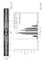
- FIG. 12D is a dose distribution histogram associated with the simulation of FIGS. 12A-12C ;
- FIGS. 13A-13B are schematic illustrations of light flux distribution within a stainless steel conduit based on computer simulations according to embodiments of the invention.
- FIG. 13C is a dose distribution histogram associated with the simulation of FIGS. 13A-13B .
- Some demonstrative embodiments of the invention include an ultraviolet (UV) disinfection system having a conduit to carry liquid to be disinfected and an illumination source located inside a transparent sleeve positioned substantially perpendicular to the longitudinal axis of symmetry of the conduit and the direction of flow of the liquid.
- UV ultraviolet
- the liquid disinfection process may include inactivation or removal of any organism, bacteria, microorganism, being, creature, microbe, germ, virus, organic contaminator, non-organic contaminator, oxidizeable toxic or contaminator; any cumulative noxious species of biological or chemical origin; any oxidizing particle, fragment or element, e.g., Hydrogen peroxide or Titanium dioxide, intended to oxidize a contaminator and/or the like.
- Some demonstrative embodiments of the invention may refer to using ultraviolet (UV) light to disinfect the liquid and/or to oxidize particles within the liquid.
- UV ultraviolet
- light of any other suitable spectrum may be used.
- a disinfection system 100 may include a tube or conduit 101 to carry liquid to be disinfected, one or more substantially light-transparent sleeves 102 positioned within conduit 101 substantially perpendicular to its longitudinal axis of symmetry 109 and one or more light sources 104 , each positioned within a respective sleeve 102 .
- light sources 104 may be UV light sources capable of emitting light at 254 nm.
- Conduit 101 may have an inlet 106 to receive from an external liquid pipe the liquid to be disinfected and an outlet 108 to discharge the liquid via an external discharge pipe.
- System 100 may further include adaptors 110 to connect conduit 101 to the external liquid pipes.
- the adaptors may comprise O-rings to ensure water-tight connections between the external pipes and the conduit.
- Conduit 101 may be substantially made of UV-transparent glass, such as quartz.
- UV-transparent sleeves 102 may be for example quartz or Teflon® sleeves.
- Each Sleeve 102 may have external dimensions smaller than the internal dimensions of conduit 101 such that liquid may flow within conduit 101 around sleeves 102 .
- Both ends of sleeve 102 may extend from the walls of conduit 101 to enable replacement of light source 104 within sleeve 102 .
- Light sources 104 may illuminate the liquid to be disinfected when flowing in the conduit.
- the liquid within conduit 101 may act as a waveguide and at least part of the light, for example, at least half of the emitted UV intensity, may be totally-internally reflected at the interface of the UV-transparent conduit 101 and the air surrounding it.
- Conduit 101 may be located inside a protective metal sleeve with an air gap between the conduit and the sleeve, as shown for example, in FIG. 2B .
- the total internal reflection (TIR) effect is demonstrated in
- light source 104 may generate UV light of a suitable UV-germicidal spectrum.
- light source 104 may include one or more UV lamps, e.g., a low-pressure UV lamp, a low-pressure high output UV lamp, a medium-pressure UV lamp, a high-pressure UV lamp, and/or a microwave-excited UV lamp, as are all known in the art.
- the liquid may act as a waveguide and at least part of the light, for example, at least half of the emitted UV intensity, may be totally-internally reflected at the interface of the glass conduit and air surrounding it. According to other embodiments of the invention, at least 70% of the emitted UV intensity may be totally-internally reflected at the interface of the glass conduit and air surrounding it.
- the liquid to be disinfected may flow around each of light sources 104 .
- the system may include an additional light source to enable disinfection of the liquid to the required level even when one of the light sources 104 is fully or partially dysfunctional. For example, the disinfection process may continue while a non-functional light source is being replaced or fixed.
- embodiments of the present invention in which light sources 104 are located substantially perpendicular to the direction of flow of the liquid within conduit 101 may ensure that each light source is capable of illuminating substantially the entire flow of liquid when the flow traverses that particular light source.
- An exemplary disinfection system 200 may include a substantially UV-transparent conduit 201 to carry liquid to be disinfected, substantially UV-transparent sleeves 202 A and 202 B positioned within conduit 201 substantially perpendicular to its axis of symmetry 209 and one or more UV-light sources 204 , each positioned within a respective sleeve 202 .
- sleeves 202 A and 202 B are orthogonal to each other.
- UV-transparent sleeves 202 may be positioned with respect to each other, at any rotational angle around the longitudinal axis of symmetry 209 of conduit 201 . According to other embodiments of the present invention, UV-transparent sleeves 202 may be positioned at any rotational angle around other axis of symmetry of conduit 201 . Although a symmetrical cylinder-shaped conduit is shown, it should be understood to a man skilled in the art that the conduit may have other shapes, not necessarily symmetrical, as described in detail with respect to FIG. 5A-5C .
- Conduit 201 may be located inside a protective metal tube 203 forming an air gap 208 between conduit 201 and metal tube 203 .
- external tube 103 may include a see-through window 210 made of transparent material such as glass, plastic or any other suitable material to enable an operator to view conduit 201 and a cover 212 to cover window 210 when desired.
- a see-through window 210 made of transparent material such as glass, plastic or any other suitable material to enable an operator to view conduit 201 and a cover 212 to cover window 210 when desired.
- a single see-through window is shown, it should be understood to a person skilled in the art that the invention is not limited in this respect and according to embodiments of the present invention tube 203 may include more than one see-through window at any size and/or shape.
- FIG. 3 depicts an exemplary illustration of a conduit having four sleeves according to some demonstrative embodiments of the invention.
- the exemplary conduit 301 of FIG. 3 includes four UV-transparent sleeves 302 A- 302 D positioned within conduit 301 substantially perpendicular to its longitudinal axis of symmetry 309 .
- pairs of adjacent sleeves are orthogonal to each other.
- sleeves 302 A and 302 B are orthogonal to each other; sleeves 302 B and 302 C are orthogonal to each other; and sleeves 302 C and 302 D.
- pairs of alternating sleeves are parallel to each other.
- sleeves 302 A and 302 C are parallel to each other; and likewise sleeves 302 B and 302 D are parallel to each other.
- UV-transparent sleeves 302 may be positioned with respect to each other, at any rotational angle around the axis of symmetry 309 of conduit 301 .
- Sleeves may be fused to conduit 301 to form a single glass structure.
- sleeve 202 may be attached to conduit 301 using housing, adaptors, connectors or any suitable means known in the art.
- each of areas 316 A- 316 D may be a metal housing for one of sleeves 302 A- 302 D.
- the metal housing may be coated on its interior surface with a reflective coating to increase the efficiency of the disinfection process.
- the reflective coating may be coated with a UV-transparent, UV resistive and bio-compatible coating, for example a Teflon® coating.
- the sleeves are illustrated as being cylindrical, it should, be understood to a person skilled in the art that embodiments of the invention are not limited in this respect and the sleeve may have other suitable shapes, such as hydrodynamic shapes, as detailed below with respect to FIG. 7 .
- FIG. 4 conceptually illustrates a side view of an exemplary conduit having a reflective coating on portions of its surface according to some embodiments of the invention.
- a sleeve 402 may be positioned within conduit 401 such that sleeve 402 is substantially perpendicular to the longitudinal axis of symmetry 409 of conduit 401 .
- UV-light source 404 may be positioned within sleeve 402 .
- the liquid may act as a waveguide and at least part of the light, for example, rays 410 and 411 may be totally-internally reflected at the interface of conduit 401 and the air surrounding it 408 .
- Conduit 401 may include one or more mirrors or UV reflective coating areas 407 to reflect non-guided rays, for example, ray 412 back into the liquid.
- At least portions of the exterior surface of conduit 401 may be coated with UV reflective coating 407 to produce rear surface mirror effect, e.g., to allow a larger portion of the light from light source 404 to illuminate the liquid flowing in conduit 401 .
- Coating 407 may reflect back into the liquid additional light rays reaching the surface in relative proximity to sleeve 402 .
- Reflective coating 407 may comprise aluminum deposition, gold deposition or multi-layer dielectric material. Any other suitable reflective coating may be used.
- the entire surface of the conduit may be coated with reflective coating to enhance the back-mirror effect.
- conduit 401 may be from a material having UV-reflection properties, for example, aluminum or any other metal.
- Reflecting area 414 may reflect back into the liquid non-guided light rays that cannot undergo TIR, such as ray 413 .
- Reflecting area 414 may include a UV-reflecting coating on its inner surface or may be covered by a thin sheet made of material having UV-reflecting properties. The UV-reflecting coating or sheet may be protected against water damage by coating it with a UV-resistive, UV-transparent coating such as Teflon®.
- FIGS. 5A, 5B and 5C depict schematic illustrations of conduits having varying diameters along their lengths according to some demonstrative embodiments of the invention.
- the shape of the conduit may be pre-determined to increase the efficiency of the disinfection process.
- the internal diameter of conduit 501 may vary along its length, as depicted in the demonstrative illustration of FIGS. 5A, 5B and 5C .
- the specific shape of the conduit may affect the liquid flow pattern and the shape may be pre-determined in order to increase the overall efficiency of the disinfection system. It should be understood that conduit 501 may have any other symmetrical or non-symmetrical shape.
- FIGS. 6A and 6B depict schematic illustrations of a portion of disinfection systems having flow-forming objects according to some embodiments of the present invention.
- Each of disinfection systems 600 A and 600 B may include a conduit 601 to carry liquid to be disinfected, a substantially UV-transparent sleeves 602 positioned within conduit 601 substantially perpendicular to its longitudinal axis of symmetry and a UV-light sources 604 positioned within sleeve 602 .
- Conduit 601 may include one or more objects 614 affixed to the conduit. As illustrated in FIG. 6A , objects 614 may be attached to a protrusion to be located in relative distance from the surface of the conduit. As illustrated in FIG.
- objects 614 may be attached to the surface of the conduit or located in relative proximity to the surface. Objects 614 may be pre-designed and may be located in specific positions in conduit 601 to affect the liquid flow pattern. Additionally or alternatively, UV-transparent objects and/or UV-scattering objects and/or UV-reflective objects may be affixed, attached or added to conduit 601 .
- the flow-forming objects may affect the liquid flux and the distribution of liquid tracks and the objects shape and location may be pre-determined in order to increase the overall efficiency of the disinfection process.
- the light scattering objects and/or light reflective objects may influence the spatial distribution of UV light intensity and the objects shape and location may be pre-determined in order to increase the overall efficiency of the disinfection process.
- sleeve 702 may have a hydrodynamic shape to prevent the formation of liquid stagnation zone where liquid may flow at a low velocity in proximity to sleeve 702 at the area facing the outlet of the conduit.
- the specific shape of sleeve 702 may be designed to improve light distribution and liquid flow pattern in order to increase the overall efficiency of the disinfection system.
- sleeve 702 having a non-cylindrical shape may be positioned within a substantially UV-transparent conduit substantially perpendicular to the direction of liquid flow.
- the non-cylindrical sleeve may be positioned within non-transparent containers such as stainless steel conduits or reactors.
- FIG. 8 is a conceptual illustration of an exemplary disinfection system having a patterned sleeve according to some demonstrative embodiments of the invention.
- a sleeve 802 may be positioned within conduit 801 such that sleeve 802 is substantially perpendicular to the longitudinal axis of symmetry of conduit 801 .
- UV-light source 804 may be positioned within sleeve 802 .
- the liquid may act as a waveguide and at least part of the light may be totally-internally reflected at the interface of conduit 801 and its surroundings.
- conduit 801 may include one or more mirrors or UV reflective coating areas 807 to reflect rays back into the liquid. Still, certain rays may evade both TIR and the UV reflective areas.
- sleeve 802 may include one or more objects 805 located in specific positions and shaped in order to influence the light distribution inside conduit 801 .
- Object 805 may be UV-scattering or UV-reflecting objects made of any suitable material.
- ray 820 is directed toward area 821 , which is not coated with reflective coating. Accordingly, in a non-patterned sleeve such a ray would traverse the liquid for a short distance before exiting the conduit via area 821 . Instead by using sleeve 802 , ray 820 may hit object 805 , change its direction (arrow 822 ) and reach reflective area 807 to be reflected back into the liquid.
- the patterned sleeve is described as being positioned within a substantially UV-transparent conduit substantially perpendicular to the direction of liquid flow, it should, be understood to a person skilled in the art that embodiments of the invention are not limited in this respect and embodiments of the invention are likewise applicable to using such a patterned sleeve at any position relative to the liquid flow within any container or conduit including non-transparent containers such as stainless steel conduits or reactors.
- FIG. 9 is a conceptual illustration of an exemplary disinfection system having a non-cylindrical light source according to some demonstrative embodiments of the invention.
- a sleeve 902 may be positioned within conduit 901 such that sleeve 902 is substantially perpendicular to the longitudinal axis of symmetry of conduit 901 .
- UV-light source 904 may be positioned within sleeve 902 .
- the liquid may act as a waveguide and at least part of the light may be totally-internally reflected at the interface of conduit 901 and its surroundings.
- conduit 901 may include one or more mirrors or UV reflective coating areas 907 to reflect rays back into the liquid.
- Light source 904 may have a non-cylindrical geometry; for example, its cross section may be an ellipse or any other desired shape to generated controlled light distribution.
- the shape of the lamp may be directed to generate a non-circular light distribution such that more light rays would be directed to the direction of the liquid flow than to the surface of conduit 901 .
- the specific shape of light source 904 may be designed according to the specific characteristics of the system's geometry and the disinfection process in order to increase the overall efficiency of the disinfection system.
- non-cylindrical light source is described as being positioned within a substantially UV-transparent conduit substantially perpendicular to the direction of liquid flow, it should, be understood to a person skilled in the art that embodiments of the invention are not limited in this respect and embodiments of the invention are likewise applicable to using such a light source at any position relative to the liquid flow within any container or conduit including non-transparent containers such as stainless steel conduits or reactors.
- a disinfection system 140 may include a conduit 141 to carry liquid to be disinfected.
- Conduit 141 may include more than one branch, for example two branches, 143 A and 143 B to increase the liquid flow. Having more than one branch may enable better control of the internal pressure in conduit 141 .
- Conduit 141 may have an inlet 146 to receive from an external liquid pipe the liquid to be disinfected and an outlet 148 to discharge the liquid via an external discharge pipe.
- System 140 may include one or more substantially UV-transparent sleeves 142 A positioned within branch 143 A substantially perpendicular to its longitudinal axis of symmetry 149 A and one or more UV-light sources 144 A, each positioned within a respective sleeve 142 A.
- System 140 may further include one or more substantially UV-transparent sleeves 142 B positioned within branch 143 B substantially perpendicular to its longitudinal axis of symmetry 149 B and one or more UV-light sources 144 B, each positioned within a respective sleeve 142 B.
- FIGS. 11A-11C demonstrate the modular nature of an exemplary disinfection system according to embodiments of the invention.
- the liquid flow section of the disinfection system may be constructed from two types of modular building blocks, conduit elements 151 and sleeve elements 152 .
- Sleeve elements 152 may include a ring 153 having a UV-transparent sleeve 154 positioned within. The internal diameter or ring 153 is larger than the external diameter of sleeve 154 .
- Element 152 may further include a UV-light source positioned within sleeve 154 . Both ends of element 152 may include adaptors, connectors or a screw mechanism to be connected to one or more of conduits 151 .
- Conduit elements 151 may be substantially made of UV-transparent material, such as quartz as described in detail above.
- the external diameter of conduit 151 may be substantially similar to the external diameter of ring 153 .
- Both ends of conduits 151 may include adaptors, connectors or a screw mechanism to be connected to one or more of elements 152 .
- the connections between conduits 151 and sleeve parameters 152 may be water-tight connections.
- At least one sleeve element 152 and two conduit elements 151 may create a conduit set to carry liquid to be disinfected as described above.
- a conduit set may comprise a number of n sleeve elements 152 and a number of n+1 conduit elements 151 .
- conduit 150 may comprise one sleeve element 152 and two conduit elements 151 .
- conduit 160 may comprise two sleeve elements 152 and three conduit elements 151 .
- conduits 150 and 160 are shown, it should be understood to a person skilled in the art that the invention is not limited in this respect and according to embodiments of the present invention any combination of n+1 conduit elements 151 and n sleeve elements 152 may be connected to create a conduit set.
- embodiments of the present invention are not limited in this respect, it is understood and simulated that a pre-designed structure according to embodiments of the present invention improves the efficiency of UV disinfection and increase kill probability, namely the probability to inactivate the entities being in the liquid flowing in conduit 101 .
- illumination-flux distributions in accordance with some demonstrative embodiments of the invention. It should be noted that the illumination-flux distributions used in these examples are not intended to limit the scope of the invention to any particular configuration and/or illumination flux distribution.
- FIGS. 12A-12C illustrate computer simulations of light flux distribution within an exemplary conduit during a liquid disinfection process.
- the simulated system is an exemplary system according to embodiments of the invention.
- the system includes one UV light source within a quartz sleeve positioned in the center of a quartz conduit such that the sleeve is perpendicular to the longitudinal axis of symmetry of the conduit defining the Z direction.
- the longitudinal axis of the sleeve defined the X direction.
- the calculations were performed for a flow of liquid of 50 m 3 /h.
- the liquid used for the computer simulations was clear water with UVT (ultraviolet transmission) of 98%.
- FIG. 12A is a cross section in the Y-Z plane of a portion of the conduit illustrating the light flux distribution between the light source and the outlet end of the conduit.
- FIG. 12B is a cross section in the X-Z plane of the same portion of the conduit illustrating the light flux distribution between the light source and the outlet end of the conduit.
- FIG. 12C is a cross section in the Y-Z plane of the entire conduit illustrating the light flux distribution between the inlet end and the outlet end of the conduit. As can be seen, the light reaches trough the entire length of the tube at a substantial intensity.
- FIG. 12D shows a graph illustrating the calculated normalized UV dose distribution within the quartz conduit. The normalized dose distribution function is closed to being a Gaussian function.
- FIGS. 13A and 13B illustrate computer simulations of light flux distribution within a conventional stainless steel container having 20% reflection during a liquid disinfection process. All the other parameters used in the comparative simulation were similar to the simulations of FIGS. 12A-12C . As can be seen, the intensity of light is practically zero after 50 mm is the Z direction.
- FIG. 13C shows a graph illustrating the UV dose distribution within the conventional stainless steel conduit. As expected, the average dose within the stainless steel conduit having a value of ⁇ 48 [mJ/cm 2 ] ⁇ is much smaller than the average dose of the quartz conduit with a value of ⁇ 228 [mJ/cm 2 ] ⁇ . The dose distribution of the conventional stainless steel conduit is wider than dose distribution of the quartz conduit.
Landscapes
- Health & Medical Sciences (AREA)
- Life Sciences & Earth Sciences (AREA)
- Organic Chemistry (AREA)
- Hydrology & Water Resources (AREA)
- Engineering & Computer Science (AREA)
- Environmental & Geological Engineering (AREA)
- Water Supply & Treatment (AREA)
- Chemical & Material Sciences (AREA)
- Toxicology (AREA)
- General Health & Medical Sciences (AREA)
- Animal Behavior & Ethology (AREA)
- Epidemiology (AREA)
- Public Health (AREA)
- Veterinary Medicine (AREA)
- Apparatus For Disinfection Or Sterilisation (AREA)
- Physical Water Treatments (AREA)
- Non-Portable Lighting Devices Or Systems Thereof (AREA)
- Infusion, Injection, And Reservoir Apparatuses (AREA)
- Optical Elements Other Than Lenses (AREA)
Abstract
Description
Claims (2)
Priority Applications (2)
Application Number | Priority Date | Filing Date | Title |
---|---|---|---|
US15/137,191 US10427954B2 (en) | 2006-11-14 | 2016-04-25 | Method and apparatus for liquid disinfection using light transparent conduit |
US16/132,434 US10494273B2 (en) | 2006-11-14 | 2018-09-16 | Method and apparatus for liquid disinfection using light transparent conduit |
Applications Claiming Priority (5)
Application Number | Priority Date | Filing Date | Title |
---|---|---|---|
US85872706P | 2006-11-14 | 2006-11-14 | |
PCT/IL2007/001409 WO2008059503A1 (en) | 2006-11-14 | 2007-11-14 | Method and apparatus for liquid disinfection using light transparent conduit |
US11/917,878 US20100264329A1 (en) | 2006-11-14 | 2007-11-14 | Method and apparatus for liquid disinfection using light transparent conduit |
US13/892,328 US9320818B2 (en) | 2006-11-14 | 2013-05-13 | Method and apparatus for liquid disinfection using light transparent conduit |
US15/137,191 US10427954B2 (en) | 2006-11-14 | 2016-04-25 | Method and apparatus for liquid disinfection using light transparent conduit |
Related Parent Applications (1)
Application Number | Title | Priority Date | Filing Date |
---|---|---|---|
US13/892,328 Continuation US9320818B2 (en) | 2006-11-14 | 2013-05-13 | Method and apparatus for liquid disinfection using light transparent conduit |
Related Child Applications (1)
Application Number | Title | Priority Date | Filing Date |
---|---|---|---|
US16/132,434 Continuation US10494273B2 (en) | 2006-11-14 | 2018-09-16 | Method and apparatus for liquid disinfection using light transparent conduit |
Publications (2)
Publication Number | Publication Date |
---|---|
US20160236948A1 US20160236948A1 (en) | 2016-08-18 |
US10427954B2 true US10427954B2 (en) | 2019-10-01 |
Family
ID=39048009
Family Applications (4)
Application Number | Title | Priority Date | Filing Date |
---|---|---|---|
US11/917,878 Abandoned US20100264329A1 (en) | 2006-11-14 | 2007-11-14 | Method and apparatus for liquid disinfection using light transparent conduit |
US13/892,328 Active US9320818B2 (en) | 2006-11-14 | 2013-05-13 | Method and apparatus for liquid disinfection using light transparent conduit |
US15/137,191 Active US10427954B2 (en) | 2006-11-14 | 2016-04-25 | Method and apparatus for liquid disinfection using light transparent conduit |
US16/132,434 Active US10494273B2 (en) | 2006-11-14 | 2018-09-16 | Method and apparatus for liquid disinfection using light transparent conduit |
Family Applications Before (2)
Application Number | Title | Priority Date | Filing Date |
---|---|---|---|
US11/917,878 Abandoned US20100264329A1 (en) | 2006-11-14 | 2007-11-14 | Method and apparatus for liquid disinfection using light transparent conduit |
US13/892,328 Active US9320818B2 (en) | 2006-11-14 | 2013-05-13 | Method and apparatus for liquid disinfection using light transparent conduit |
Family Applications After (1)
Application Number | Title | Priority Date | Filing Date |
---|---|---|---|
US16/132,434 Active US10494273B2 (en) | 2006-11-14 | 2018-09-16 | Method and apparatus for liquid disinfection using light transparent conduit |
Country Status (8)
Country | Link |
---|---|
US (4) | US20100264329A1 (en) |
EP (3) | EP2527302B1 (en) |
JP (3) | JP5174031B2 (en) |
CN (3) | CN101588994A (en) |
BR (1) | BRPI0717199B1 (en) |
DK (3) | DK2121525T3 (en) |
MX (1) | MX2009005082A (en) |
WO (1) | WO2008059503A1 (en) |
Cited By (2)
Publication number | Priority date | Publication date | Assignee | Title |
---|---|---|---|---|
US11007292B1 (en) | 2020-05-01 | 2021-05-18 | Uv Innovators, Llc | Automatic power compensation in ultraviolet (UV) light emission device, and related methods of use, particularly suited for decontamination |
US11997991B2 (en) | 2020-02-17 | 2024-06-04 | Atlantium Technologies Ltd. | Immune-enhanced aquaculture |
Families Citing this family (32)
Publication number | Priority date | Publication date | Assignee | Title |
---|---|---|---|---|
EP2527302B1 (en) | 2006-11-14 | 2018-05-16 | Atlantium Technologies Ltd. | Apparatus for liquid disinfection using light transparent conduit |
DE102007018670A1 (en) | 2007-04-18 | 2008-10-23 | Wedeco Ag | Device for germinating ballast water in ship by ultraviolet radiation, comprises a pump line through which ballast water is received and discharged and which is interfused by two groups of ultraviolet transparent cladding tubes |
CN101896264A (en) * | 2007-12-14 | 2010-11-24 | 特洛伊科技有限公司 | Radiation source assembly and fluid handling system |
DE102008051798B3 (en) * | 2008-10-17 | 2009-10-08 | Wedeco Ag | UV reactor for chemical reactions and its use |
US10973656B2 (en) | 2009-09-18 | 2021-04-13 | Spinal Surgical Strategies, Inc. | Bone graft delivery system and method for using same |
CN102276013B (en) * | 2010-06-08 | 2014-01-22 | 鸿富锦精密工业(深圳)有限公司 | Liquid purification device |
US9592374B2 (en) * | 2010-09-01 | 2017-03-14 | Becton, Dickinson And Company | Catheter adapter having UV-C antimicrobial radiation source and access window within catheter lumen for intravenous therapy |
US20120061585A1 (en) * | 2010-09-15 | 2012-03-15 | Takeshi Ide | Ultraviolet water treating apparatus |
DE102011111367B4 (en) * | 2011-08-29 | 2014-11-06 | Heraeus Noblelight Gmbh | Plant for sterilization or treatment of a liquid by means of UVC radiation and suitable emitter module |
DE102012109930A1 (en) | 2012-10-18 | 2014-04-24 | Heraeus Noblelight Gmbh | Emitter unit for generating ultraviolet radiation and method for its production |
DE102012022326A1 (en) | 2012-11-15 | 2014-05-15 | Schott Ag | Compact UV disinfection system with high homogeneity of the radiation field |
CN105164056B (en) * | 2013-01-24 | 2017-09-29 | 安特蓝德公司 | The method and apparatus for carrying out liquid disinfection for the light by launching from light emitting diode |
DK2969966T3 (en) * | 2013-03-15 | 2018-08-13 | Atlantium Tech Ltd | SYSTEM AND PROCEDURE FOR INACTIVATING INFECTIOUS PANCREAS CROSSVIRUS (IPNV) USING OPTIMIZED ULTRAVIOLET (UV) LIGHT |
JP6312812B2 (en) * | 2013-05-21 | 2018-04-18 | フィリップス ライティング ホールディング ビー ヴィ | Optical fluid processing equipment |
US9415126B2 (en) * | 2013-05-23 | 2016-08-16 | Sensor Electronic Technology, Inc. | Reflective transparent optical chamber |
JP2015033669A (en) * | 2013-08-08 | 2015-02-19 | 旭有機材工業株式会社 | Uv sterilization apparatus |
US11359397B2 (en) | 2014-01-21 | 2022-06-14 | Egon GRUBER | Device for disinfecting water |
AT515339A1 (en) * | 2014-01-21 | 2015-08-15 | Egon Gruber | Device for disinfecting water |
EP3262087B1 (en) | 2015-02-27 | 2023-11-01 | SABIC Global Technologies B.V. | Methods for improving the base color of plastic by reducing biological growth in the latex system |
US10077194B2 (en) * | 2015-05-14 | 2018-09-18 | Kavo Dental Technologies, Llc | Treatment system for liquids and interior surfaces of a fixture |
US10137213B2 (en) | 2015-05-14 | 2018-11-27 | Kavo Dental Technologies, Llc | UV disinfecting system for a dental operatory |
EP3354288B1 (en) * | 2015-09-25 | 2023-10-11 | Seoul Viosys Co. Ltd. | Sterilization apparatus |
CN107619086A (en) * | 2016-07-13 | 2018-01-23 | 紫岳科技有限公司 | UV disinfection system |
EP3497136B1 (en) | 2016-08-12 | 2020-12-16 | SABIC Global Technologies B.V. | Process for the production of polymers via emulsion polymerisation |
JP6710139B2 (en) | 2016-10-11 | 2020-06-17 | 日機装株式会社 | Sterilizer |
US10414524B2 (en) * | 2017-03-07 | 2019-09-17 | Owens-Brockway Glass Container Inc. | Peelable foil container closure having a wavy edge |
JP6885279B2 (en) * | 2017-09-22 | 2021-06-09 | 東芝ライテック株式会社 | Fluid sterilizer |
US10258715B1 (en) * | 2018-02-26 | 2019-04-16 | Rayvio Corporation | Ultraviolet disinfection system |
JP2019176986A (en) * | 2018-03-30 | 2019-10-17 | 旭化成株式会社 | Sterilizer |
KR102604128B1 (en) * | 2019-02-08 | 2023-11-17 | 더블유.엘. 고어 앤드 어소시에이트스, 인코포레이티드 | ultraviolet disinfection system |
KR102276303B1 (en) * | 2020-02-11 | 2021-07-12 | (주)포인트엔지니어링 | Uv sterilizer |
US11305032B2 (en) * | 2020-05-29 | 2022-04-19 | Stanley W. Ellis | Ultraviolet air irradiation system and ultraviolet air irradiation process |
Citations (60)
Publication number | Priority date | Publication date | Assignee | Title |
---|---|---|---|---|
US2776565A (en) | 1953-02-05 | 1957-01-08 | Honeywell Regulator Co | Fluid flow measuring apparatus |
US3637342A (en) * | 1969-05-07 | 1972-01-25 | Louis P Veloz | Sterilization of fluids by ultraviolet radiation |
US3672823A (en) | 1970-03-25 | 1972-06-27 | Wave Energy Systems | Method of sterilizing liquids |
US3894236A (en) | 1973-12-10 | 1975-07-08 | Wayne K Hazelrigg | Device for irradiating fluids |
DE2622637A1 (en) | 1976-05-20 | 1977-11-24 | Franz Boehnensieker | Water sterilised by ultraviolet emitters in pipe - esp. of quartz with external reflective coating esp. of aluminium |
US4149228A (en) | 1977-07-22 | 1979-04-10 | The United States Of America As Represented By The Secretary Of The Army | Compact uniform light diffuser and attenuator |
US4237008A (en) | 1979-01-11 | 1980-12-02 | Fischer & Porter Co. | Gravity flow disinfection contactor |
GB1584385A (en) | 1976-06-16 | 1981-02-11 | Bbc Brown Boveri & Cie | Apparatus for the sterilisation of liquids by means of ultra-violet radiation |
US4367410A (en) | 1979-07-09 | 1983-01-04 | Pure Water Systems, Inc. | Waste purification apparatus and method |
US4473866A (en) | 1981-10-28 | 1984-09-25 | Davis Murray A | Vehicle light system |
JPS6063050A (en) | 1983-09-16 | 1985-04-11 | 株式会社豊振科学産業所 | Fluid sterilizer |
DE3828026A1 (en) | 1988-08-18 | 1990-02-22 | Franz Boehnensieker | Device for the hygienic processing of liquids |
JPH0455353A (en) | 1990-06-22 | 1992-02-24 | Nippon Cement Co Ltd | Quick-hardening admixture of cement |
US5124131A (en) | 1990-12-10 | 1992-06-23 | Ultraviolet Energy Generators, Inc. | Compact high-throughput ultraviolet processing chamber |
US5227637A (en) | 1991-04-10 | 1993-07-13 | Thera Patent Gmbh & Co. Kg | Apparatus for irradiating fluids |
US5261874A (en) | 1991-09-16 | 1993-11-16 | The United States Of America As Represented By The Administrator Of The National Aeronautics And Space Administration | Extra-corporeal blood access, sensing, and radiation methods and apparatuses |
US5355555A (en) | 1990-09-18 | 1994-10-18 | Christer Zarelius | Elongated bendable device |
US5503800A (en) | 1994-03-10 | 1996-04-02 | Uv Systems Technology, Inc. | Ultra-violet sterilizing system for waste water |
US5682400A (en) | 1995-09-27 | 1997-10-28 | Krasnov; Alexander V. | Supersonic and subsonic laser with high frequency discharge excitation |
US5785845A (en) | 1995-11-09 | 1998-07-28 | Colaiano; Robert | Water purifying system |
DE19714810A1 (en) | 1997-04-10 | 1998-10-15 | Samland Thomas Dipl Math | Disinfection of drinking water comprises concentration of UV radiation by mirrors or lenses and direction through transparent material |
JPH11216466A (en) | 1998-02-03 | 1999-08-10 | Shokuhin Sangyo Denshi Riyou Gijutsu Kenkyu Kumiai | Light sterilization device |
US5994705A (en) | 1995-05-09 | 1999-11-30 | Labatt Brewing Company Limited | Flow-through photo-chemical reactor |
US6083387A (en) | 1996-06-20 | 2000-07-04 | Burnham Technologies Ltd. | Apparatus for the disinfection of fluids |
US6193894B1 (en) | 1999-06-23 | 2001-02-27 | Brad C. Hollander | Methods and apparatus for disinfecting and sterilizing water in water dispensers using ultraviolet radiation |
US6228327B1 (en) | 1998-07-09 | 2001-05-08 | Molecucare, Inc. | Apparatus and method for simultaneously germicidally cleansing air and water |
US6403030B1 (en) | 2000-07-31 | 2002-06-11 | Horton, Iii Isaac B. | Ultraviolet wastewater disinfection system and method |
DE10101816A1 (en) | 2001-01-17 | 2002-07-18 | Peter Ueberall | Flat diffuser for altering cross section of flow in a flow channel has multiple single diffusers as divergent rectangular channels fitted alongside each other over the cross section of flow. |
JP2002336896A (en) | 2001-05-17 | 2002-11-26 | Kurabo Ind Ltd | Sludge solubilization system |
US20030010927A1 (en) | 2001-06-19 | 2003-01-16 | Horst Wedekamp | UV radiation device for treating fluids with a simplified radiation chamber |
US20030019764A1 (en) | 2000-08-11 | 2003-01-30 | H20 Technologies, Ltd. | Under the counter water treatment system |
US20030020785A1 (en) * | 2001-07-25 | 2003-01-30 | Xerox Corporation | Laser ablatable hydrophobic fluorine-containing graft copolymers |
US20030049809A1 (en) | 2000-11-13 | 2003-03-13 | Klaus Kaiser | Method of inactivating microorganisms in a fluid using ultraviolet radiation |
WO2003033413A1 (en) | 2001-10-17 | 2003-04-24 | Honeywell International, Inc. | Apparatus for disinfecting water using ultraviolet radiation |
US20030129105A1 (en) | 2002-01-07 | 2003-07-10 | Hilary Boehme | Ultraviolet water disinfection reactor for installing in an existing water pipeline |
US20030129054A1 (en) | 2002-01-04 | 2003-07-10 | Manning Robert F. | Methods and apparatus for cooling gas turbine nozzles |
CN2587850Y (en) | 2002-07-10 | 2003-11-26 | 福建新大陆环保科技有限公司 | Ultraviolet ray fluid sterilizing system |
US20040004044A1 (en) | 2002-07-03 | 2004-01-08 | Anderson Jeffrey J. | Water purifier using ultraviolet radiation |
US20040020862A1 (en) | 2002-03-14 | 2004-02-05 | Baca Anthony Michael | Laser water detection, treatment and notification systems and methods |
WO2004033375A1 (en) | 2002-10-09 | 2004-04-22 | Trojan Technologies Inc. | Ultraviolet fluid treatment system |
US20040109756A1 (en) | 2002-12-09 | 2004-06-10 | Mitsubishi Heavy Industries Ltd. | Gas turbine |
US6761270B2 (en) | 2000-08-17 | 2004-07-13 | E. Bayne Carew | Wave coil filter assembly |
US6773608B1 (en) | 1998-05-13 | 2004-08-10 | Uv Pure Technologies Inc. | Ultraviolet treatment for aqueous liquids |
US20040222163A1 (en) | 2001-10-17 | 2004-11-11 | Honeywell International Inc. | Apparatus for disinfecting water using ultraviolet radiation |
US20050003737A1 (en) | 2003-06-06 | 2005-01-06 | P.C.T. Systems, Inc. | Method and apparatus to process substrates with megasonic energy |
WO2005011753A1 (en) | 2003-08-04 | 2005-02-10 | Atlantium Lasers Limited | In-line treatment of liquids and gases by light iradiation |
US6871534B1 (en) | 1998-12-21 | 2005-03-29 | Mitsubishi Denki Kabushiki Kaisha | Flow rate measuring device |
US20050173351A1 (en) | 2002-04-01 | 2005-08-11 | Paris Neofotistos | Apparatus for irradiating fluids with uv |
US6940075B2 (en) | 2001-03-15 | 2005-09-06 | Christopher R. Schulz | Ultraviolet-light-based disinfection reactor |
US20060072318A1 (en) | 2003-10-01 | 2006-04-06 | Ultraviolet Devices, Inc. | Lamp standard |
US7160453B1 (en) | 2000-06-15 | 2007-01-09 | Mitsuboshi Belting Ltd. | Filter for removing contaminants from water |
US20070012883A1 (en) | 2005-07-15 | 2007-01-18 | Lam Ka D | Ultraviolet water sterilizer |
US20070114442A1 (en) | 2005-11-18 | 2007-05-24 | Jian Chen | Fluid ultraviolet sterilization system |
US20070163934A1 (en) | 2003-02-14 | 2007-07-19 | Kim Kyoung M | Sterilize valve and a water-purifying device using the same |
US20070274879A1 (en) | 2004-07-23 | 2007-11-29 | Uv Light Sciences Group, Inc. | Uv sterilizer |
US7303612B2 (en) | 2005-03-24 | 2007-12-04 | L2B Environmental Systems Inc. | UV reflective cavity and method of providing same |
US20070284315A1 (en) | 2006-06-11 | 2007-12-13 | Duncan Alexander Collins | The water disinfection apparatus |
US7329029B2 (en) | 2003-05-13 | 2008-02-12 | Light Prescriptions Innovators, Llc | Optical device for LED-based lamp |
WO2008059503A1 (en) | 2006-11-14 | 2008-05-22 | Atlantium Technologies Ltd. | Method and apparatus for liquid disinfection using light transparent conduit |
US10137213B2 (en) | 2015-05-14 | 2018-11-27 | Kavo Dental Technologies, Llc | UV disinfecting system for a dental operatory |
Family Cites Families (5)
Publication number | Priority date | Publication date | Assignee | Title |
---|---|---|---|---|
US1940580A (en) | 1931-08-11 | 1933-12-19 | Caddy Sydney Charles | Light reflecting lamp |
JPH077967Y2 (en) * | 1990-09-21 | 1995-03-01 | 中野 浩二 | UV irradiation device |
CN1169705A (en) * | 1994-10-17 | 1998-01-07 | 特洛伊人技术公司 | UV fluid treatment device and method |
JPH11386A (en) * | 1997-06-10 | 1999-01-06 | Shinei Kk | Ultraviolet sterilization unit |
JP2001212214A (en) * | 2000-02-07 | 2001-08-07 | Toshiba Corp | Uv sterilizer |
-
2007
- 2007-11-14 EP EP12179852.4A patent/EP2527302B1/en active Active
- 2007-11-14 WO PCT/IL2007/001409 patent/WO2008059503A1/en active Application Filing
- 2007-11-14 EP EP10172649.5A patent/EP2251306B1/en active Active
- 2007-11-14 DK DK07827382.8T patent/DK2121525T3/en active
- 2007-11-14 MX MX2009005082A patent/MX2009005082A/en active IP Right Grant
- 2007-11-14 US US11/917,878 patent/US20100264329A1/en not_active Abandoned
- 2007-11-14 EP EP07827382.8A patent/EP2121525B1/en active Active
- 2007-11-14 CN CNA200780046174XA patent/CN101588994A/en active Pending
- 2007-11-14 CN CN201410168028.6A patent/CN103922437B/en active Active
- 2007-11-14 CN CN2010102842720A patent/CN102010024B/en active Active
- 2007-11-14 JP JP2009536865A patent/JP5174031B2/en active Active
- 2007-11-14 BR BRPI0717199-4A patent/BRPI0717199B1/en active IP Right Grant
- 2007-11-14 DK DK10172649.5T patent/DK2251306T3/en active
- 2007-11-14 DK DK12179852.4T patent/DK2527302T3/en active
-
2013
- 2013-01-04 JP JP2013000219A patent/JP5345739B2/en active Active
- 2013-05-13 US US13/892,328 patent/US9320818B2/en active Active
- 2013-08-14 JP JP2013168553A patent/JP2013233547A/en active Pending
-
2016
- 2016-04-25 US US15/137,191 patent/US10427954B2/en active Active
-
2018
- 2018-09-16 US US16/132,434 patent/US10494273B2/en active Active
Patent Citations (63)
Publication number | Priority date | Publication date | Assignee | Title |
---|---|---|---|---|
US2776565A (en) | 1953-02-05 | 1957-01-08 | Honeywell Regulator Co | Fluid flow measuring apparatus |
US3637342A (en) * | 1969-05-07 | 1972-01-25 | Louis P Veloz | Sterilization of fluids by ultraviolet radiation |
US3672823A (en) | 1970-03-25 | 1972-06-27 | Wave Energy Systems | Method of sterilizing liquids |
US3894236A (en) | 1973-12-10 | 1975-07-08 | Wayne K Hazelrigg | Device for irradiating fluids |
DE2622637A1 (en) | 1976-05-20 | 1977-11-24 | Franz Boehnensieker | Water sterilised by ultraviolet emitters in pipe - esp. of quartz with external reflective coating esp. of aluminium |
GB1584385A (en) | 1976-06-16 | 1981-02-11 | Bbc Brown Boveri & Cie | Apparatus for the sterilisation of liquids by means of ultra-violet radiation |
US4149228A (en) | 1977-07-22 | 1979-04-10 | The United States Of America As Represented By The Secretary Of The Army | Compact uniform light diffuser and attenuator |
US4237008A (en) | 1979-01-11 | 1980-12-02 | Fischer & Porter Co. | Gravity flow disinfection contactor |
US4367410A (en) | 1979-07-09 | 1983-01-04 | Pure Water Systems, Inc. | Waste purification apparatus and method |
US4473866A (en) | 1981-10-28 | 1984-09-25 | Davis Murray A | Vehicle light system |
JPS6063050A (en) | 1983-09-16 | 1985-04-11 | 株式会社豊振科学産業所 | Fluid sterilizer |
DE3828026A1 (en) | 1988-08-18 | 1990-02-22 | Franz Boehnensieker | Device for the hygienic processing of liquids |
JPH0455353A (en) | 1990-06-22 | 1992-02-24 | Nippon Cement Co Ltd | Quick-hardening admixture of cement |
US5355555A (en) | 1990-09-18 | 1994-10-18 | Christer Zarelius | Elongated bendable device |
US5124131A (en) | 1990-12-10 | 1992-06-23 | Ultraviolet Energy Generators, Inc. | Compact high-throughput ultraviolet processing chamber |
US5227637A (en) | 1991-04-10 | 1993-07-13 | Thera Patent Gmbh & Co. Kg | Apparatus for irradiating fluids |
US5261874A (en) | 1991-09-16 | 1993-11-16 | The United States Of America As Represented By The Administrator Of The National Aeronautics And Space Administration | Extra-corporeal blood access, sensing, and radiation methods and apparatuses |
US5503800A (en) | 1994-03-10 | 1996-04-02 | Uv Systems Technology, Inc. | Ultra-violet sterilizing system for waste water |
US5994705A (en) | 1995-05-09 | 1999-11-30 | Labatt Brewing Company Limited | Flow-through photo-chemical reactor |
US5682400A (en) | 1995-09-27 | 1997-10-28 | Krasnov; Alexander V. | Supersonic and subsonic laser with high frequency discharge excitation |
US5785845A (en) | 1995-11-09 | 1998-07-28 | Colaiano; Robert | Water purifying system |
US6083387A (en) | 1996-06-20 | 2000-07-04 | Burnham Technologies Ltd. | Apparatus for the disinfection of fluids |
DE19714810A1 (en) | 1997-04-10 | 1998-10-15 | Samland Thomas Dipl Math | Disinfection of drinking water comprises concentration of UV radiation by mirrors or lenses and direction through transparent material |
JPH11216466A (en) | 1998-02-03 | 1999-08-10 | Shokuhin Sangyo Denshi Riyou Gijutsu Kenkyu Kumiai | Light sterilization device |
US6773608B1 (en) | 1998-05-13 | 2004-08-10 | Uv Pure Technologies Inc. | Ultraviolet treatment for aqueous liquids |
US6228327B1 (en) | 1998-07-09 | 2001-05-08 | Molecucare, Inc. | Apparatus and method for simultaneously germicidally cleansing air and water |
US6871534B1 (en) | 1998-12-21 | 2005-03-29 | Mitsubishi Denki Kabushiki Kaisha | Flow rate measuring device |
US6193894B1 (en) | 1999-06-23 | 2001-02-27 | Brad C. Hollander | Methods and apparatus for disinfecting and sterilizing water in water dispensers using ultraviolet radiation |
US7160453B1 (en) | 2000-06-15 | 2007-01-09 | Mitsuboshi Belting Ltd. | Filter for removing contaminants from water |
US6403030B1 (en) | 2000-07-31 | 2002-06-11 | Horton, Iii Isaac B. | Ultraviolet wastewater disinfection system and method |
US20030019764A1 (en) | 2000-08-11 | 2003-01-30 | H20 Technologies, Ltd. | Under the counter water treatment system |
US6761270B2 (en) | 2000-08-17 | 2004-07-13 | E. Bayne Carew | Wave coil filter assembly |
US20030049809A1 (en) | 2000-11-13 | 2003-03-13 | Klaus Kaiser | Method of inactivating microorganisms in a fluid using ultraviolet radiation |
DE10101816A1 (en) | 2001-01-17 | 2002-07-18 | Peter Ueberall | Flat diffuser for altering cross section of flow in a flow channel has multiple single diffusers as divergent rectangular channels fitted alongside each other over the cross section of flow. |
US6940075B2 (en) | 2001-03-15 | 2005-09-06 | Christopher R. Schulz | Ultraviolet-light-based disinfection reactor |
JP2002336896A (en) | 2001-05-17 | 2002-11-26 | Kurabo Ind Ltd | Sludge solubilization system |
US20030010927A1 (en) | 2001-06-19 | 2003-01-16 | Horst Wedekamp | UV radiation device for treating fluids with a simplified radiation chamber |
US20030020785A1 (en) * | 2001-07-25 | 2003-01-30 | Xerox Corporation | Laser ablatable hydrophobic fluorine-containing graft copolymers |
US20040222163A1 (en) | 2001-10-17 | 2004-11-11 | Honeywell International Inc. | Apparatus for disinfecting water using ultraviolet radiation |
WO2003033413A1 (en) | 2001-10-17 | 2003-04-24 | Honeywell International, Inc. | Apparatus for disinfecting water using ultraviolet radiation |
US20030129054A1 (en) | 2002-01-04 | 2003-07-10 | Manning Robert F. | Methods and apparatus for cooling gas turbine nozzles |
US20030129105A1 (en) | 2002-01-07 | 2003-07-10 | Hilary Boehme | Ultraviolet water disinfection reactor for installing in an existing water pipeline |
US20040020862A1 (en) | 2002-03-14 | 2004-02-05 | Baca Anthony Michael | Laser water detection, treatment and notification systems and methods |
US20050173351A1 (en) | 2002-04-01 | 2005-08-11 | Paris Neofotistos | Apparatus for irradiating fluids with uv |
US20040004044A1 (en) | 2002-07-03 | 2004-01-08 | Anderson Jeffrey J. | Water purifier using ultraviolet radiation |
CN2587850Y (en) | 2002-07-10 | 2003-11-26 | 福建新大陆环保科技有限公司 | Ultraviolet ray fluid sterilizing system |
US20040118786A1 (en) | 2002-10-09 | 2004-06-24 | Trojan Technologies Inc. | Fluid treatment system |
WO2004033375A1 (en) | 2002-10-09 | 2004-04-22 | Trojan Technologies Inc. | Ultraviolet fluid treatment system |
US20040109756A1 (en) | 2002-12-09 | 2004-06-10 | Mitsubishi Heavy Industries Ltd. | Gas turbine |
US20070163934A1 (en) | 2003-02-14 | 2007-07-19 | Kim Kyoung M | Sterilize valve and a water-purifying device using the same |
US7329029B2 (en) | 2003-05-13 | 2008-02-12 | Light Prescriptions Innovators, Llc | Optical device for LED-based lamp |
US20050003737A1 (en) | 2003-06-06 | 2005-01-06 | P.C.T. Systems, Inc. | Method and apparatus to process substrates with megasonic energy |
US20070207707A1 (en) | 2003-06-06 | 2007-09-06 | P.C.T. Systems, Inc. | Method and apparatus to process substrates with megasonic energy |
WO2005011753A1 (en) | 2003-08-04 | 2005-02-10 | Atlantium Lasers Limited | In-line treatment of liquids and gases by light iradiation |
US20060072318A1 (en) | 2003-10-01 | 2006-04-06 | Ultraviolet Devices, Inc. | Lamp standard |
US20070274879A1 (en) | 2004-07-23 | 2007-11-29 | Uv Light Sciences Group, Inc. | Uv sterilizer |
US7303612B2 (en) | 2005-03-24 | 2007-12-04 | L2B Environmental Systems Inc. | UV reflective cavity and method of providing same |
US20070012883A1 (en) | 2005-07-15 | 2007-01-18 | Lam Ka D | Ultraviolet water sterilizer |
US20070114442A1 (en) | 2005-11-18 | 2007-05-24 | Jian Chen | Fluid ultraviolet sterilization system |
US20070284315A1 (en) | 2006-06-11 | 2007-12-13 | Duncan Alexander Collins | The water disinfection apparatus |
WO2008059503A1 (en) | 2006-11-14 | 2008-05-22 | Atlantium Technologies Ltd. | Method and apparatus for liquid disinfection using light transparent conduit |
US9320818B2 (en) * | 2006-11-14 | 2016-04-26 | Atlantium Technologies Ltd | Method and apparatus for liquid disinfection using light transparent conduit |
US10137213B2 (en) | 2015-05-14 | 2018-11-27 | Kavo Dental Technologies, Llc | UV disinfecting system for a dental operatory |
Non-Patent Citations (3)
Title |
---|
Notice of Allowance dated Feb. 22, 2016 for corresponding U.S. Appl. No. 13/892,328. |
Notice of Allowance dated Sep. 22, 2014 for corresponding U.S. Appl. No. 13/892,328. |
Office Action dated Apr. 19, 2019 for corresponding U.S. Appl. No. 16/132,434. |
Cited By (6)
Publication number | Priority date | Publication date | Assignee | Title |
---|---|---|---|---|
US11997991B2 (en) | 2020-02-17 | 2024-06-04 | Atlantium Technologies Ltd. | Immune-enhanced aquaculture |
US11007292B1 (en) | 2020-05-01 | 2021-05-18 | Uv Innovators, Llc | Automatic power compensation in ultraviolet (UV) light emission device, and related methods of use, particularly suited for decontamination |
US11020502B1 (en) | 2020-05-01 | 2021-06-01 | Uv Innovators, Llc | Ultraviolet (UV) light emission device, and related methods of use, particularly suited for decontamination |
US11116858B1 (en) | 2020-05-01 | 2021-09-14 | Uv Innovators, Llc | Ultraviolet (UV) light emission device employing visible light for target distance guidance, and related methods of use, particularly suited for decontamination |
US11565012B2 (en) | 2020-05-01 | 2023-01-31 | Uv Innovators, Llc | Ultraviolet (UV) light emission device employing visible light for target distance guidance, and related methods of use, particularly suited for decontamination |
US11883549B2 (en) | 2020-05-01 | 2024-01-30 | Uv Innovators, Llc | Ultraviolet (UV) light emission device employing visible light for operation guidance, and related methods of use, particularly suited for decontamination |
Also Published As
Publication number | Publication date |
---|---|
US20160236948A1 (en) | 2016-08-18 |
US20140117250A1 (en) | 2014-05-01 |
JP2013066894A (en) | 2013-04-18 |
US20190031536A1 (en) | 2019-01-31 |
CN101588994A (en) | 2009-11-25 |
CN103922437B (en) | 2016-08-17 |
EP2527302B1 (en) | 2018-05-16 |
CN102010024B (en) | 2013-12-18 |
MX2009005082A (en) | 2009-10-13 |
CN102010024A (en) | 2011-04-13 |
JP5345739B2 (en) | 2013-11-20 |
CN103922437A (en) | 2014-07-16 |
JP5174031B2 (en) | 2013-04-03 |
US10494273B2 (en) | 2019-12-03 |
EP2121525A1 (en) | 2009-11-25 |
EP2527302A1 (en) | 2012-11-28 |
DK2251306T3 (en) | 2020-05-25 |
EP2251306A3 (en) | 2012-08-29 |
JP2013233547A (en) | 2013-11-21 |
DK2527302T3 (en) | 2018-08-13 |
BRPI0717199A2 (en) | 2013-10-15 |
EP2121525B1 (en) | 2015-11-11 |
US20100264329A1 (en) | 2010-10-21 |
EP2251306A2 (en) | 2010-11-17 |
JP2010509019A (en) | 2010-03-25 |
DK2121525T3 (en) | 2016-02-08 |
EP2251306B1 (en) | 2020-02-19 |
US9320818B2 (en) | 2016-04-26 |
BRPI0717199B1 (en) | 2018-06-05 |
WO2008059503A1 (en) | 2008-05-22 |
Similar Documents
Publication | Publication Date | Title |
---|---|---|
US10494273B2 (en) | Method and apparatus for liquid disinfection using light transparent conduit | |
US8414779B2 (en) | Method and apparatus for liquid disinfection using light transparent conduit | |
US20090285727A1 (en) | Illumination unit for liquid disinfection systems | |
JP6374403B2 (en) | Method and apparatus for liquid disinfection with light emitted from light emitting diodes | |
AU2006288709B2 (en) | Method, device and system of illumination-based disinfection | |
US20090289015A1 (en) | Back-surface mirrors for ultraviolet liquid disinfection systems | |
US20210206662A1 (en) | Water sterilizing tube | |
US20080311012A1 (en) | Transmissive window for hydrooptic disinfection system | |
JP2012210571A (en) | Method for treating fluid of ultraviolet treatment apparatus, and ultraviolet treatment apparatus |
Legal Events
Date | Code | Title | Description |
---|---|---|---|
AS | Assignment |
Owner name: ATLANTIUM TECHNOLOGIES LTD., ISRAEL Free format text: ASSIGNMENT OF ASSIGNORS INTEREST;ASSIGNORS:VARDIEL, ZOHAR;LEVY, URI;ROZENBERG, YTZHAK;SIGNING DATES FROM 20080421 TO 20080424;REEL/FRAME:039010/0940 |
|
STPP | Information on status: patent application and granting procedure in general |
Free format text: NOTICE OF ALLOWANCE MAILED -- APPLICATION RECEIVED IN OFFICE OF PUBLICATIONS |
|
STPP | Information on status: patent application and granting procedure in general |
Free format text: PUBLICATIONS -- ISSUE FEE PAYMENT VERIFIED |
|
STCF | Information on status: patent grant |
Free format text: PATENTED CASE |
|
MAFP | Maintenance fee payment |
Free format text: PAYMENT OF MAINTENANCE FEE, 4TH YR, SMALL ENTITY (ORIGINAL EVENT CODE: M2551); ENTITY STATUS OF PATENT OWNER: SMALL ENTITY Year of fee payment: 4 |