US10425256B2 - Methods and systems for interference mitigation in a dual-polarized communication system - Google Patents
Methods and systems for interference mitigation in a dual-polarized communication system Download PDFInfo
- Publication number
- US10425256B2 US10425256B2 US15/889,919 US201815889919A US10425256B2 US 10425256 B2 US10425256 B2 US 10425256B2 US 201815889919 A US201815889919 A US 201815889919A US 10425256 B2 US10425256 B2 US 10425256B2
- Authority
- US
- United States
- Prior art keywords
- signals
- adaptive
- filtering stage
- output signals
- interference mitigation
- Prior art date
- Legal status (The legal status is an assumption and is not a legal conclusion. Google has not performed a legal analysis and makes no representation as to the accuracy of the status listed.)
- Active
Links
Images


Classifications
-
- H—ELECTRICITY
- H04—ELECTRIC COMMUNICATION TECHNIQUE
- H04B—TRANSMISSION
- H04B7/00—Radio transmission systems, i.e. using radiation field
- H04B7/02—Diversity systems; Multi-antenna system, i.e. transmission or reception using multiple antennas
- H04B7/10—Polarisation diversity; Directional diversity
-
- H—ELECTRICITY
- H04—ELECTRIC COMMUNICATION TECHNIQUE
- H04L—TRANSMISSION OF DIGITAL INFORMATION, e.g. TELEGRAPHIC COMMUNICATION
- H04L25/00—Baseband systems
- H04L25/02—Details ; arrangements for supplying electrical power along data transmission lines
- H04L25/03—Shaping networks in transmitter or receiver, e.g. adaptive shaping networks
- H04L25/03006—Arrangements for removing intersymbol interference
- H04L25/03012—Arrangements for removing intersymbol interference operating in the time domain
- H04L25/03019—Arrangements for removing intersymbol interference operating in the time domain adaptive, i.e. capable of adjustment during data reception
- H04L25/03057—Arrangements for removing intersymbol interference operating in the time domain adaptive, i.e. capable of adjustment during data reception with a recursive structure
-
- H—ELECTRICITY
- H04—ELECTRIC COMMUNICATION TECHNIQUE
- H04B—TRANSMISSION
- H04B7/00—Radio transmission systems, i.e. using radiation field
- H04B7/002—Reducing depolarization effects
-
- H—ELECTRICITY
- H04—ELECTRIC COMMUNICATION TECHNIQUE
- H04B—TRANSMISSION
- H04B7/00—Radio transmission systems, i.e. using radiation field
- H04B7/02—Diversity systems; Multi-antenna system, i.e. transmission or reception using multiple antennas
- H04B7/04—Diversity systems; Multi-antenna system, i.e. transmission or reception using multiple antennas using two or more spaced independent antennas
- H04B7/0408—Diversity systems; Multi-antenna system, i.e. transmission or reception using multiple antennas using two or more spaced independent antennas using two or more beams, i.e. beam diversity
-
- H—ELECTRICITY
- H04—ELECTRIC COMMUNICATION TECHNIQUE
- H04L—TRANSMISSION OF DIGITAL INFORMATION, e.g. TELEGRAPHIC COMMUNICATION
- H04L25/00—Baseband systems
- H04L25/02—Details ; arrangements for supplying electrical power along data transmission lines
- H04L25/03—Shaping networks in transmitter or receiver, e.g. adaptive shaping networks
- H04L25/03006—Arrangements for removing intersymbol interference
- H04L25/03012—Arrangements for removing intersymbol interference operating in the time domain
- H04L25/03019—Arrangements for removing intersymbol interference operating in the time domain adaptive, i.e. capable of adjustment during data reception
- H04L25/03038—Arrangements for removing intersymbol interference operating in the time domain adaptive, i.e. capable of adjustment during data reception with a non-recursive structure
-
- H—ELECTRICITY
- H04—ELECTRIC COMMUNICATION TECHNIQUE
- H04L—TRANSMISSION OF DIGITAL INFORMATION, e.g. TELEGRAPHIC COMMUNICATION
- H04L25/00—Baseband systems
- H04L25/02—Details ; arrangements for supplying electrical power along data transmission lines
- H04L25/03—Shaping networks in transmitter or receiver, e.g. adaptive shaping networks
- H04L25/03006—Arrangements for removing intersymbol interference
- H04L25/03343—Arrangements at the transmitter end
-
- H—ELECTRICITY
- H04—ELECTRIC COMMUNICATION TECHNIQUE
- H04L—TRANSMISSION OF DIGITAL INFORMATION, e.g. TELEGRAPHIC COMMUNICATION
- H04L25/00—Baseband systems
- H04L25/02—Details ; arrangements for supplying electrical power along data transmission lines
- H04L25/03—Shaping networks in transmitter or receiver, e.g. adaptive shaping networks
- H04L25/03006—Arrangements for removing intersymbol interference
- H04L2025/03433—Arrangements for removing intersymbol interference characterised by equaliser structure
- H04L2025/03535—Variable structures
- H04L2025/03547—Switching between time domain structures
- H04L2025/03566—Switching between time domain structures between different tapped delay line structures
- H04L2025/03573—Switching between time domain structures between different tapped delay line structures between recursive and non-recursive
Definitions
- the present disclosure relates to dual-polarized communications systems and, in particular, to mitigation of interference present in such systems.
- the polarizations may not be perfectly orthogonal, which may lead to energy leakage from one stream to another and cause cross-polarization interference. Since the receivers for each of the polarizations are synchronized to the corresponding transmitter the interference from the other polarization may appear at the receiver for the other polarization with a certain frequency offset distortions that arises due to imperfections in the transmitter and receiver local oscillators (LOs) leading to additional phase noise. Furthermore, adopting higher-order modulation may render the communication system more sensitive to phase noise (PN).
- PN phase noise
- an interference mitigation apparatus comprising: an adaptive feedforward filtering stage and an adaptive feedback filtering stage configured to produce a plurality of output signals from a plurality of frequency downconverted signals, the output signals for being provided to a data decoding stage; a plurality of phase rotators configured to apply phase rotation to the downconverted signals prior to processing by the adaptive feedforward filtering stage and the adaptive feedback filtering stage; and an adaptive controller configured for varying an amount of the phase rotation applied by the phase rotators to the downconverted signals based at least in part on symbol decisions made on the output signals.
- an interference mitigation method comprising: downconverting a plurality of modulated signals of respective polarizations to produce a corresponding plurality of downconverted signals; processing the downconverted signals with an adaptive feedforward filtering stage and an adaptive feedback filtering stage to produce a corresponding one of a plurality of output signals, the output signals for being provided to a data decoding stage; and applying phase rotation to the downconverted signals prior to said processing, wherein an amount of the phase rotation applied to the downconverted signals is adaptively controlled based at least in part on symbol decisions made on the output signals.
- a communication system comprising: a transmitter configured to send a plurality of orthogonally polarized signals containing transmit data using faster-than-Nyquist transmission; and a receiver comprising a plurality of orthogonally polarized antennas to produce a corresponding plurality of received signals from a composite received version of the polarized signals, the receiver configured to process each of the received signals by (i) applying adaptively controlled amounts of phase rotation; (ii) processing with an adaptive feedforward filtering stage; and (iii) processing with an adaptive feedback stage to obtain output signals, whereby the output signals are decoded by a data decoding stage to obtain estimates of the transmit data.
- an interference mitigation method comprising: downconverting a plurality of modulated wireless signals of respective polarizations to produce a corresponding plurality of downconverted signals; processing each of the downconverted signals to produce a corresponding one of a plurality of output signals in which there is less inter-symbol-interference and cross-polarization interference than in the downconverted signal, the output signals for being provided to a data decoding stage; applying phase rotation to the downconverted signals prior to said processing, wherein an amount of phase rotation is adaptively controlled based at least in part on symbol decisions made on the output signals.
- an interference mitigating apparatus comprising: an inter-symbol-interference (ISI) mitigation portion with a plurality of inputs and a plurality of outputs, the inputs for receiving corresponding demodulated signals of respective polarizations; a cross-polarization interference (XPI) mitigation portion with a plurality of inputs and a plurality of outputs, the inputs being connected respectively to the outputs of the ISI mitigation portion, the outputs of the XPI mitigation portion for being provided to a data decoding stage; and a plurality of phase rotators for phase rotating the demodulated signals provided to the inputs of the ISI mitigation portion, the phase rotators being adaptively controlled based at least in part on symbol decisions made on the outputs of the XPI mitigation portion.
- ISI inter-symbol-interference
- XPI cross-polarization interference
- FIG. 1 is a block diagram illustrating certain components of a dual-polarization communication system, in accordance with an embodiment.
- FIG. 2 is a block diagram illustrating certain components of a transmit chain in the communication system of FIG. 1 , in accordance with an embodiment.
- FIG. 3A is a block diagram illustrating certain components of a receive chain in the communication system of FIG. 1 , including an interference mitigation apparatus, in accordance with an embodiment.
- FIG. 3B is a block diagram similar to FIG. 3A , except with matched filtering occurring in the digital domain.
- FIG. 4 is a block diagram illustrating certain components of the interference mitigation apparatus of FIGS. 3A and 3B , in a combined phase noise tracking (CPNT) embodiment.
- CPNT phase noise tracking
- FIG. 5 is a block diagram illustrating certain components of the interference mitigation apparatus of FIGS. 3A and 3B , in an independent phase noise tracking (IPNT) embodiment.
- IPNT phase noise tracking
- FIGS. 6 and 7 are plots of bit error rate versus signal-to-noise ratio in various implementations.
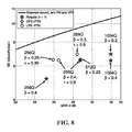
- FIG. 8 is a plot of spectral efficiency versus signal-to-noise ratio for various implementations.
- FIG. 9 plots the empirical complementary cumulative distribution function (CCDF) of instantaneous power for various implementations.
- CCDF empirical complementary cumulative distribution function
- FIG. 10 is a block diagram, similar to FIG. 2 , illustrating certain components of a transmit chain in the communication system of FIG. 1 , further including a pre-equalizer at the transmitter to accommodate faster-than-Nyquist signalling.
- FIG. 11 is a block diagram, similar to FIG. 3A , illustrating certain components of a receive chain in the communication system of FIG. 1 , further including an additional feedforward filter at the receiver to accommodate faster-than-Nyquist signalling.
- FIG. 12 is a generic block diagram of the interference mitigation apparatus of FIG. 3A , in accordance with an embodiment.
- FIG. 1 there is shown a block diagram illustrating certain components of a dual-polarization communication system 10 , which is in this case a microwave transmission system.
- a transmitter 12 receives a pair of transmit data streams which typically have binary values that are processed by a transmit chain 200 within the transmitter 12 to produce a pair of analog electrical transmit signals.
- a pair of transmit antennas 16 1 , 16 2 is provided within the transmitter 12 .
- the transmit antennas 16 1 , 16 2 are configured to apply respective orthogonal polarizations to the pair of electrical transmit signals, resulting in the emission of a pair of wireless signals 18 1 , 18 2 over a physical medium 30 , such as air or a vacuum.
- the wireless signals 18 1 , 18 2 may be radio-frequency signals modulated about a common carrier frequency.
- the two polarizations may be horizontal and vertical. Other embodiments may utilize other polarizations.
- a composite radio-frequency signal (including wireless signals 18 1 , 18 2 after having suffered the effects of multipath, attenuation, cross-talk and interference of various kinds while traversing through the link 30 ) is received at a receiver 20 .
- the receiver 20 includes a pair of receive antennas 22 1 , 22 2 which are polarized analogously to the transmit antennas 16 1 , 16 2 .
- the receive antennas 22 1 , 22 2 are configured to convert the composite signal received at the receiver into a pair of electrical receive signals 24 1 , 24 2 .
- Each of the electrical receive signals 24 1 , 24 2 includes a component due to wireless signal 18 1 and a component due to wireless signal 18 2 , but in different proportions depending on the polarizations of the receive antennas 22 1 , 22 2 .
- the electrical receive signals 24 1 , 24 2 are processed by a receive chain 250 within the receiver 20 .
- the receive chain 250 is configured to produce a pair of receive data streams, which can then be processed and/or combined further downstream to produce a
- the transmit chain 200 includes a first branch 202 1 and a second branch 202 2 .
- the first branch 202 1 includes a forward error correction (FEC) encoder 204 1 which is configured to encode input bits in a first transmit data stream according to an error correction code.
- the output of the FEC encoder 204 1 is provided to an interleaver 206 1 which is configured to interleave the coded bits received from the FEC encoder 204 1 , thereby providing further protection against noise on the medium 30 .
- the output of the interleaver 206 1 which may be a sequence of bits, is provided to a symbol mapper 208 1 .
- the symbol mapper 208 1 is configured to map groups of bits (e.g., 8, 9, 10, 11, 12 bits or more) into symbols that can be points in a symbol constellation.
- the symbol mapper is a quadrature amplitude modulation (QAM) mapper.
- the output of the symbol mapper 208 1 is a sequence of symbols a 1 , each of which may be represented by a complex number.
- the symbols a 1 are provided to an oversampler 209 1 , whose outputs are provided to a pulse shaper 210 1 , which in an embodiment may be a root raised cosine (RRC) pulse shaper, based on a pulse shape p(t).
- the output of the pulse shaper 210 1 is then sampled by a digital-to-analog converter 212 1 and up-converted by an analog front-end (transmitter AFE) 214 1 .
- the transmitter AFE 214 1 may comprise of radio frequency (RF) mixers, power amplifiers (PAs) that amplify a given transmit signal to a level that is sufficient to maintain a certain receive power level at the receiver (while maintaining a spectral mask restriction) and the like.
- RF radio frequency
- PAs power amplifiers
- the second branch 202 2 of the transmit chain 200 includes a FEC encoder 204 2 which is configured to encode input bits in a second transmit data stream according to an error correction code.
- the output of the FEC encoder 204 2 is provided to an interleaver 206 2 which is configured to interleave the coded bits received from the FEC encoder 204 2 , thereby providing further protection against noise on the medium 30 .
- the output of the interleaver 206 2 which may be a sequence of bits, is provided to a symbol mapper 208 2 .
- the symbol mapper 208 2 is configured to map groups of bits (e.g., 8, 9 or 10 bits, without limitation) into symbols that can be points in a symbol constellation.
- the symbol mapper is a QAM mapper.
- the output of the symbol mapper 208 2 is a sequence of symbols a 2 , each of which may be represented by a complex number.
- the symbols a 2 are provided to an oversampler 209 2 , whose outputs are provided to a pulse shaper 210 2 , which in an embodiment may be a RRC pulse shaper, based on the pulse shape p(t).
- the output of the pulse shaper 210 2 is then sampled by a digital-to-analog converter 212 2 and up-converted by a transmitter AFE 214 2 .
- the output of the transmitter AFE 214 2 is transmitted over the vertically polarized antenna 16 2 , which is configured to emit wireless signal 18 2 .
- a transmitter pre-processing stage 222 may be provided in the digital domain, after the QAM mappers 208 1 , 208 2 , e.g., between the QAM mappers 208 1 , 208 2 , and the oversamplers 209 1 , 209 2 .
- the purpose of the transmitter pre-processing stage 222 may be to pre-compensate for inter-symbol interference introduced by “faster-than-Nyquist” signaling as will be described later on.
- the wireless signals 18 1 , 18 2 travel over the medium 30 , undergo the effects of multipath, attenuation, crosstalk and other interference, and arrive at the receiver 20 .
- the horizontally polarized antenna 22 1 and the vertically polarized antenna 22 2 each receive a composite signal.
- the receive chain 250 includes a first branch 252 1 and a second branch 252 2 .
- the first branch 252 1 includes a receiver AFE 256 1 that receives a horizontally polarized signal admitted by the horizontally polarized antenna 22 1 .
- the horizontally polarized signal will include a strong component due to wireless signal 18 1 (as a consequence of its horizontal polarization) and a somewhat weaker component due to wireless signal 18 2 (despite its vertical polarization, due to cross-polarization interference).
- the receiver AFE 256 1 is configured to perform down-conversion of the horizontally polarized signal.
- the receiver AFE 256 1 may comprise of low noise amplifiers (LNAs) and mixers to frequency downconvert the receive signal from the carrier frequency to a baseband frequency with means to block the DC component and the like.
- LNAs low noise amplifiers
- the down-converted signal is then passed to a matched filtering block 260 1 .
- the matched filtering block 260 1 applies a pulse shape p*( ⁇ t), which is complex conjugated version of the pulse shape p(t) applied by the pulse shaper 210 1 , and the output of the matched filtering block 260 1 is provided to an analog-to-digital converter (ADC, also referred to as a sampler) 262 1 that samples the matched filter output.
- ADC analog-to-digital converter
- the ADC 262 1 may sample the output of the matched filtering block 260 1 at a pre-defined rate that is conformant to the rate of the transmitted FTN signal.
- the sampling rate of the ADC 262 1 may be configured to bring the received signal into the t ⁇ -spaced domain. That is to say, the analog signal is converted to a digital signal using the ADCs 262 1 , 262 2 with a sampling rate
- T 1 ⁇ ⁇ ⁇ T , where r is the faster-than Nyquist (FTN) acceleration factor and T is the symbol duration.
- FTN faster-than Nyquist
- An interference mitigation apparatus 280 is configured to receive samples output by the ADC 262 1 and convert them into a signal y 1 provided to a data decoding stage, which can include a QAM demapper 263 1 and a FEC decoder 264 1 .
- the QAM demapper 263 1 can be a soft information log likelihood ratio (LLR) computation module that provides the LLR as an input to the FEC decoder 264 1 .
- the FEC decoder 264 1 is configured to apply forward error correction techniques to extract estimates of the bits of the first transmit data stream.
- the second branch 252 2 of the receive chain 250 includes an AFE 256 2 that receives a vertically polarized signal admitted by the vertically polarized antenna 22 2 .
- the vertically polarized signal will include a strong primary component due to wireless signal 18 2 (as a consequence of its vertical polarization) and a somewhat weaker component due to wireless signal 18 1 (despite its horizontal polarization, due to cross-polarization interference).
- the AFE 256 2 is configured to perform down-conversion of the vertically polarized signal, which is then passed to a matched filtering block 260 2 .
- the matched filtering block 260 2 applies a pulse shape p*( ⁇ t), which is the complex conjugated version of the pulse shape p(t) applied by the pulse shaper 210 2 , and the output of the matched filtering block 260 2 is provided to an ADC 262 2 that samples the matched filter output.
- the ADC 262 2 may sample the output of the matched filtering block 260 1 at a pre-defined rate that is conformant to the rate of the transmitted FTN signal. As such, the sampling rate of the ADC 262 2 may be configured to bring the received signal into the t spaced domain.
- the interference mitigation apparatus 280 is configured to receive samples output by the ADC 262 2 and convert them into signal y 2 provided to a data decoding stage, which can include a QAM demapper 263 2 and a FEC decoder 264 2 .
- the QAM demapper 263 2 can be a soft information log likelihood ratio (LLR) computation module that provides the LLR as input to the FEC decoder 264 2 .
- the FEC decoder 264 2 is configured to apply forward error correction techniques to extract estimates of the bits of the second transmit data stream.
- FIG. 3B shows an implementation of the receive chain 250 similar to the implementation of FIG. 3A , but where analog-to-digital converters 258 1 , 258 2 perform the sampling prior to matched filtering, which occurs in the digital domain.
- the ADC rate here is set to be strictly higher than the symbol rate of the transmitted signal.
- the wireless signals 18 1 , 18 2 travel across the medium 30 , they undergo multipath effects, among others, which will cause inter-symbol interference, i.e., interference between different symbols of the wireless signal from the same transmit antenna.
- inter-symbol interference i.e., interference between different symbols of the wireless signal from the same transmit antenna.
- the orthogonally polarized wireless signals 18 1 , 18 2 will not fully maintain their orthogonality and therefore will leak (interfere) into one another, leading to an effect known as “cross-polarization interference” (XPI).
- XPI cross-polarization interference
- high orders of modulation are sensitive to phase noise distortion, caused by imprecise mixing frequency in the local oscillator in the AFEs 256 1 , 256 2 , along with timing phase offsets within the ADC.
- the interference mitigation apparatus 280 is configured to apply a feedforward strategy to mitigate inter-symbol interference due to frequency selectivity of the channel and a feedback strategy to mitigate cross-polarization interference; in addition, phase rotators are used to mitigate the impact of phase noise.
- the interference mitigation apparatus 280 comprises an adaptive feedforward filtering stage 1202 connected to an adaptive feedback filtering stage 1204 , and which produces a plurality of output signals corresponding to a plurality of frequency downconverted received signal samples after adequate matched filtering.
- the adaptive feedback filtering stage comprises a two-dimensional linear filter.
- phase rotators 1208 1 , 1208 2 are configured to apply phase rotation to the frequency downconverted signals prior to processing by the adaptive feedforward filtering stage 1202 and the adaptive feedback filtering stage 1204 .
- the phase rotators 1208 1 , 1208 2 de-rotate the frequency downconverted signals by the opposite of the estimated phase noise so as to retrieve the transmitted signal.
- the amount of phase rotation applied by the phase rotators 1208 1 , 1208 2 to the frequency downconverted signals is controlled by an adaptive controller 1206 based at least in part on symbol decisions made on the output signals.
- phase noise tracking namely combined phase noise tracking (CPNT) and individual phase noise tracking (IPNT).
- CPNT combined phase noise tracking
- IPNT individual phase noise tracking
- an interference mitigation apparatus 280 CPNT that is configured to apply combined phase noise tracking (CPNT) in order to improve performance of the receiver 20 .
- the interference mitigation apparatus 280 CPNT the sampled signals u 1 , u 2 output by the sample rate conversion blocks 262 1 , 262 2 , respectively.
- Signal u 1 has its phase rotated by ⁇ circumflex over ( ⁇ ) ⁇ 1 radians within a phase rotator 402 1 , where ⁇ circumflex over ( ⁇ ) ⁇ 1 is an estimate of the phase distortion of the transmitted signal and signal u 2 has its phase rotated by an estimated phase of ⁇ circumflex over ( ⁇ ) ⁇ 2 radians by a phase rotator 402 2 .
- the complex signals u 1 and u 2 are multiplied by another complex term e ⁇ j ⁇ circumflex over ( ⁇ ) ⁇ 1 and e ⁇ j ⁇ circumflex over ( ⁇ ) ⁇ 2 .
- a phase rotator may be implemented using the well known CORDIC method (also known as Volder's algorithm).
- the resulting phase-rotated versions of the sampled signals to, u 2 are provided to respective inputs of an inter-symbol-interference (ISI) mitigation module (or portion) 404 , which has a first output f 1 and a second output f 2 .
- the ISI mitigation module 404 is configured to implement a two-dimensional, N f -tap feedforward filter according to a set of equations between its pair of inputs and its pair of outputs, as will be described later on.
- the two outputs f 1 and f 2 of the ISI mitigation module 404 carry signals z 1 and z 2 , respectively.
- Signal z 1 is modified by subtracting from it a feedback signal b 1 in order to become signal y 1 .
- signal z 2 is modified by subtracting from it a feedback signal b 2 in order to become signal y 2 .
- Signal y 1 is provided to an input of a symbol demapper (symbol slicer) 406 1 which is configured to produce symbol estimates â 1 , being estimates of corresponding ones of the (previously transmitted) symbols a 1 .
- signal y 2 is provided to an input of a symbol demapper (symbol slicer) 406 2 which is configured to produce symbol estimates â 2 , being estimates of corresponding ones of the (previously transmitted) symbols a 2 .
- Symbol estimates â 1 , â 2 are provided to respective inputs of a cross-polarization interference (XPI) mitigation module 410 , which also has a pair of outputs.
- the XPI mitigation module 410 is configured to implement a two-dimensional, N b -tap feedback filter according to a set of equations between its pair of inputs and its pair of outputs, as will be described later on.
- the outputs of the XPI mitigation module 410 carry the feedback signals b 1 and b 2 mentioned above.
- signals y 1 and y 2 are also output to respective the QAM demappers 263 1 , 263 2 followed by the FEC decoders 264 1 , 264 2 , which provide estimates of the input bits encoded by the transmitter 12 .
- the ISI mitigation module 404 utilizes a two-dimensional feedforward filter with N f adaptively updated taps to process the signals at its inputs (namely, the phase-rotated versions of u 1 and u 2 ) in order to produce the signals at its outputs f 1 , f 2 , namely z 1 and z 2 , respectively.
- the estimated phases ⁇ circumflex over ( ⁇ ) ⁇ 1 , ⁇ circumflex over ( ⁇ ) ⁇ 2 applied by the phase rotators 402 1 , 402 2 are also adaptively updated.
- the XPI mitigation module 410 utilizes a two-dimensional feedback filter with N b adaptively updated taps to process the signals at its inputs (namely, symbol estimates â 1 , ⁇ circumflex over (b) ⁇ 2 ) in order to produce the signals at its outputs, namely b 1 and b 2 , respectively.
- An adaptive controller 499 executes the process for updating these parameters and, in an embodiment, this can be a stochastic gradient descent algorithm based on least-mean-squares (LMS) update equations as follows (where ⁇ >0, ⁇ >0, ⁇ >0 are the LMS step-size parameters).
- LMS least-mean-squares
- ( )*, Re( ), Im( ) represent, respectively, the complex conjugate, real and imaginary part of a complex scalar
- [ ] H and [ ] T denote the matrix Hermitian and transpose, respectively
- diag( ) is the diagonal matrix formed with the elements of a vector and the expression ⁇ x[j] ⁇ denotes the corresponding row-vector.
- phase estimate ⁇ circumflex over ( ⁇ ) ⁇ 1 for the horizontal polarization branch 252 1 attempts to track the combined phase noise perturbations originating in the local oscillators of the horizontal-polarization transmitter-receiver pair and the vertical-polarization transmitter. Consequently, the accuracy of the phase noise estimates depends on the level of cross-polarization interference and hence, on the cancellation performance of the DFE (decision feedback equalizer)-based cross-polarization interference cancellation portion 410 illustrated in FIG. 4 . It may be possible to improve overall performance by reducing the interdependence between the phase noise estimation and cross-polarization interference cancellation. To this end, a second joint equalization and phase noise tracking method is now described.
- IPNT Independent Phase Noise Tracking
- the interference mitigation apparatus 280 IPNT receives the sampled signals u 1 , u 2 output by the sample rate conversion blocks 262 1 , 262 2 , respectively.
- Signal u 1 has its phase rotated by an estimated receiver phase ⁇ circumflex over ( ⁇ ) ⁇ r1 by a phase rotator 502 1
- signal u 2 has its phase rotated by an estimated receiver phase ⁇ circumflex over ( ⁇ ) ⁇ r2 by a phase rotator 502 2 .
- the rotated signals are provided to respective inputs of an inter-symbol-interference (ISI) mitigation module 504 , which also has a first output f 1 and a second output f 2 .
- the ISI mitigation module 504 implements a two-dimensional, N f -tap feedforward filter according to a set of equations between its pair of inputs and its pair of outputs, as will be described later on.
- the two outputs f 1 , f 2 of the ISI mitigation module 504 carry signals z 1 and z 2 , respectively.
- Signal z 1 is modified by subtracting from it a feedback signal b 1 in order to become intermediate signal y 1 .
- signal z 2 is modified by subtracting from it a feedback signal b 2 in order to become intermediate signal y 2 .
- Intermediate signal y 1 has its phase rotated by an estimated transmitter phase ⁇ circumflex over ( ⁇ ) ⁇ t1 by a phase rotator 512 1 ; the resultant signal is denoted ⁇ tilde over (y) ⁇ 1 .
- intermediate signal y 2 has its phase rotated by an estimated transmitter phase ⁇ circumflex over ( ⁇ ) ⁇ t2 by a phase rotator 512 2 ; the resultant signal is denoted ⁇ tilde over (y) ⁇ 2 .
- Rotated signal ⁇ tilde over (y) ⁇ 1 is provided to an input of a symbol demapper (slicer) 506 1 which is configured to produce symbol estimates â 1 , which are estimates of corresponding ones of the (previously transmitted) symbols a 1 .
- rotated signal ⁇ tilde over (y) ⁇ 2 is provided to an input of a symbol demapper (slicer) 506 2 which is configured to produce symbol estimates â 2 , which are estimates of corresponding ones of the (previously transmitted) symbols a 2 .
- symbol estimates â 1 , â 2 are provided to respective inputs of a cross-polarization interference (XPI) mitigation module 510 , which also has a pair of outputs.
- the XPI mitigation module 510 is configured to implement a two-dimensional, N b -tap feedback filter according to a set of equations between its pair of inputs and its pair of outputs, as will be described later on.
- the outputs of the XPI mitigation module 510 carry the feedback signals b 1 and b 2 mentioned above.
- rotated signals ⁇ tilde over (y) ⁇ 1 and ⁇ tilde over (y) ⁇ 2 are also output to the respective QAM demappers 263 1 , 263 2 and FEC decoders 264 1 , 264 2 , which provide estimates of the input bits encoded by the transmitter 12 .
- the ISI mitigation module 504 utilizes a two-dimensional feedforward filter with N f adaptively updated taps to process the signals at its inputs (namely, the phase-rotated versions of u 1 and u 2 ) in order to produce the signals at its outputs f 1 , f 2 , namely z 1 and z 2 , respectively.
- the receiver phase estimates ⁇ circumflex over ( ⁇ ) ⁇ r1 , ⁇ circumflex over ( ⁇ ) ⁇ r2 as applied by the phase rotators 502 1 , 502 2 are also adaptively updated, as are the estimated transmitter phases ⁇ circumflex over ( ⁇ ) ⁇ t1 , ⁇ circumflex over ( ⁇ ) ⁇ t2 applied by the phase rotators 512 1 , 512 2 .
- the XPI mitigation module 510 utilizes a two-dimensional feedback filter with N b adaptively updated taps to process the signals at its inputs (namely, symbol estimates â 1 , â 2 ) in order to produce the signals at its outputs, namely b 1 and b 2 , respectively.
- An adaptive controller 599 executes the process for updating these parameters and, in an embodiment, this can be a stochastic gradient descent algorithm based on least-mean-squares (LMS) update equations as follows (where ⁇ tilde over ( ⁇ ) ⁇ >0, ⁇ tilde over ( ⁇ ) ⁇ >0, ⁇ tilde over ( ⁇ ) ⁇ i >0, ⁇ tilde over ( ⁇ ) ⁇ r >0 are the LMS step-size parameters).
- LMS least-mean-squares
- the relation between the outputs at a given time instant ‘t+1’ is related to the past output at time ‘t’ as:
- the IPNT embodiment may the outperform CPNT embodiment, especially for higher order modulation (HoM) schemes that are more vulnerable to phase noise perturbations. Numerical simulations are show later in this document.
- HoM higher order modulation
- the signaling used in the above CPNT and IPNT embodiments can be Nyquist signaling or “faster-than-Nyquist” signaling.
- FTN Faster-than-Nyquist
- FTN introduces inter-symbol interference
- the adaptive DFE (decision feedback equalizer) embodiments presented above both CPNT or IPNT
- the FTN-ISI stemming from the transmitter pulse shape and the receiver matched-filter is known at the transmitter 12 . Therefore, as an alternative to a combined ISI equalization, a separate time invariant equalizer or pre-equalizer can be employed for FTN-ISI mitigation at the transmitter, as now described.
- Pre-equalization of the known FTN-ISI can be performed through linear or non-linear precoding at the transmitter.
- a linear precoding method is described but persons skilled in the art will appreciate that non-linear precoding methods can also be used.
- LPE linear pre-equalized FTN transmission corresponds to a spectral shape modification and thus, it can also be interpreted as using a more spectrally efficient pulse shape.
- LPE is used in conjunction with the adaptive LMS-DFE at the receiver 20 with the CPNT or IPNT embodiments described above.
- FIGS. 10 and 11 illustrate the additional signal processing performed in a transmit chain 200 * (similar to the transmit chain 200 in FIG. 2 ) and a receive chain 250 * (similar to the receive chain 250 in FIG. 3A ) of a dual-polarized linear pre-equalized (LPE) FTN system.
- the modulated data symbols a 1 and a 2 are filtered by respective static LPE feedback filters (LPE-FBF) to produce the sequences a ⁇ tilde over ( ) ⁇ 1 and a ⁇ tilde over ( ) ⁇ 2 , respectively, before the digital-to-analog conversion and pulse-shaping.
- LPE-FBF static LPE feedback filters
- the computational details of the LPE-FBF filters can be found in Section II.B. of “Pre-Equalized Faster-Than-Nyquist Transmission”, M. Jana et al., IEEE Transactions on Communications (Volume: 65, Issue: 10, October 2017), hereby incorporated by reference herein
- LPE-FFF filters can also be found in Section II.B. of “Pre-Equalized Faster-Than-Nyquist Transmission”, M. Jana et al., IEEE Transactions on Communications (Volume: 65, Issue: 10, October 2017), hereby incorporated by reference herein.
- the sequences of samples u ⁇ tilde over ( ) ⁇ i are processed by the aforementioned adaptive interference mitigation apparatus 280 to combat the residual interference and phase noise. Since the ISI due to the FTN signaling is known at the transmitter 12 for a given pair of ⁇ and ⁇ , the feedback filter LPE-FBF (in the transmit chain 200 *) and feedforward filter LPE-FFF (in the receive chain 250 *) can be computed in advance, without any feedback from the receiver 20 . These two time invariant filters cooperate to mitigate ISI introduced by FTN signalling at the transmitter.
- the inter-symbol interference induced by FTN can be partially eliminated for each polarization using the LPE-FFF stage at the receiver 20 .
- the effects of the multipath ISI, XPI (cross-polarization interference) and PN (phase noise) can be subsequently compensated by the interference mitigation apparatus (e.g., the CPNT embodiment ( 280 CPNT ) or the IPNT embodiment ( 280 IPNT )). Numerical simulation results are presented in the following section.
- FIG. 6 shows the coded bit-error rate (BER) performance averaged over two polarizations as a function of SNR (signal-to-noise ratio), measured after the equalization modules based on the adaptive LMS algorithm have converged to a steady-state.
- BER coded bit-error rate
- SNR signal-to-noise ratio
- a comparison of the CPNT and IPNT embodiments shows that the IPNT embodiment outperforms the CPNT embodiment by 0.55 dB and 3.2 dB for a Nyquist transmission, employing 256 and 1024-QAM, respectively. This indicates that the IPNT embodiment exhibits larger gains over the CPNT embodiment, particularly for higher modulation formats.
- FIG. 6 highlights a performance gain of 3.3 dB for the 256-QAM FTN system over the 1024-QAM Nyquist transmission. This suggests that in the presence of phase noise, with the IPNT method, a DP-FTN system can outperform a DP-Nyquist transmission that uses a higher modulation format to produce the same data rate.
- the adaptive DFE described above as the ISI mitigation module 404 , 504 , needs to equalize the combined ISI due to multipath propagation and FTN.
- the BER performance of the DP-FTN transmission can be further improved by eliminating the residual FTN inter-symbol interference by way of LPE precoding at the transmitter as described above in connection with FIGS. 10 and 11 .
- the figure also includes the Nyquist and DFE-FTN BER curves from FIG. 6 to highlight the gains offered by precoding over unprecoded transmissions.
- the FTN systems for 256-QAM that employ adaptive DFE to equalize the combined ISI due to multipath and FTN-ISI are labeled by ‘256Q DFE, CPNT’ and ‘256Q DFE, IPNT’.
- LPE uses an additional time invariant feedforward filter at the receiver 20 with 15 taps before the adaptive 15-tap DFE-FFF for each polarization as described above with reference to FIG. 10 .
- the benefits of the DP-FTN higher order modulation (HoM) systems considered here can be characterized by the spectral efficiency (SE) improvements they provide.
- FIG. 8 shows the spectral efficiency achieved, per polarization, by the proposed DP-FTN systems as a function SNR, with different values of ⁇ and ⁇ .
- the required SNR to attain a given spectral efficiency corresponds to an average BER of 10 ⁇ 6 for the respective systems.
- FIG. 8 included is the Shannon bound corresponding to a single-polarized transmission without phase noise, as a reference.
- the spectral efficiency figures improve with decreasing filter bandwidths as shown for the RRC rolloffs 0.25 and 0.3. It is noted that by using the FTN factors 0.8 and 0.89, a 256-QAM FTN system can achieve the same SE as a 1024-QAM and a 512-QAM Nyquist transmission, respectively.
- FIG. 8 included is the Shannon bound corresponding to a single-polarized transmission without phase noise, as a reference.
- the 256-QAM recoded FTN systems with different values can be seen to offer a 12% to 25% higher SE than the 256-QAM Nyquist signaling with a 0.7-3.2 dB SNR penalty.
- the performance benefits of the LPE precoded FTN systems may come at the expense of a possible increase in PAPR (peak-to-average power ratio).
- PAPR behavior of the precoded and unprecoded 256-QAM FTN systems is investigated by plotting the empirical complementary cumulative distribution function (CCDF) of the instantaneous power in FIG. 9 .
- CCDF empirical complementary cumulative distribution function
- RRC roll-off 0.3 and 0.4 also included are the PAPR results for the Nyquist transmissions employing 256-QAM for comparison. All transmission schemes are normalized to the same average transmitted power of 0 dB.
- FIG. 9 suggests that FTN signaling can exhibit a 0.75-0.9 dB higher PAPR than the Nyquist transmission at a CCDF value 10 ⁇ 4 .
- the methods and systems disclosed herein may allow for dual-polarized transmission with increased phase noise tolerance and/or higher throughput using lower order modulation compared to legacy QAM transmission.
- the methods and systems disclosed herein may also provide low-complexity phase noise mitigation for signals affected by cross-polarization interference in presence of significant ISI.
Landscapes
- Engineering & Computer Science (AREA)
- Computer Networks & Wireless Communication (AREA)
- Signal Processing (AREA)
- Power Engineering (AREA)
- Cable Transmission Systems, Equalization Of Radio And Reduction Of Echo (AREA)
- Radio Transmission System (AREA)
Abstract
Description
where r is the faster-than Nyquist (FTN) acceleration factor and T is the symbol duration.
f 1[k+1]=f 1[k]−αP[k]u g[k]E*1[k]
f 2[k+1]=f 2[k]−αP[k]u g[k]E*2[k]
b 1[k+1]=b 1[k]+δâg[k]E*1[k]
b 2[k+1]=b 2[k]+δâg[k]E*2[k]
φ1[k+1]=φ1[k]−γΥ1[k]
φ2[k+1]=φ2[k]−γΥ2[k]
where
{circumflex over (θ)}r1[k+1]={circumflex over (θ)}r1[k]−{tilde over (γ)}rΓr1[k]
{circumflex over (θ)}r2[k+1]={circumflex over (θ)}r2[k]−{tilde over (γ)}rΓr2[k]
{circumflex over (θ)}t1[k+1]={circumflex over (θ)}t1[k]−{tilde over (γ)}tΓt1[k]
{circumflex over (θ)}t2[k+1]={circumflex over (θ)}t2[k]−{tilde over (γ)}rΓt2[k]
where:
Claims (28)
Priority Applications (3)
| Application Number | Priority Date | Filing Date | Title |
|---|---|---|---|
| US15/889,919 US10425256B2 (en) | 2018-02-06 | 2018-02-06 | Methods and systems for interference mitigation in a dual-polarized communication system |
| PCT/CA2019/050099 WO2019153072A1 (en) | 2018-02-06 | 2019-01-28 | Methods and systems for interference mitigation in a dual-polarized communication system |
| EP19750865.8A EP3741046A4 (en) | 2018-02-06 | 2019-01-28 | Methods and systems for interference mitigation in a dual-polarized communication system |
Applications Claiming Priority (1)
| Application Number | Priority Date | Filing Date | Title |
|---|---|---|---|
| US15/889,919 US10425256B2 (en) | 2018-02-06 | 2018-02-06 | Methods and systems for interference mitigation in a dual-polarized communication system |
Publications (2)
| Publication Number | Publication Date |
|---|---|
| US20190245718A1 US20190245718A1 (en) | 2019-08-08 |
| US10425256B2 true US10425256B2 (en) | 2019-09-24 |
Family
ID=67475833
Family Applications (1)
| Application Number | Title | Priority Date | Filing Date |
|---|---|---|---|
| US15/889,919 Active US10425256B2 (en) | 2018-02-06 | 2018-02-06 | Methods and systems for interference mitigation in a dual-polarized communication system |
Country Status (3)
| Country | Link |
|---|---|
| US (1) | US10425256B2 (en) |
| EP (1) | EP3741046A4 (en) |
| WO (1) | WO2019153072A1 (en) |
Families Citing this family (3)
| Publication number | Priority date | Publication date | Assignee | Title |
|---|---|---|---|---|
| JP7474992B2 (en) | 2021-03-08 | 2024-04-26 | 日本電信電話株式会社 | Wireless communication system, wireless communication method and transmission device |
| CN113315561B (en) * | 2021-05-25 | 2022-04-08 | 之江实验室 | Co-reference multi-channel phase noise suppression method in MIMO system |
| CN113852581A (en) * | 2021-09-16 | 2021-12-28 | 电子科技大学 | Phase noise estimation and elimination method for single carrier THP-FTN system |
Citations (9)
| Publication number | Priority date | Publication date | Assignee | Title |
|---|---|---|---|---|
| US4644562A (en) * | 1985-08-28 | 1987-02-17 | At&T Company | Combined cross polarization interference cancellation and intersymbol interference equalization for terrestrial digital radio systems |
| US5283811A (en) * | 1991-09-03 | 1994-02-01 | General Electric Company | Decision feedback equalization for digital cellular radio |
| US6115419A (en) * | 1999-10-21 | 2000-09-05 | Philips Electronics North America Corporation | Adaptive digital beamforming receiver with π/2 phase shift to improve signal reception |
| US6226323B1 (en) * | 1998-11-03 | 2001-05-01 | Broadcom Corporation | Technique for minimizing decision feedback equalizer wordlength in the presence of a DC component |
| US6240133B1 (en) * | 1998-02-05 | 2001-05-29 | Texas Instruments Incorporated | High stability fast tracking adaptive equalizer for use with time varying communication channels |
| US20030165191A1 (en) * | 2000-03-30 | 2003-09-04 | Yoshiro Kokuryo | Automatic equalization circuit and receiver circuit using the same |
| US6947497B1 (en) * | 1999-07-12 | 2005-09-20 | Samsung Electronics Co., Ltd. | Digital signal receiver and method for receiving digital signal |
| US9673910B1 (en) * | 2009-11-02 | 2017-06-06 | Clariphy Communications, Inc. | Single-chip transceiver with electronic dispersion compensation for coherent optical channels |
| US20170310373A1 (en) * | 2016-04-21 | 2017-10-26 | Huawei Technologies Canada Co., Ltd. | System and method for precoded faster than nyquist signaling |
Family Cites Families (5)
| Publication number | Priority date | Publication date | Assignee | Title |
|---|---|---|---|---|
| WO2007046427A1 (en) * | 2005-10-20 | 2007-04-26 | Nec Corporation | Cross polarization interference compensating method, and cross polarization interference compensating device |
| US7613260B2 (en) * | 2005-11-21 | 2009-11-03 | Provigent Ltd | Modem control using cross-polarization interference estimation |
| US8396177B1 (en) * | 2010-09-03 | 2013-03-12 | Dragonwave, Inc. | Interference carrier regeneration and interference cancellation apparatus and methods |
| US9455847B1 (en) * | 2015-07-27 | 2016-09-27 | Sanguoon Chung | Wireless communication apparatus with phase noise mitigation |
| US9537683B1 (en) * | 2015-10-06 | 2017-01-03 | Huawei Technologies Co., Ltd. | Method and apparatus for residual phase noise compensation |
-
2018
- 2018-02-06 US US15/889,919 patent/US10425256B2/en active Active
-
2019
- 2019-01-28 WO PCT/CA2019/050099 patent/WO2019153072A1/en unknown
- 2019-01-28 EP EP19750865.8A patent/EP3741046A4/en not_active Withdrawn
Patent Citations (9)
| Publication number | Priority date | Publication date | Assignee | Title |
|---|---|---|---|---|
| US4644562A (en) * | 1985-08-28 | 1987-02-17 | At&T Company | Combined cross polarization interference cancellation and intersymbol interference equalization for terrestrial digital radio systems |
| US5283811A (en) * | 1991-09-03 | 1994-02-01 | General Electric Company | Decision feedback equalization for digital cellular radio |
| US6240133B1 (en) * | 1998-02-05 | 2001-05-29 | Texas Instruments Incorporated | High stability fast tracking adaptive equalizer for use with time varying communication channels |
| US6226323B1 (en) * | 1998-11-03 | 2001-05-01 | Broadcom Corporation | Technique for minimizing decision feedback equalizer wordlength in the presence of a DC component |
| US6947497B1 (en) * | 1999-07-12 | 2005-09-20 | Samsung Electronics Co., Ltd. | Digital signal receiver and method for receiving digital signal |
| US6115419A (en) * | 1999-10-21 | 2000-09-05 | Philips Electronics North America Corporation | Adaptive digital beamforming receiver with π/2 phase shift to improve signal reception |
| US20030165191A1 (en) * | 2000-03-30 | 2003-09-04 | Yoshiro Kokuryo | Automatic equalization circuit and receiver circuit using the same |
| US9673910B1 (en) * | 2009-11-02 | 2017-06-06 | Clariphy Communications, Inc. | Single-chip transceiver with electronic dispersion compensation for coherent optical channels |
| US20170310373A1 (en) * | 2016-04-21 | 2017-10-26 | Huawei Technologies Canada Co., Ltd. | System and method for precoded faster than nyquist signaling |
Also Published As
| Publication number | Publication date |
|---|---|
| EP3741046A4 (en) | 2021-03-17 |
| EP3741046A1 (en) | 2020-11-25 |
| WO2019153072A1 (en) | 2019-08-15 |
| US20190245718A1 (en) | 2019-08-08 |
Similar Documents
| Publication | Publication Date | Title |
|---|---|---|
| US9473332B2 (en) | Methods and devices for communications systems using multiplied rate transmission | |
| US8331511B2 (en) | System and method for compensating for nonlinear interference cancellation in multi-carrier transmission | |
| Guerreiro et al. | Optimum and sub-optimum receivers for OFDM signals with strong nonlinear distortion effects | |
| Jana et al. | Pre-equalized faster-than-Nyquist transmission | |
| US8355462B2 (en) | System and method for combined predistortion and interference cancellation in a satellite communications system | |
| US10425256B2 (en) | Methods and systems for interference mitigation in a dual-polarized communication system | |
| Modenini et al. | How to significantly improve the spectral efficiency of linear modulations through time-frequency packing and advanced processing | |
| Chen et al. | Performance analysis and compensation of joint TX/RX I/Q imbalance in differential STBC-OFDM | |
| Jana et al. | Dual-polarized faster-than-Nyquist transmission using higher order modulation schemes | |
| IL276847A (en) | Receiver and method for receiving a combination signal using separate in-phase and quadrature components | |
| Beidas | Radio-frequency impairments compensation in ultra high-throughput satellite systems | |
| Nakao et al. | Dual-mode time-domain single-carrier index modulation with frequency-domain equalization | |
| Chang et al. | Widely linear iterative equalizers for sc-fde systems | |
| Dimitrov | Iterative cancellation of non-linear distortion noise in digital communication systems | |
| Beidas et al. | Faster-than-Nyquist signaling and optimized signal constellation for high spectral efficiency communications in nonlinear satellite systems | |
| Sergienko | Semi-blind approach to reception of short QAM data packets with pilot symbols | |
| Peng et al. | Turbo frequency domain equalization and detection for multicarrier faster-than-Nyquist signaling | |
| Tseng et al. | Concatenated precoded OFDM for CFO effect mitigation | |
| Modenini | Advanced transceivers for spectrally-efficient communications | |
| US11032018B1 (en) | Power multiplexed radiofrequency signal processing | |
| Phan-Huy et al. | “Make-It-Real” precoders for MIMO OFDM/OQAM without inter carrier interference | |
| Oka et al. | IQ imbalance estimation and compensation schemes based on time‐frequency interferometry for OFDM | |
| Chen et al. | Performance and compensation of I/Q imbalance in differential STBC-OFDM | |
| Lélé et al. | Decoding schemes for FBMC with single-delay STTC | |
| Luzio et al. | On the design of iterative FDE receivers for OQAM modulations |
Legal Events
| Date | Code | Title | Description |
|---|---|---|---|
| FEPP | Fee payment procedure |
Free format text: ENTITY STATUS SET TO UNDISCOUNTED (ORIGINAL EVENT CODE: BIG.); ENTITY STATUS OF PATENT OWNER: LARGE ENTITY |
|
| AS | Assignment |
Owner name: HUAWEI TECHNOLOGIES CANADA CO., LTD., CANADA Free format text: ASSIGNMENT OF ASSIGNORS INTEREST;ASSIGNOR:THE UNIVERSITY OF BRITISH COLOMBIA;REEL/FRAME:047232/0507 Effective date: 20180718 Owner name: HUAWEI TECHNOLOGIES CANADA CO., LTD., CANADA Free format text: ASSIGNMENT OF ASSIGNORS INTEREST;ASSIGNOR:MITRA, JEEBAK;REEL/FRAME:047232/0339 Effective date: 20180619 Owner name: THE UNIVERSITY OF BRITISH COLOMBIA, CANADA Free format text: ASSIGNMENT OF ASSIGNORS INTEREST;ASSIGNORS:JANA, MRINMOY;LAMPE, LUTZ HANS-JOACHIM;REEL/FRAME:047232/0370 Effective date: 20180713 |
|
| STPP | Information on status: patent application and granting procedure in general |
Free format text: PUBLICATIONS -- ISSUE FEE PAYMENT VERIFIED |
|
| STCF | Information on status: patent grant |
Free format text: PATENTED CASE |
|
| MAFP | Maintenance fee payment |
Free format text: PAYMENT OF MAINTENANCE FEE, 4TH YEAR, LARGE ENTITY (ORIGINAL EVENT CODE: M1551); ENTITY STATUS OF PATENT OWNER: LARGE ENTITY Year of fee payment: 4 |