US10423168B2 - Landing method and system for air vehicles - Google Patents
Landing method and system for air vehicles Download PDFInfo
- Publication number
- US10423168B2 US10423168B2 US15/108,711 US201415108711A US10423168B2 US 10423168 B2 US10423168 B2 US 10423168B2 US 201415108711 A US201415108711 A US 201415108711A US 10423168 B2 US10423168 B2 US 10423168B2
- Authority
- US
- United States
- Prior art keywords
- thrust
- angle
- lift
- aerofoil
- stall
- Prior art date
- Legal status (The legal status is an assumption and is not a legal conclusion. Google has not performed a legal analysis and makes no representation as to the accuracy of the status listed.)
- Active, expires
Links
- 238000000034 method Methods 0.000 title claims abstract description 59
- 238000013461 design Methods 0.000 claims description 64
- 230000000593 degrading effect Effects 0.000 claims description 2
- 230000000875 corresponding effect Effects 0.000 description 56
- 230000001965 increasing effect Effects 0.000 description 38
- 238000013459 approach Methods 0.000 description 20
- 230000002829 reductive effect Effects 0.000 description 19
- 238000012360 testing method Methods 0.000 description 16
- 238000011161 development Methods 0.000 description 14
- 238000009826 distribution Methods 0.000 description 14
- 238000000926 separation method Methods 0.000 description 14
- 230000000694 effects Effects 0.000 description 13
- 230000009467 reduction Effects 0.000 description 7
- 230000007423 decrease Effects 0.000 description 5
- 230000008030 elimination Effects 0.000 description 5
- 238000003379 elimination reaction Methods 0.000 description 5
- 230000000670 limiting effect Effects 0.000 description 5
- 230000003071 parasitic effect Effects 0.000 description 5
- 230000001419 dependent effect Effects 0.000 description 4
- 230000001939 inductive effect Effects 0.000 description 4
- 230000008901 benefit Effects 0.000 description 3
- 230000008859 change Effects 0.000 description 3
- 230000003247 decreasing effect Effects 0.000 description 3
- 230000010354 integration Effects 0.000 description 3
- UJCHIZDEQZMODR-BYPYZUCNSA-N (2r)-2-acetamido-3-sulfanylpropanamide Chemical compound CC(=O)N[C@@H](CS)C(N)=O UJCHIZDEQZMODR-BYPYZUCNSA-N 0.000 description 2
- 241001669680 Dormitator maculatus Species 0.000 description 2
- 230000002411 adverse Effects 0.000 description 2
- 230000009286 beneficial effect Effects 0.000 description 2
- 230000015572 biosynthetic process Effects 0.000 description 2
- 230000015556 catabolic process Effects 0.000 description 2
- 238000010276 construction Methods 0.000 description 2
- 238000006731 degradation reaction Methods 0.000 description 2
- 238000005516 engineering process Methods 0.000 description 2
- 230000007246 mechanism Effects 0.000 description 2
- 230000036961 partial effect Effects 0.000 description 2
- 238000011144 upstream manufacturing Methods 0.000 description 2
- BIIBYWQGRFWQKM-JVVROLKMSA-N (2S)-N-[4-(cyclopropylamino)-3,4-dioxo-1-[(3S)-2-oxopyrrolidin-3-yl]butan-2-yl]-2-[[(E)-3-(2,4-dichlorophenyl)prop-2-enoyl]amino]-4,4-dimethylpentanamide Chemical compound CC(C)(C)C[C@@H](C(NC(C[C@H](CCN1)C1=O)C(C(NC1CC1)=O)=O)=O)NC(/C=C/C(C=CC(Cl)=C1)=C1Cl)=O BIIBYWQGRFWQKM-JVVROLKMSA-N 0.000 description 1
- 241000272517 Anseriformes Species 0.000 description 1
- 230000001133 acceleration Effects 0.000 description 1
- 230000003466 anti-cipated effect Effects 0.000 description 1
- 230000002596 correlated effect Effects 0.000 description 1
- 230000007812 deficiency Effects 0.000 description 1
- 230000002708 enhancing effect Effects 0.000 description 1
- 238000011156 evaluation Methods 0.000 description 1
- 230000001747 exhibiting effect Effects 0.000 description 1
- 239000012530 fluid Substances 0.000 description 1
- 230000005484 gravity Effects 0.000 description 1
- 238000010348 incorporation Methods 0.000 description 1
- 230000000977 initiatory effect Effects 0.000 description 1
- 238000012986 modification Methods 0.000 description 1
- 230000004048 modification Effects 0.000 description 1
- 230000007935 neutral effect Effects 0.000 description 1
- 238000005457 optimization Methods 0.000 description 1
- 244000045947 parasite Species 0.000 description 1
- 230000002028 premature Effects 0.000 description 1
- 230000001141 propulsive effect Effects 0.000 description 1
- 238000011084 recovery Methods 0.000 description 1
- 230000002441 reversible effect Effects 0.000 description 1
- 238000004088 simulation Methods 0.000 description 1
- 239000003381 stabilizer Substances 0.000 description 1
- 230000007704 transition Effects 0.000 description 1
- 238000010200 validation analysis Methods 0.000 description 1
- 238000012795 verification Methods 0.000 description 1
Images


Classifications
-
- G—PHYSICS
- G05—CONTROLLING; REGULATING
- G05D—SYSTEMS FOR CONTROLLING OR REGULATING NON-ELECTRIC VARIABLES
- G05D1/00—Control of position, course, altitude or attitude of land, water, air or space vehicles, e.g. using automatic pilots
- G05D1/08—Control of attitude, i.e. control of roll, pitch, or yaw
- G05D1/0808—Control of attitude, i.e. control of roll, pitch, or yaw specially adapted for aircraft
-
- B—PERFORMING OPERATIONS; TRANSPORTING
- B64—AIRCRAFT; AVIATION; COSMONAUTICS
- B64C—AEROPLANES; HELICOPTERS
- B64C3/00—Wings
- B64C3/10—Shape of wings
- B64C3/14—Aerofoil profile
-
- B—PERFORMING OPERATIONS; TRANSPORTING
- B64—AIRCRAFT; AVIATION; COSMONAUTICS
- B64C—AEROPLANES; HELICOPTERS
- B64C3/00—Wings
- B64C3/38—Adjustment of complete wings or parts thereof
- B64C3/44—Varying camber
- B64C3/50—Varying camber by leading or trailing edge flaps
-
- B—PERFORMING OPERATIONS; TRANSPORTING
- B64—AIRCRAFT; AVIATION; COSMONAUTICS
- B64C—AEROPLANES; HELICOPTERS
- B64C39/00—Aircraft not otherwise provided for
- B64C39/02—Aircraft not otherwise provided for characterised by special use
- B64C39/024—Aircraft not otherwise provided for characterised by special use of the remote controlled vehicle type, i.e. RPV
-
- B—PERFORMING OPERATIONS; TRANSPORTING
- B64—AIRCRAFT; AVIATION; COSMONAUTICS
- B64C—AEROPLANES; HELICOPTERS
- B64C9/00—Adjustable control surfaces or members, e.g. rudders
- B64C9/14—Adjustable control surfaces or members, e.g. rudders forming slots
- B64C9/16—Adjustable control surfaces or members, e.g. rudders forming slots at the rear of the wing
- B64C9/20—Adjustable control surfaces or members, e.g. rudders forming slots at the rear of the wing by multiple flaps
-
- B—PERFORMING OPERATIONS; TRANSPORTING
- B64—AIRCRAFT; AVIATION; COSMONAUTICS
- B64C—AEROPLANES; HELICOPTERS
- B64C9/00—Adjustable control surfaces or members, e.g. rudders
- B64C9/32—Air braking surfaces
- B64C9/323—Air braking surfaces associated with wings
-
- B—PERFORMING OPERATIONS; TRANSPORTING
- B64—AIRCRAFT; AVIATION; COSMONAUTICS
- B64D—EQUIPMENT FOR FITTING IN OR TO AIRCRAFT; FLIGHT SUITS; PARACHUTES; ARRANGEMENT OR MOUNTING OF POWER PLANTS OR PROPULSION TRANSMISSIONS IN AIRCRAFT
- B64D31/00—Power plant control systems; Arrangement of power plant control systems in aircraft
- B64D31/02—Initiating means
- B64D31/06—Initiating means actuated automatically
-
- B—PERFORMING OPERATIONS; TRANSPORTING
- B64—AIRCRAFT; AVIATION; COSMONAUTICS
- B64D—EQUIPMENT FOR FITTING IN OR TO AIRCRAFT; FLIGHT SUITS; PARACHUTES; ARRANGEMENT OR MOUNTING OF POWER PLANTS OR PROPULSION TRANSMISSIONS IN AIRCRAFT
- B64D45/00—Aircraft indicators or protectors not otherwise provided for
- B64D45/04—Landing aids; Safety measures to prevent collision with earth's surface
-
- B64C2201/187—
-
- B—PERFORMING OPERATIONS; TRANSPORTING
- B64—AIRCRAFT; AVIATION; COSMONAUTICS
- B64U—UNMANNED AERIAL VEHICLES [UAV]; EQUIPMENT THEREFOR
- B64U10/00—Type of UAV
- B64U10/25—Fixed-wing aircraft
-
- B—PERFORMING OPERATIONS; TRANSPORTING
- B64—AIRCRAFT; AVIATION; COSMONAUTICS
- B64U—UNMANNED AERIAL VEHICLES [UAV]; EQUIPMENT THEREFOR
- B64U70/00—Launching, take-off or landing arrangements
-
- B—PERFORMING OPERATIONS; TRANSPORTING
- B64—AIRCRAFT; AVIATION; COSMONAUTICS
- B64U—UNMANNED AERIAL VEHICLES [UAV]; EQUIPMENT THEREFOR
- B64U70/00—Launching, take-off or landing arrangements
- B64U70/60—Take-off or landing of UAVs from a runway using their own power
-
- Y—GENERAL TAGGING OF NEW TECHNOLOGICAL DEVELOPMENTS; GENERAL TAGGING OF CROSS-SECTIONAL TECHNOLOGIES SPANNING OVER SEVERAL SECTIONS OF THE IPC; TECHNICAL SUBJECTS COVERED BY FORMER USPC CROSS-REFERENCE ART COLLECTIONS [XRACs] AND DIGESTS
- Y02—TECHNOLOGIES OR APPLICATIONS FOR MITIGATION OR ADAPTATION AGAINST CLIMATE CHANGE
- Y02T—CLIMATE CHANGE MITIGATION TECHNOLOGIES RELATED TO TRANSPORTATION
- Y02T50/00—Aeronautics or air transport
- Y02T50/10—Drag reduction
-
- Y02T50/14—
-
- Y—GENERAL TAGGING OF NEW TECHNOLOGICAL DEVELOPMENTS; GENERAL TAGGING OF CROSS-SECTIONAL TECHNOLOGIES SPANNING OVER SEVERAL SECTIONS OF THE IPC; TECHNICAL SUBJECTS COVERED BY FORMER USPC CROSS-REFERENCE ART COLLECTIONS [XRACs] AND DIGESTS
- Y02—TECHNOLOGIES OR APPLICATIONS FOR MITIGATION OR ADAPTATION AGAINST CLIMATE CHANGE
- Y02T—CLIMATE CHANGE MITIGATION TECHNOLOGIES RELATED TO TRANSPORTATION
- Y02T50/00—Aeronautics or air transport
- Y02T50/30—Wing lift efficiency
-
- Y02T50/32—
Definitions
- the presently disclosed subject matter relates to landing methods and landing systems for air vehicles.
- Conventional horizontal landing of a fixed-wing air vehicle (having a forward speed sufficient to sustain aerodynamic flight), particularly where the forward thrust vector is fixed with respect to the air vehicle, is conventionally accompanied by an increase in lift and reduction in air speed.
- landing is also conventionally accompanied by a reduction in engine power output, and the engine is often at idle during the landing maneuver until at least touchdown, to reduce airspeed and to provide a reasonable glide angle.
- the engine power can be significantly increased after touchdown to provide reverse thrust to further reduce the forward speed of the air vehicle, maintaining a forward thrust after idle setting conventionally adversely affects landing performance.
- conventional horizontal landings are subject to the conventional speed safety constraint, in which the airspeed of the air vehicle is conventionally maintained at least at 20% higher than the respective stall speed, as long as the air vehicle is airborne. Furthermore, conventional horizontal landings are often accompanied with the deployment of high lift devices and the use of drag inducing devices to provide increased glide angles.
- Some types of air vehicles have wings which exhibit mild-stall characteristics at high lift, and are at least partly based on a two-element aerofoil design.
- two-element slotted aerofoils are well known, and are disclosed for example in U.S. Pat. Nos. 8,109,473 and 7,992,827, assigned to the present assignee.
- Slotted aerofoils are two-element aerofoils composed of a first element (the main aerofoil body), and a second element (for example in the form of a flap or aileron).
- the second element is separated from the first element by a slot which is open for the airflow at any deflection of the second element.
- the slot is permanent, and facilitates actuation of the second element through positive or negative deflection angles.
- Such slotted aerofoils can be designed for cruising/loitering flight at high lift coefficients, and rely on a second element rotation around an external fixed hinge point for adjustment of the aerofoil to different flight regimes.
- the second element is rigidly connected with respect to the first element, providing a mechanically simple system with high maximum lift characteristics.
- stall characteristics of such aerofoils tend to deteriorate as maximum lift is increased, resulting in more difficulties when attempting to comply with considerations of flight safety (complying with the speed safety constraint) and to avoid unfavorable stall patterns.
- This is especially relevant for high-lift, long endurance wings of some UAV's, such as for example the Heron high-lift long endurance UAV, manufactured by IAI, Israel.
- optimum endurance performance is achieved via high loitering lift coefficients, which requires high maximum lift.
- slotted aerofoils are configured to provide mild-stall characteristics at high lift, resulting in a smooth plateau of lift coefficients at post-stall angles of attack.
- mild stall is characterized by almost constant level of the lift at post-stall domain and is associated with slowly creeping trailing edge separation that moderates the rate of lift losses at high angles of attack, typically resulting in an approximately constant lift coefficient (up to about 5% of the maximum lift coefficient for at least about 7° after the stall angle of attack, or within between about 5% and about 10% of the maximum lift coefficient for at least about 5° after the stall angle of attack).
- the stall angle of attack can be defined as the angle of attack at which maximum lift coefficient (or up to about 95% or 96% or 97% or 98% or 99% of maximum lift coefficient) is first realized.
- mild-stall characteristics at an extended range of post-angle angles of attack can be achieved relying on the concept of the so-called mild stall ramp (MS-ramp) at the aft portion of the upper surface of the main body (see for example U.S. Pat. No. 8,109,473 (ref 1 above), Nagel et al (Ref 2 above: “Development of High-Lift UAV Wings”, 24 th AIAA Applied Aerodynamics Conference, San Francisco, Calif., 5-8 Jun. 2006), and Shepshelovich (Ref 3 above: “The Progress in Development of UAV Wings”, International Conference ICAUV -2009, Bangalore, India, 2009)).
- MS-ramp mild stall ramp
- Such conventional two-element aerofoils also provide a longitudinal overlap (i.e., generally defined as an overlap in a direction generally parallel to the reference line of the aerofoil), between the trailing edge of the primary element (also referred to interchangeably herein as the trailing end of the primary element) and the leading edge of the secondary element (also referred to interchangeably herein as the leading end of the secondary element).
- the longitudinal overlap is positive when part of the primary element is superposed over part of the secondary element (i.e., when viewed in a direction normal to the reference line of the aerofoil, for example), and the positive direction is in a direction towards the leading edge of the aerofoil.
- the longitudinal overlap is negative when there is no such superposition, and the trailing end of the primary element is longitudinally spaced away from the leading end of the secondary element (i.e., when viewed in a direction normal to the reference line of the aerofoil, for example), and the negative direction is in the direction towards the trailing edge of the aerofoil.
- the aforesaid “longitudinal overlap” is also referred to herein interchangeably as “overlap” or “axial overlap”.
- a gap can also be defined for the two-element aerofoils, as the “vertical” spacing between the trailing end of the primary element and the secondary element, i.e., in a direction generally orthogonal to the direction of the longitudinal overlap, i.e., in a direction generally orthogonal to the reference line of the aerofoil.
- the gap can be defined in a direction parallel to the thickness of the aerofoil.
- two-element slotted aerofoil design seeks to optimize performance by providing a positive longitudinal overlap close to zero, typically between 0° to 3° for example, for the range of flap angles ⁇ in which maximum lift is to be maximized.
- the range of flap angle ⁇ can be between about 25° and 30°, often required for take-off and landing performance, for example, and generally in which the flow over the secondary element is fully attached.
- suction peak refers herein to relatively fast flow acceleration at the leading edge of the aerofoil, producing a spiky pressure distribution.
- blunt leading edge refers herein to increased thickness and increased local radius of the forward portion of the aerofoil that prevents formation of suction peak at high angles of attack and produces a rounded pressure distribution at the leading edge of the aerofoil.
- the term “mild-stall aerofoils” refers to a class of wing sections aerofoils characterized by the lift curve having a plateau range of lift coefficients at post-stall angles of attack followed by gradual decline of the lift at high post-stall angles of attack.
- the plateau range and the gradual decline correspond to a gradually developing trailing edge separation of the flow, until total separation of the aerofoil is achieved. Accordingly, it is often possible to more or less maintain the lift generated by the wing at the level of maximum lift, or within about 10% for example, for a relatively wide range of post-stall angles of attack, the range being typically at least about 5°, 7° or 8° or greater than 8°.
- the mechanism of mild stall of high-lift aerofoils can be explained by the combination of continuous lift build-up at the forward portion of MS-aerofoils and slowly creeping trailing edge separation.
- the blunt or rounded leading edge of MS-aerofoils helps to produce rounded pressure distributions at the forward portion of the wing section, preventing formation of sharp suction peak at stall and post-stall angles of attack. This supports the gradual development of trailing edge separation that is initiated prior to the stall angle of attack and is controlled by the shape of aft camber.
- This variation serves to differentiate HL-MS aerofoils (providing high lift) from conventional mild stall aerofoils (MS-aerofoils) with moderate maximum lift, wherein conventional mild stall aerofoils, such as for example NACA4415 and its derivatives, achieve maximum lift coefficient below this minimum boundary.
- a method for operating an air vehicle comprising fixed wings configured to provide mild stall characteristics including a post-stall regime, and a propulsion system capable of generating a controllable thrust, the thrust being variable at least between an idle thrust and a maximum thrust, the method comprising:
- the method further comprises, at least during said landing maneuver, generating significantly elevated drag levels as compared with nominal drag levels prior to said landing maneuver.
- said angle of attack is greater than 10°.
- said angle of attack is between 10° and 20°.
- said thrust lift force component is between 10% and 50% of said thrust level.
- said thrust level is between 10% and 50% of said maximum thrust.
- the air vehicle in a downward glide path defined by a glide angle.
- said glide angle is in the range of between ⁇ 3° to about ⁇ 15°.
- the method comprises operating the air vehicle during said landing maneuver at airspeeds below the corresponding speed safety margin, while the air vehicle is airborne.
- the method comprises operating the air vehicle during said landing maneuver at airspeeds not exceeding the corresponding stall airspeed of the air vehicle, while the air vehicle is airborne.
- the method comprises operating the air vehicle during said landing maneuver at airspeeds between 90% and 95% of the corresponding stall airspeed of the air vehicle, while the air vehicle is airborne.
- said air vehicle is configured for providing said elevated drag levels while not significantly degrading aerodynamic lift provided by said wings during said landing maneuver.
- the air vehicle is provided with lift generating wings having at least some aerofoil cross-sections thereof comprising a two element aerofoil, having an aerofoil chord, a primary element having a first leading edge and a first trailing edge, a secondary element having a second leading edge and a second trailing edge, a gap between the primary element and the secondary element, and an axial overlap between the first trailing edge and the second leading edge, the secondary element being deflectable with respect to the primary element about a fixed hinge point by a flap deflection angle, the secondary element being configured to operate in airbrake mode when deflected by a respective said flap deflection angle corresponding to a design airbrake deflection angle wherein to generate an airbrake drag, wherein at least for said design airbrake deflection angle said axial overlap is numerically greater than ⁇ 0.5% of the aerofoil chord.
- the design airbrake deflection angle is greater than 40°.
- said design airbrake deflection angle is greater than 45°.
- said design airbrake deflection angle is greater than 55°.
- said airbrake drag corresponds to an airbrake aerofoil drag coefficient that is at least 150% greater than a datum drag coefficient of the aerofoil at a zero said flap deflection angle.
- said airbrake aerofoil drag coefficient is greater than 0.15.
- said airbrake aerofoil drag coefficient is greater than 0.2.
- said airbrake aerofoil drag coefficient is greater than 0.3.
- the primary element is configured for providing high lift mild stall characteristics, and wherein the aerofoil is configured to generate said airbrake drag while concurrently retaining said mild stall characteristics.
- said axial overlap is between ⁇ 0.5% and +4% of the aerofoil chord.
- said axial overlap provides a smooth variation of aerofoil maximum lift coefficient with said flap deflection angle for a range of said flap deflection angles at least ⁇ 10° from said design airbrake deflection angle.
- the aerofoil maximum lift coefficient is maintained constant within 0.1 with said flap deflection angle for a range of said flap deflection angles at least ⁇ 10° from said design airbrake deflection angle.
- a value for said axial overlap is chosen to maximize the maximum lift coefficient obtained for the aerofoil at said design airbrake deflection angle.
- said secondary element is in the form of a slotted flap.
- the secondary element is deflectable with respect to the primary element about said fixed hinge point to provide said flap deflection angle ranging between about ⁇ 15° and +80°.
- At said design airbrake deflection angle at least a majority of an airflow over said secondary element is fully detached.
- said aerofoil generates a maximum lift coefficient of about 2.5 or greater than 2.5.
- At said design airbrake deflection angle corresponds to a design Reynolds number of between 0.3*10 6 and 1.0*10 6 .
- At said design airbrake deflection angle corresponds to a design Reynolds number of 0.4*10 6 .
- the air vehicle is a UAV.
- the air vehicle has a weight between about 50 kg to about 500 kg.
- a control system for operating an air vehicle comprising fixed wings configured to provide mild stall characteristics including a post-stall regime, and a propulsion system capable of generating a controllable thrust, the thrust being variable at least between an idle thrust and a maximum thrust
- the control system comprising a controller configured for:
- control system is configured for operating according to the method defined according to the first aspect of the presently disclosed subject matter.
- an air vehicle comprising the control system as defined according to the first aspect of the presently disclosed subject matter.
- the air vehicle is optionally further provided with lift generating wings having at least some aerofoil cross-sections thereof comprising a two element aerofoil, having an aerofoil chord, a primary element having a first leading edge and a first trailing edge, a secondary element having a second leading edge and a second trailing edge, a gap between the primary element and the secondary element, and an axial overlap between the first trailing edge and the second leading edge, the secondary element being deflectable with respect to the primary element about a fixed hinge point by a flap deflection angle, the secondary element being configured to operate in airbrake mode when deflected by a respective said flap deflection angle corresponding to a design airbrake deflection angle wherein to generate an airbrake drag, wherein a value for said axial overlap is chosen to maximize the maximum lift coefficient obtained for the aerofoil at said design airbrake deflection angle.
- a two element aerofoil having an aerofoil chord, a primary element having a first leading edge and a first trailing edge, a secondary element having a second leading edge and a second trailing edge, a gap between the primary element and the secondary element, and an axial overlap between the first trailing edge and the second leading edge, the secondary element being deflectable with respect to the primary element about a fixed hinge point by a flap deflection angle, the secondary element being configured to operate in airbrake mode when deflected by a respective said flap deflection angle corresponding to a design airbrake deflection angle wherein to generate an airbrake drag, wherein a value for said axial overlap is chosen to maximize the maximum lift coefficient obtained for the aerofoil at said design airbrake deflection angle.
- a method for landing an air vehicle comprising wings having aerofoil sections corresponding to the aerofoil as defined above for the first or second aspects of the presently disclosed subject matter, the method comprising maximizing glide angle by:
- the aerofoil is configured to generate large values of drag concurrently with high lift to maintain low values of the lift-to-drag ratio (L/D), and thereby provide high values of glide angle ⁇ .
- said glide angle ⁇ is greater than 1.5°, or greater than 5°, or greater than 12°, or greater than 15°.
- said glide angle ⁇ is in the range between about 3° and about 15°.
- said glide angle ⁇ is in the range between 10° and about 15°.
- said glide angle ⁇ is maximized to minimize exposure time of the air vehicle during landing thereof.
- said glide angle ⁇ is chosen to compensate for tall obstacles are located in the vicinity or perimeter of the landing site for the air vehicle.
- said glide angle ⁇ is controllably selected during landing to provide a desired precision for the touchdown point.
- the aerofoil is configured to provide high-lift mild stall characteristics, and wherein prior to landing the air vehicle is flown with an absence of a conventional speed safety margin.
- the aerofoil is configured to provide high-lift mild stall characteristics, and wherein prior to landing the air vehicle is flown at post-stall angles of attack maintaining high levels of lift.
- a method for operating an air vehicle comprising wings having aerofoil sections corresponding to the aerofoil as defined above for the first or second aspects of the presently disclosed subject matter, wherein the aerofoil is configured to provide high-lift mild stall characteristics, the method comprising flying the air vehicle with an absence of a conventional speed safety margin.
- a method for operating an air vehicle comprising wings having aerofoil sections corresponding to the aerofoil as defined above for the first or second aspects of the presently disclosed subject matter, wherein the aerofoil is configured to provide high-lift mild stall characteristics, the method comprising flying the air vehicle at post-stall angles of attack maintaining high levels of lift.
- a method for designing a two element aerofoil having an aerofoil chord, a primary element having a first leading edge and a first trailing edge, a secondary element having a second leading edge and a second trailing edge, a gap between the primary element and the secondary element, and an axial overlap between the first trailing edge and the second leading edge, the secondary element being deflectable with respect to the primary element about a fixed hinge point by a flap deflection angle, the secondary element being configured to operate in airbrake mode when deflected by a respective said flap deflection angle corresponding to a design airbrake deflection angle wherein to generate an airbrake drag, the method comprising:
- a method for designing a two element aerofoil having an aerofoil chord, a primary element having a first leading edge and a first trailing edge, a secondary element having a second leading edge and a second trailing edge, a gap between the primary element and the secondary element, and an axial overlap between the first trailing edge and the second leading edge, the secondary element being deflectable with respect to the primary element about a fixed hinge point by a flap deflection angle, the secondary element being configured to operate in airbrake mode when deflected by a respective said flap deflection angle corresponding to a design airbrake deflection angle wherein to generate an airbrake drag, the method comprising defining a value for said axial overlap such as to maximize the maximum lift coefficient obtained for the aerofoil at said design airbrake deflection angle.
- a feature of at least some examples of the presently disclosed subject matter is that the landing method can be beneficial to at least some small and/or medium sized tactical UAV (i.e., having a weight between about 50 Kg to about 500 Kg).
- a feature of at least some examples of the presently disclosed subject matter is that the landing method can be beneficial for operating from unprepared or semi prepared airfields, and can be useful in avoiding ground obstacles at approach to landing, particularly for at least some small and/or medium sized tactical UAV.
- FIG. 1 illustrates contours of flap location for maximum lift coefficient provided with a slotted flap on a NACA 23012 wing section.
- FIG. 2( a ) and FIG. 2( b ) illustrate the effect of flap rotation on axial overlap for a baseline aerofoil SA-21.
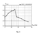
- FIG. 3 illustrates the variation of maximum lift coefficient with flap angle for baseline aerofoil SA-21, and the discontinuous change in the variation at flap angle of about 30° to 35°.
- FIG. 4 illustrates in plan view an air vehicle comprising wings based at least in part on two-element aerofoils according to at least one example of the presently disclosed subject matter.
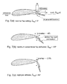
- FIG. 5 illustrates a two-element aerofoil according to one example of the presently disclosed subject matter.
- FIGS. 6( a ) to 6( e ) illustrate various modes of operation of the aerofoil of FIG. 5 corresponding to respective flap deflections.
- FIGS. 7( a ) to 7( c ) illustrate the axial overlap obtained with the aerofoil of FIG. 5 corresponding to flap deflections of 0°, +25°, +60°, respectively.
- FIGS. 8( a ) and 8( b ) illustrate, at Reynolds numbers of 0.3*10 6 and 0.5*10 6 , respectively, lift coefficient variations with angle of attack obtained with the aerofoil of FIG. 5 corresponding to flap deflections of 0°, +10°, +20°.
- FIGS. 9( a ) to 9( d ) illustrate pressure distributions obtained in wind tunnel tests with the aerofoil of FIG. 5 at a number of post-stall angles of attack, corresponding to flap deflection of 0° and Reynolds numbers of 0.3*10 6 .
- FIGS. 10( a ) to 10( d ) illustrate pressure distributions obtained in wind tunnel tests with the aerofoil of FIG. 5 at a number of post-stall angles of attack, corresponding to flap deflection of +20° and Reynolds numbers of 0.3*10 6 .
- FIGS. 11( a ) and 11( b ) illustrate hysteresis effect on lift coefficient variations with angle of attack obtained in wind tunnel tests with the aerofoil of FIG. 5 at flap deflection of 0° and Reynolds numbers of 0.3*10 6 .
- FIGS. 12( a ) and 12( b ) illustrate hysteresis effect on lift coefficient variations with angle of attack obtained in wind tunnel tests with the aerofoil of FIG. 5 at flap deflection of +20° and Reynolds numbers of 0.3*10 6 .
- FIG. 13 compares lift coefficient variations with angle of attack obtained in wind tunnel tests with the aerofoil of FIG. 5 at flap deflection of 0° and at flap deflection of +60°, at Reynolds numbers of 0.3*10 6 .
- FIGS. 14( a ) to 14( d ) illustrate pressure distributions obtained in wind tunnel tests with the aerofoil of FIG. 5 at a number of post-stall angles of attack, corresponding to flap deflection of +60° and Reynolds numbers of 0.3*10 6 .
- FIG. 15 compares axial overlap variation with flap deflection angle, obtained with the aerofoil of FIG. 5 and obtained with baseline aerofoil SA-21.
- FIG. 16 compares maximum lift coefficient variation with flap deflection angle, obtained with the aerofoil of FIG. 5 and obtained with baseline aerofoil SA-21.
- FIG. 17( a ) illustrates at Reynolds numbers of 0.5*10 6 , lift coefficient variations with angle of attack obtained with the aerofoil of FIG. 5 corresponding to flap deflections of 0°, +10°, +25°;
- FIG. 17( b ) illustrates drag coefficient variations with flap angle obtained with the aerofoil of FIG. 5 .
- FIG. 18 illustrates a simplified estimation of glide angle with Lift/Drag ratio.
- FIG. 19 illustrates the geometry and general dimensions of UAV AK-60.
- FIGS. 20( a ) and 20( b ) illustrate flight test results of angle of attack variation with time, and stall velocity variation with time, respectively, obtained with UAV AK-60.
- FIGS. 21( a ) to 21( d ) illustrate variations with time of angle or attack, glide angle, velocity, and rate of descent (ROD), respectively, at conditions of flap deflection angle +20°, elevator deflection angle ⁇ 12° and engine idle, obtained with flight test of the UAV AK-60.
- ROD rate of descent
- FIGS. 22( a ) to 22( d ) illustrate variations with time of angle or attack, glide angle, velocity, and rate of descent (ROD), respectively, at conditions of flap deflection angle +60°, elevator deflection angle ⁇ 12° and engine idle, obtained with flight test of the UAV AK-60.
- ROD rate of descent
- FIG. 23 schematically illustrates the wing lift coefficient variation with angle of attack for the UAV AK-60.
- FIG. 24 illustrates variations of lift coefficient and drag coefficient with flap deflection angle obtained in two-dimensional wind tunnel testing of aerofoil SA-MS/17MLS.
- FIG. 25 schematically illustrates various forces acting on an air vehicle during landing maneuver according to aspects of the presently disclosed subject matter
- FIG. 25( a ) schematically illustrates approximate balance of forces on the air vehicle of FIG. 25 .
- FIG. 26 illustrates the variation of the thrust lift force component, as a percentage of total thrust, with pitch angle ⁇ of the thrust vector to the horizontal H.
- FIG. 27 illustrates schematically various options for landing conditions with respect the wing lift coefficient variation with angle of attack for the UAV AK-60.
- FIG. 28 illustrates controllability limits for the UAV AK-60, in terms of variation of maximum lift coefficient with angle of attack.
- FIG. 29 illustrates spanload distributions of lift coefficient for an example of SA-MS wings.
- FIG. 30 illustrates longitudinal stability of the UAV AK-60, in terms of variation of maximum lift coefficient with function of pitching moment.
- a powered aircraft in particular a fixed wing powered aircraft is provided with high lift wings.
- a fixed-wing aircraft generally designated with reference numeral 1 , comprising a regular subsonic/transonic configuration, having a fuselage section 2 , main wings 10 (only the starboard wing (also referred to herein as a “wing half”) is illustrated in this figure), tailplane 3 , vertical stabilizers 4 , and a propulsion system 5 .
- the presently disclosed subject matter is also applicable, mutatis mutandis, to other types of aircraft, for example: subsonic/transonic aircraft having canards rather than a tailplane; general aviation aircraft, cruise missiles or other air delivered ordinance, and so on.
- subsonic/transonic aircraft having canards rather than a tailplane
- general aviation aircraft cruise missiles or other air delivered ordinance, and so on.
- the presently disclosed subject matter finds particular application in UAV aircraft, the presently disclosed subject matter can also be applied to manned aircraft, mutatis mutandis, in particular to general aviation, subsonic transport, naval aviation, guided or other weapons, and so on, for example.
- the air vehicle further comprises a control system comprising a controller (not shown) configured for operating the air vehicle during a landing maneuver as disclosed herein.
- the propulsion system 5 is a controllable propulsion system configured for providing a thrust T.
- this thrust can be produced directly from the engine as engine thrust—for example where the propulsion engine is a turbofan or turbojet.
- the propulsion engine drives one or more rotors, such as for example propellers or fans, the propulsion engine generates power that drives the rotor, rather than generate thrust directly, and the rotors each generate thrust aerodynamically as it turns in the air.
- the propulsion system 5 is configured for providing a controllably changeable level of thrust T, ranging from a minimum thrust T MIN at idle to a maximum thrust T MAX .
- the propulsion system 5 is in the form of a forward mounted single puller propeller, though in alternative variations of the example, the propulsion system can include more than one puller propellers and/or one or more than one pusher propellers and/or one or more of: turbojets, propfans, turboprop, turbofans, and so on, mounted on the wings and/or fuselage or elsewhere with respect to the air vehicle.
- turbojets propfans
- turboprop turbofans
- turbofans turboprop, turbofans, and so on
- the term “propeller” herein also refers to unducted fans, ducted fans, and other rotors that are configured for providing an aerodynamic propulsive thrust when driven by the propulsion engine.
- the direction of thrust T for forward flight generated by the propulsion system 5 i.e., the thrust vector TV
- the direction of thrust T for forward flight generated by the propulsion system 5 is fixed with respect to the air vehicle, and is generally correlated to the longitudinal axis LA of the air vehicle, typically the thrust vector TV being at an angle ⁇ to the longitudinal axis LA (in pitch), wherein angle ⁇ can be zero.
- the direction of thrust T is parallel to the longitudinal axis LA and passes through the center of gravity, or the direction of thrust T can be inclined by angle ⁇ within up to ⁇ 5° to the longitudinal axis LA in pitch, for example.
- the wing has a substantially trapezoidal plan shape, the leading edge 52 of the wing 10 being substantially rectilinear and having a substantially zero sweep angle, and the wing having a taper of between about 0.6 to about 1.0, between the root 24 and the tip 22 .
- the trailing edge 54 of the wing 10 is also substantially rectilinear and comprises a substantially negative sweep angle.
- the wing 10 can have a different plan form, for example: swept-back or swept forward, and/or with a different taper ratio (along the full wing, or different taper ratios for the inboard section and the outboard section), for example a zero taper ratio along the span of the wing 10 ; and/or having a different plan form, including curved leading edges and/or trailing edges such as an elliptical form, for example; and/or the inboard section and/or the outboard section can have a positive, negative or zero dihedral angle; and so on.
- a different taper ratio along the full wing, or different taper ratios for the inboard section and the outboard section
- the inboard section and/or the outboard section can have a positive, negative or zero dihedral angle; and so on.
- the wing 10 is configured for providing high lift mild stall characteristics. This feature enables the air vehicle 1 to land at low speeds, including a range of post-stall speeds at high angles of attack, exploiting the relatively high lift coefficient still available at post-stall.
- the wing 10 in this example is based on (i.e., the wing 10 comprises a plurality of aerofoil sections at least a portion of which each correspond to) a two-element mild stall slotted aerofoil 300 , also interchangeably referred to herein as SA-MS aerofoil or SA-MS aerofoil 300 , in particular exhibiting high lift mild stall characteristics.
- Aerofoil 300 comprises a first or primary element 32 (also referred to interchangeably herein as the “main body of the aerofoil”, or as the “main body”), and a pivotable second or secondary element 34 (also referred to interchangeably herein as the “flap” of the aerofoil, or as the flap).
- the primary element 32 comprises the leading edge 38 of the aerofoil, which coincides with the leading edge 52 of the wing 10 , and major portions 31 a , 33 a , of the suction surface 31 and pressure surface 33 thereof, respectively, and a trailing end 38 a , also referred to interchangeably herein as the trailing edge of the primary element 32 .
- the secondary element 34 comprises the trailing edge 39 of the aerofoil, which coincides with the trailing edge 54 of the wing 10 , and minor portion 31 b , 33 b , of the suction surface 31 and pressure surface 33 thereof, respectively.
- a slot 55 separates the leading end 35 of the secondary element 34 (also referred to interchangeably herein as the leading edge of the secondary element 34 ) from the trailing end 38 a of the primary element 32 .
- the slot 55 can have an axial width w at least 2% of the aerofoil chord C in a non-deflected position of the flap element.
- Reference line RL is a datum line conventionally defined with respect to the aerofoil 300 , and the angle of attack ⁇ of the aerofoil 300 , and deflection angle ⁇ of the secondary element 34 , are defined with respect to this datum line.
- the deflection angle ⁇ is also referred to interchangeably herein as flap deflection angle ⁇ or as flap angle ⁇ .
- airbrake mode
- the hinge point 59 of the secondary element 34 is fixed at an outwardly displaced position with respect to the lower (pressure) surface of the secondary element 34 .
- the airflow through slot 55 provides enhanced efficiency and linearity of the aerodynamic characteristics of the aerofoil as compared to a similar non-slotted aerofoil.
- a suitable actuation mechanism (not shown) is provided for actuating the secondary element 34 to adopt the range of deflection angles desired, including airbrake mode deflection angles.
- the secondary element 34 is formed as a slotted flap segment, having a slotted flap construction, comprising sub-elements 34 a and 34 b , rigidly connected to one another and separated by minor slot 37 , such that the secondary element 34 rotates about hinge point 59 as a rigid body.
- the slotted flap construction is configured for facilitating providing smooth lift characteristics at post-stall angles of attack at intermediate positive flap deflections with deflection angles ⁇ of about 15° to about 25°.
- the secondary element 34 is formed as a single continuous flap segment, without the minor slot.
- the secondary element 34 is spatially positioned with respect to the primary element 32 to provide a characteristic relationship between the longitudinal overlap M (between primary element 32 and the secondary element 34 ), and the deflection angle ⁇ of the secondary element 34 with respect to the primary element 32 .
- the longitudinal overlap M is unconventionally chosen to maximize the maximum lift coefficient that is obtained at deflection angles ⁇ that are significantly larger than the deflection angle ⁇ associated with maximum lift of the aerofoil, and in particular at deflection angles ⁇ associated with airbrake mode of the aerofoil.
- the secondary element 34 is deflected by a respective flap deflection angle corresponding to a design airbrake deflection angle wherein to generate an airbrake drag.
- the flap angle ⁇ is large, and generates significantly more drag than at flap angles associated with maximum lift coefficient of the aerofoil in which flow on the flap segment is attached or almost attached (while concurrently the maximum lift coefficient can remain almost constant).
- the flap angle ⁇ can be more than 40°, or more than 50°, or more than 55°, or 60° or more than 60°.
- the respective drag coefficient is at least 150% of the value at flap angle ⁇ of 30°, and the respective drag coefficient at these airbrake mode flap deflection angles ⁇ can be greater than 0.15, or greater than 0.2, or greater than 0.3, for example.
- the flow over the secondary element is fully detached.
- the longitudinal overlap M thus chosen retains a high maximum lift for the aerofoil 300 . Furthermore, and as will become clearer below, and the longitudinal overlap M thus chosen also allows the aerofoil 300 to produce mild stall characteristics. In turn, this allows for the integration of the secondary element 34 as an airbrake with a mild stall wing 10 and for flight of the aircraft 1 at post stall angles of attack, thereby retaining the plateau of high lift coefficient (associated with mild stall) with the secondary element 34 deployed as an airbrake.
- the longitudinal overlap M is about +4% of the chord, whereas at a deflection angle ⁇ of about 60°, for example, associated with airbrake mode, the longitudinal overlap M is about ⁇ 0.5% of the chord.
- the longitudinal overlap M is unconventionally chosen to be larger, for example 1% or 2% or 3% or more than 3% of the chord larger, at any given flap angle, than would be the case if the longitudinal overlap M were conventionally chosen.
- the longitudinal overlap M can be optimized to be within the range +2% to ⁇ 0.5% (or to be within the range +1% to ⁇ 0.5%) at deflection angles ⁇ wherein the flap operates as an air brake—for example at airbrake deflection angle ⁇ of 45° or more, or at airbrake deflection angle ⁇ of 50° or more, or at airbrake deflection angle ⁇ of 55° or more, or at airbrake deflection angle ⁇ of 60° or more, or at airbrake deflection angle ⁇ of 65° or more, or at airbrake deflection angle ⁇ of 70° or more, or at airbrake deflection angle ⁇ of 75° or more, or at airbrake deflection angle ⁇ of 80° or more.
- the numerical value for the flap angle ⁇ and the longitudinal overlap M can be chosen to provide the desired level of drag (see FIG. 17( b ) ) and desired maximum lift coefficient and post stall lift characteristics.
- the gap N between primary element 32 and the secondary element 34 can be set in a conventional manner, for example as set forth in FIG. 1 , and for example kept at between about 1% and about 2% of the chord.
- the location of the hinge point 59 is chosen to provide the desired longitudinal overlap M (and optionally also the desired gap N) as a function of the flap angle ⁇ , and further, minimizes hinge moments, optimizes flap stability (providing the flap neutral point downstream of the hinge point 59 ), and complies with the conventional requirements of flap actuator failure case.
- the secondary element 34 can comprise control surfaces such as ailerons, flaps and so on, that are pivotable with respect to the secondary element 34 .
- the wing half 10 can optionally comprise a number of span-wise wing sections, for example serially adjoining sections 10 a , 10 b , 10 c and 10 d , between the tip 22 and root 24 , in which one or more wing section the secondary element 34 is configured to perform as an air brake, while in one or more other wing section the secondary element 34 can be configured as a rigid non-movable element, or to operate within a narrower flap angle range, for example up to 30° only, thereby not operating as an airbrake, for example.
- section 10 a is configured with an aileron.
- the span of the respective one or more sections 10 a , 10 b , 10 c and 10 d that include the airbrake can be maximized.
- such an aerofoil design for aerofoil 300 can include any suitable thickness-to-chord ratio (t/c) max , camber distribution, and thickness distribution.
- the leading edge 38 of the aerofoil 300 can also be relatively blunt or rounded, having a low curvature leading edge radius, and aft portion of the aerofoil can also be cambered.
- the aerofoil 300 further comprises a highly cambered aft portion of primary element 32 , this aft portion being referred to herein as a mild-stall ramp section, or MS-ramp 154 .
- the profile of the MS ramp 154 is shaped for a particular design Reynolds number, such as to produce a slowly creeping trailing edge separation at post-stall angles of attack.
- the MS ramp 154 is configured for initiating mildly separated flow at stall angles of attack, for example at about 10°.
- the separated region on the MS-ramp 154 at post stall angles of attack continues to grow slowly, but does not induce full separation over the primary element 32 of the two-element aerofoil 300 , and enables a relatively high level of lift to be maintained at the post-stall angles of attack.
- Controllable development of the separated region on the MS-ramp 154 together with rounded pressure distributions at the leading edge 38 , which can be obtained with a relatively blunt or rounded leading edge, having a low curvature leading edge radius, provide mild stall characteristics at the level of lift that is generally generated with high-lift, two-element aerofoils.
- the upper suction surface 31 of the SA-MS aerofoil section includes portions of the downstream suction surface having a local curvature (1/r local ) that can increase, and/or that can remain substantially constant, i.e., where the local curvature does not substantially decrease, along the chord towards the trailing portion 38 a of the primary element 32 , beginning at an intermediate portion of the suction surface 31 a thereof.
- the MS-ramp 154 is downstream of an upstream portion 152 of suction surface 31 a , in which the local curvature is reducing along the chord length.
- the rate of change of curvature along the suction surface 31 from the leading edge 38 to trailing portion 38 a can be positive in some variations of this example, or zero in other variations of this example.
- the point 153 on the suction surface 31 a along the chord at which the curvature stops decreasing, i.e., the transition between portions 152 and 154 can be located at any suitable location.
- point 153 can be at any point between 15% and 25%, or at 30%, or at 40%, or at 45%, or at 50%, or at any point between about 30% and about 50%, or greater than 50% of the local chord (i.e., the chord of the primary element 32 ).
- the local curvature can be constant or increasing up to about 80%, 90%, 95% or more of the local chord.
- the aerofoil 300 maintains a stall plateau for angle of attack range of at least 7° where the lift coefficient C l is within up to about 5% of maximum C l .
- the MS ramp 154 can have a geometry that is dependent on the design Reynolds number for the aerofoil. For example, and without being bound to theory, inventors consider that the higher the design Reynolds number, the larger the local curvature of the MS-ramp 154 and the larger the longitudinal extent of the MS-ramp 154 over the major portions 31 a of the suction surface 31 (of primary element 32 ), and conversely, the lower the design Reynolds number, the lower the local curvature of the MS ramp and the lower the longitudinal extent of the MS-ramp 154 over the major portions 31 a of the suction surface 31 (of primary element 32 ).
- the larger curvature MS-ramp that can be provided for a high design Reynolds number also results in mild stall when the flow conditions are consistent with low Reynolds number, but at an additional drag penalty.
- the design Reynolds number for a two element aerofoil can be between about 0.3*10 6 to about 2.0*10 6 .
- rounded pressure distributions at the forward portion of the aerofoil prevent premature development of suction peak and delay a fast progress of separation at higher angles of attack; eventually, development of suction peak at high angles of attack accelerates the separation process at the aft portion of the main body, producing a very gradual loss of lift with increasing angles of attack.
- aerofoil SA-MS/17MLS (corresponding to aerofoil 300 ) does not show signs of hysteresis phenomena up to very high post-stall angles of attack, greater than about 32°.
- the lift coefficient obtained with aerofoil SA-MS/17MLS (corresponding to aerofoil 300 ) is not sensitive to the direction in which the angle of attack is changing. In other words, increasing the angle of attack to about 30°, and then decreasing the angle of attack provides the same variation of lift coefficients with angle of attack. However, at an angle of attack of about 34°, there is a change, and lower lift coefficients are obtained at angles of attack between 34° and about 12° as the angle of attack is reduced, as compared with the corresponding lift coefficients obtained at similar angles of attack but as the angle of attack is increased.
- the hysteresis behavior thus appears to start at the relatively large angle of attack of about 34°, and this allows safe operation of the air vehicle at high post-stall angles of attack up to a little under 34°, for example up to 32° or 33°. In practical terms, for UAV's or other aircraft, this corresponds to effectively eliminating hysteresis phenomena up to relatively high post stall angles of attack.
- aerofoil SA-MS/17-MLS corresponding to aerofoil 300
- aerofoil 300 including the airbrake mode thereof, is suitable for integration with high-lift, mild-stall wing, allowing safe operation of an air vehicle, such as for example a UAV, at post-stall angles of attack and as will become clearer below also allows for providing relatively steep glides angles at approach to landing at reduced airspeeds.
- aerofoil SA-MS/17MLS (corresponding to aerofoil 300 ) can be compared with the geometry of a conventional baseline slotted aerofoil of the same thickness ratio, and denoted herein as aerofoil SA-21, illustrated in FIGS. 2( a ) and 2( b ) , and while otherwise being similar to aerofoil SA-MS/17MLS, the baseline aerofoil SA-21 does not comprise an MS ramp (nor is configured to provide mild stall characteristics), and includes a conventional longitudinal overlap and a conventional gap, based on conventional optimization characterized by FIG. 1 .
- FIG. 15 shows the geometrical variation of longitudinal overlap with deflection angle ⁇ , for a range of deflection angle ⁇ from 0° to 80°, obtained for aerofoil SA-MS/17MLS (corresponding to aerofoil 300 ). While not shown, the longitudinal overlap provided by aerofoil SA-MS/17MLS is greater than that of baseline aerofoil SA-21 by about 2% of the chord, for a range of deflection angle ⁇ from 0° to 40°, thereafter this difference increasing to with deflection angle ⁇ to about 3% of the chord at deflection angle ⁇ of 80°.
- FIG. 16 compares the variation of maximum lift coefficient C lmax with deflection angle ⁇ , for a range of deflection angle ⁇ from 0° to 80°, obtained for aerofoil SA-MS/17MLS (corresponding to aerofoil 300 ). This figure further compares this variation, with the corresponding variation of maximum lift coefficient C lmax with deflection angle ⁇ , obtained for baseline aerofoil SA-21.
- the aerofoil SA-MS/17MLS (corresponding to aerofoil 300 ) provides a generally constant maximum lift variation (within a band of lift coefficient C l between about 2.3 and about 2.55, i.e., a variation of about ⁇ 5% or ⁇ 6% of the mean value of maximum lift coefficient) with deflection angle ⁇ , even at large flap deflections of 60° or 80°.
- the inventors consider that the concept of providing longitudinal overlap according to the presently disclosed subject matter is particularly suitable for integration with high-lift, mild-stall wings, which are configured for providing mild stall characteristics i.e., a plateau of lift coefficients at extended range of post-stall angles of attack.
- V flight >1.2 V stall and a corresponding lift coefficient safety margin constraint on the operation of the air vehicle, in which the lift coefficient of the wings of the air vehicle has to remain below the maximum lift coefficient by a factor of 1/1.44 (or must remain at under 70% of the maximum lift coefficient), i.e., C L flight ⁇ C Lmax /1.44.
- the high-lift mild stall characteristics of the aerofoils allow elimination of this speed safety margin and support safe flight of the aircraft at post-stall angles of attack maintaining high levels of lift.
- the respective aerofoil is not configured for providing high lift mild stall characteristics or for providing mild stall characteristics, though the respective aerofoil is otherwise configured as a two element slotted aerofoil, mutatis mutandis.
- the respective secondary element of such an aerofoil, pivotable about a fixed hinge joint and having a longitudinal overlap and gap as disclosed herein for aerofoil 300 will also enable the respective secondary element to operate in airbrake mode, and without being bound to theory inventors consider that such a configuration can help in moderating stall characteristics at high flap deflection angles corresponding to airbrake mode.
- the secondary element of the aerofoil provides a very high level of parasitic drag when in airbrake mode, as illustrated in FIG. 17( b ) , allowing approach to landing of an aircraft, for example a UAV, at reduced airspeeds at post-stall angles of attack with increased glide angles. This is not generally possible for high-lift, mild-stall wing with a conventional airbrake design because of the loss of lift at high deflection angles, and the resulting inability to provide safe flight at post-stall angles of attack.
- the slotted aerofoil including longitudinal overlap provides a particularly efficient airbrake for operation at approach to landing.
- L is the lift force and D is the drag force acting on the air vehicle at approach to landing. It is to be noted that, conventionally, glide angles below the horizon are considered negative, while glide angles above the horizon, i.e., climb angles, are considered positive.
- FIG. 18 illustrates the variation of glide angle ⁇ with lift-to-drag ratio (L/D).
- high (negative) values of glide angle ⁇ can be provided in airbrake mode, for example in the range of between ⁇ 3° to about ⁇ 15°, for example in the range of between ⁇ 10° to about ⁇ 15°, for example ⁇ 10°, or ⁇ 11° or ⁇ 12° or ⁇ 13° or ⁇ 14° or ⁇ 15° or numerically less than ⁇ 15°, with corresponding flap angles.
- glide angle ⁇ can be provided in the range ⁇ 10° to ⁇ 15°, for example glide angle ⁇ can be ⁇ 10°, or ⁇ 11° or ⁇ 12° or ⁇ 13° or ⁇ 14° or ⁇ 15°, and correspond to a flap deflection angle ⁇ of about +60°, for example, in airbrake mode.
- Maximizing the modulus of glide angle ⁇ can minimize exposure time of the air vehicle during landing. This can be of particular use in maritime applications, for example, wherein exposure to gusts etc. can be minimized when landing on a sea platform, such as an aircraft carrier, for example, particularly on rough seas.
- the ability to provide large (negative) glide angles ⁇ can also be useful where tall obstacles are located in the vicinity or perimeter of the landing site for example.
- the aerofoil 300 is configured to generate large values of drag concurrently with high lift (which provides low landing velocity) in airbrake mode—the high drag thus compensates for the increased lift at landing, to maintain low values of the lift-to-drag ratio (L/D), and thus provide high absolute values of (negative) glide angle ⁇ .
- the pivotable second or secondary element 34 capable of operating in the aforesaid airbrake mode, is referred to as high lift-high drag airbrake.
- the air vehicle 1 during a landing maneuver, adopts a relatively high angle of attack ⁇ , which concurrently provides a thrust vector TV having a significant vertical thrust component TL that contributes to the lift force on the air vehicle 1 .
- the landing maneuver can include approach to landing and/or landing of the air vehicle 1 .
- the air vehicle 1 is following a glide path indicated at FP during a landing maneuver, the glide path being at glide angle ⁇ to the horizontal H (i.e., to the Earth horizon, and below the Earth horizon), while the air vehicle 1 (for example, the longitudinal axis LA of the air vehicle 1 ) is at an angle of attack ⁇ .
- glide angles ⁇ below the horizon are defined as having negative values.
- the aerodynamic lift force L generated by the wings is orthogonal to the flight path FP
- the drag force generated by the air vehicle is parallel to the flight path FP
- the weight of the air vehicle acts orthogonal to the horizon H.
- the thrust vector TV of the thrust T is at angle ⁇ to the horizontal H.
- the thrust vector TV is aligned with the longitudinal axis LA, thus angle ⁇ is zero, and thus angle ⁇ ′ equals angle ⁇ .
- angle ⁇ can be positive or negative, and thus the longitudinal axis LA can be at a greater or less pitch angle ⁇ ′ as compared with the angle ⁇ of the thrust vector TV to the horizontal.
- the thrust vector TV resolves the thrust T into a thrust lift force component TL orthogonal to the horizontal H, and a forward thrust component TH parallel to the horizontal H.
- FIG. 26 illustrates the variation of thrust lift force component TL (as a percentage of total thrust T) with pitch angle ⁇ .
- glide angles ⁇ can vary between about ⁇ 4° and about ⁇ 1.5° during landing, for example—see FIG. 18 —and thus pitch angle ⁇ can be very close to the angle of attack ⁇ .
- pitch angle ⁇ can be very close to the angle of attack ⁇ .
- providing a pitch angle ⁇ of 20° provides a thrust lift force component TL of about 34% of the thrust T generated by the propulsion system 5
- a pitch angle ⁇ of 30° provides a thrust lift force component TL of about 50% of the thrust T. It is evident that according to this aspect of the presently disclosed subject matter, the thrust T of the propulsion system 5 can significantly contribute to the total lift force L TOTAL acting on the air vehicle during landing.
- the thrust contribution to lift provided by the thrust lift force component TL by virtue of providing a high pitch angle ⁇ does not come as a detriment to the aerodynamic lift force L provided by the wings.
- the pitch angle ⁇ is chosen to correspond to the angle of attack ⁇ (of the air vehicle 1 ) in the post-stall regime of the mild stall wings, where the lift coefficient C L , post stall, remains high as angle of attack is increased post stall.
- the lift coefficient in the post-stall regime remains high at about 2.5 ⁇ 0.1 for a range of angle of attack between 10° and 20°.
- the glide angle is numerically increased (in the negative sense) by vastly increasing the drag generated at landing, this being accomplished by operating the air vehicle in the aforesaid airbrake mode.
- high levels of absolute value of thrust T are maintained, providing a significant contribution of thrust lift force component TL to the lift of the air vehicle 1 , while not increasing the speed of the air vehicle at landing. Rather, the airspeed of the air vehicle can be actually reduced.
- This is achieved, according to the aspect of the presently disclosed subject matter, by concurrently deploying (in at least one example) the air brakes at high flap deflection angles corresponding to airbrake mode, thereby providing high levels of drag while maintaining the lift coefficient relatively constant.
- the air brakes are used in airbrake mode to increase the drag, while not substantially affecting lift of the wings.
- the air vehicle is configured such that the total drag exceeds the thrust generated during landing, the difference between the drag and the thrust defining the glide angles (see relationship (B) above) which are lower relative to conventional type of landing (at similar drag levels).
- the thrust contribution to lift allows operation of the air vehicle at airspeeds (V flight ) that are below the stall speed of the air vehicle (V stall ), for example airspeeds (V flight ) of between 90% and 95% of the stall speed V stall , at high-post stall angles of attack. It is also to be noted that during landing, the weight of air vehicle is supported by reduced lift force (due to reduced air speed at landing) plus thrust contribution to lift (generated by the engine) TL, as illustrated in FIG. 25 and FIG. 25( a ) .
- the method of operation of the air vehicle at landing allows operation of the air vehicle at high post-stall angles of attack concurrently with airspeeds (V flight ) between 90% and 95% of V stall , when V stall is an average airspeed corresponding to the post-stall plateau of lift coefficients corresponding to the mild stall characteristic of the wings of the air vehicle 1 .
- the level of thrust T to be set relatively high (and much higher than idle, for example), thereby allowing for a significant contribution of thrust lift force component TL to the lift of the air vehicle 1 , while the additional forward thrust component TH is offset by the increased drag generated by the air brakes.
- the thrust contribution to lift can be quite moderate (for example with the engine operating at only partial thrust), but can still be significant as it enables a reduction of air vehicle kinetic energy, and furthermore this effect can be increased by the additional speed reduction that can be obtained due to high lift effect and elimination of speed safety margin.
- the air vehicle can be decelerated and operated at relatively low airspeeds during landing, while at the same time generating relatively large lift force via the thrust lift force component TL.
- the mild stall characteristic of the wings of the air vehicle 1 further allows the stall margin to be exploited, and allow the air vehicle 1 to operate at even slower speeds during the landing maneuver.
- this allows for a greater (negative) glide angle ⁇ to be used for the landing maneuver, allowing a shorter landing distance, facilitating avoidance of ground obstacles and/or providing accuracy of touch down location in ground effect.
- the relative large levels of drag that can be generated by the operation of the air brakes in airbrake mode allows for such relatively large (negative) glide angle ⁇ (see relationships (A) and (B) above).
- the level of thrust T during a landing maneuver can be any one of the following percentages of the nominal maximum thrust T MAX : 5%; 10%; 15%; 20%; 25%, 30%; 35%, 40%; 45%; 50%; 55%; 60%; 65%; 70%; 75%; 80%; 85%; 90%; 95%.
- the level of thrust T during a landing maneuver can be within any one of the following ranges of percentages of the nominal maximum thrust T MAX : 1% to 5% and/or 5% to 10% and/or 10% to 15% and/or 15% to 20% and/or 25% to 30% and/or 30% to 35% and/or 35% to 40% and/or 40% to 45% and/or 45% to 50% and/or 50% to 55% and/or 55% to 60% and/or 60% to 65% and/or 65% to 70% and/or 70% to 75% and/or 75% to 80% and/or 80% to 85% and/or 85% to 90% and/or 90% to 95 and/or 95% to 100%.
- drag inducing devices can be employed which selectively induce drag at landing while not substantially affecting the flow over the wings.
- drag inducing devices do not significantly affect the wing aerodynamics including lift coefficient.
- Such drag inducing devices can include, for example, deployable airbrakes on the fuselage, deployable parachutes, and so on.
- various landing methods can be employed by the air vehicle 1 , and four such methods, denoted herein as landing modes A, B, C and D, are discussed below.
- the air vehicle lands in a conventional manner, complying with the standard speed safety margin in which the velocity of the air vehicle is at least 20% greater than the stall speed (i.e., V flight >1.2V stall ).
- V flight i.e., V flight >1.2V stall
- the angle of attack of the wings is relatively low, as is the air vehicle coefficient of lift C L .
- the high lift-high drag airbrake may provide improved glide angles, there is no significant advantage provided by the aforesaid high lift-high drag airbrake, i.e., the potential high drag and high lift characteristics of the airbrake are not generally realized under these conditions.
- the air vehicle In this landing mode, the air vehicle lands in a non-conventional manner, eliminating the speed safety margin of V flight >1.2V stall , and the propulsion system operates at idle thrust.
- the angle of attack of the wings is relatively high, and the air vehicle coefficient of lift C L is at a maximum, at stall.
- the high lift-high drag airbrake provide improved glide angles, as well as increased parasitic drag, providing greater rate of descent.
- operation of the airbrake in airbrake mode can ensure flight safety at stall conditions and provides improved glide angles as compared with landing mode A.
- thrust is maintained at idle, in view of the degradation of (negative) glide angle at approach to landing, minimizing any potential lift benefits of increasing engine thrust.
- landing mode C In this landing mode, represented at “C” in FIG. 27 , the air vehicle lands in a non-conventional manner, eliminating the speed safety margin of V flight >1.2V stall , and the propulsion system operates at idle thrust, in a similar manner to landing mode B.
- the angle of attack is much greater than in landing mode B, but still within the angle of attack range in the plateau of lift coefficients, marked at P in FIG. 27 .
- the increased angle of attack increases the effect of the high lift-high drag airbrake, providing increased parasitic drag, improved rate of descent as compared with landing mode B.
- the mild stall high lift nature of the wings allows operation of the wings for an extended range of angles of attack.
- landing mode C becomes in general preferable to landing mode B.
- Operation of the air vehicle at such angles of attack corresponding to landing mode B can be accomplished, for example, by providing and maintaining a corresponding negative elevator setting to the air vehicle.
- landing mode D In this landing mode, represented at “D” in FIG. 27 , the air vehicle lands in a more non-conventional manner than at “C”, eliminating the speed safety margin of V flight >1.2V stall , and the propulsion system operating at a thrust that is significantly above idle thrust.
- the angle of attack is greater than in landing mode C, being at the higher end of the angle of attack range in the plateau of lift coefficients P. At these angles of attack, the thrust contribution to lift is significant, allowing for further reduction in airspeed.
- V stall a new reduced level of stall speed (V stall ) is established (as compared with landing mode A, for example), and at the reduced dynamic pressure corresponding new stall speed, the weight of the air vehicle is supported only partially by the lift force, the rest of the weight being supported by the thrust contribution to lift.
- the resulting slipstream effect can also reduce the airspeed further.
- the propeller generates a higher dynamic pressure (i.e. higher than that due to the forward speed of the air vehicle) over the inboard portions of the wings and fuselage, providing additional lift and thus allowing for reducing airspeed further.
- the high drag generated by the high lift-high drag airbrake not only provides increased parasitic drag as compared with landing mode C, it also compensates for the forward thrust component of the increased thrust, thereby enabling reduced landing speed in spite of the thrust being higher than idle.
- landing mode D provides the minimum possible landing speed at touchdown, as compared with landing modes A, B or C.
- reduced airspeed (even below the stall airspeed, for example 90% to 95% of V stall ) can be achieved because of the thrust contribution to lift, while the reduced dynamic pressure corresponding to such reduced airspeeds the physical lift generated by the air vehicle is insufficient to support the weight of air vehicle, the deficiency in aerodynamic lift is made up by the thrust contribution to lift.
- landing mode D there is a decrease of (negative) glide angle as compared with landing mode C.
- landing mode D high levels of drag at high post-stall angles of attack and at airbrake mode compensate for the forward thrust resulting from operating the engine at thrust levels higher than idle, and as shown above the difference between the drag and forward thrust can be sufficient to provide minimum required glide angles (of between ⁇ 3° and ⁇ 4°, for example).
- a UAV designated AK-60
- AK-60 was developed by the present assignee as a fully instrumented Wing Technology Flight Demonstrator, with the specific purpose to evaluate in-flight high-lift, mild-stall wings at domain of post-stall angles of attack and specifically the option of landing at stall at reduced airspeeds with increased glide angles employing the feature of the airbrake concept according to the above aspects of the presently disclosed subject matter.
- the UAV AK-60 has a conventional wing-body-tail arrangement that is shown in FIG. 19 , which also shows various overall dimensions of this UAV.
- the main wings of the UAV AK-60 configuration were high-lift, mild-stall wings, comprising airfoil sections corresponding to airfoil SA-MS/17-MLS (see FIGS. 5 to 7 ( c )), which included the feature of the airbrake concept according to the above aspects of the presently disclosed subject matter.
- the first one was of a primary nature—demonstration of advantages of landing at stall at reduced airspeeds and with relatively steep glide angles via implementation of innovative design concepts (high-lift, mild-stall wing, the feature of the airbrake concept and thrust contribution to lift according to the above aspects of the presently disclosed subject matter).
- the second one was of supplementary nature—verification of flight safety and validation of acceptable flying qualities up to high post-stall angles of attack.
- the concept of landing at stall was evaluated in a number of flight tests of UAV AK-60 with a slotted mild stall wing and including the feature of the airbrake concept according to the above aspects of the presently disclosed subject matter.
- Most of flight testing was performed with a slotted mild stall wing based on airfoil SA-MS/17MLS, incorporating the feature of the airbrake concept according to the above aspects of the presently disclosed subject matter.
- a limited number of flight tests were performed with a slotted mild stall wing that was based on a single element high lift airfoil (as disclosed in U.S. Pat. No. 7,992,827, “Wings for Aircraft”, Ref. 6).
- the thrust contribution to lift concept, particularly together with airbrake concept, supports a corresponding innovative approach of UAV landing, in which the UAV lands with reduced airspeeds and steep glide angles.
- the thrust contribution to lift concept, particularly together with airbrake concept, allows for providing a method of operation of air vehicles, such as for example tactical UAVs, at approach to landing and landing, and can integrate one or more of the following features (see FIG. 23 ):
- the combination of features of high-lift, mild-stall wing, the airbrake concept, and thrust contribution to lift provides novel methods of operation of air vehicles, in particular UAV, by operating the air vehicle at very high post-stall angles of attack and maintaining engine power such as to generate thrust much higher than at engine idle conditions, thereby automatically providing a thrust contribution to lift.
- air vehicles in particular UAV
- features of at least some such methods of operation can include landing at reduced airspeeds and relatively steep glide angles, which in turn helps to achieve short landing distance and provides the capability to avoid ground obstacles at the final stages of approach to landing.
- the airbrake concept according to at least some other of the above aspects of the presently disclosed subject matter can be integrated in other types of slotted wings which are not necessarily mild stall or high lift mild stall wings.
- this allows for providing a method of operation of air vehicles, such as for example tactical UAVs, at approach to landing that provides high drag when the airbrake is deployed, without comprising lift, thereby allowing for relatively steep glide angles, although in such cases the standard speed safety margin V flight >1.2V stall is maintained.
- the SA-MS aerofoil sections for the wing 10 can be designed in any suitable manner, for example based on the methods as disclosed in U.S. Pat. No. 8,109,473 or 7,992,827, mutatis mutandis, these references being incorporated herein in their entirety, and incorporating the axial overlap as disclosed herein.
- a known slotted aerofoil design that can be close in characteristics to that required, for example camber, thickness to chord ratio, and so on.
- a baseline aerofoil can be designed using known methods. Then, the baseline aerofoil contour can be modified to provide a relatively blunt leading edge to obtain high lift, and a suction surface that is cambered and/or has a thickness distribution such as to provide slowly creeping trailing edge separation.
- the profile of a downstream portion of the suction surface of the leading element of the slotted aerofoil is changed so as to provide a local curvature (1/r local ) that in some parts thereof increases, and/or in other parts thereof remains substantially constant; at the same time, the longitudinal overlap between the primary element and the secondary element is chosen according to the presently disclosed subject matter.
- CFD methods can be used, for example, to test the aerofoil, which can then be modified further, and again tested to determine whether the modification is providing the required aerodynamic effect. A number of such trial and error iterations can be carried out until a suitable profile for the aerofoil, providing the required characteristics, is achieved.
- the full span of the half-wing 10 can comprise the same aerofoil profile (scaled if necessary according to the aspect ratio, for example), save possibly for aerodynamic or structural features such as booms, wing tip winglets and the like, for example, in a similar manner to the configuration of regular slotted aerofoils along the wing span of the IAI Heron, for example, mutatis mutandis.
- different portions of the half-wing 10 can comprise different aerofoil profiles, suitably blended along the span or optionally comprising a flow separation plate or the like separating the various wing portions.
Landscapes
- Engineering & Computer Science (AREA)
- Aviation & Aerospace Engineering (AREA)
- Mechanical Engineering (AREA)
- Remote Sensing (AREA)
- Radar, Positioning & Navigation (AREA)
- Physics & Mathematics (AREA)
- General Physics & Mathematics (AREA)
- Automation & Control Theory (AREA)
- Structures Of Non-Positive Displacement Pumps (AREA)
- Control Of Vehicle Engines Or Engines For Specific Uses (AREA)
Abstract
Description
- 1. U.S. Pat. No. 8,109,473
- 2. Nagel, A., and Shepshelovich, M., “Development of High-Lift UAV Wings”, 24th AIAA Applied Aerodynamics Conference, San Francisco, Calif., 5-8 Jun. 2006.
- 3. Shepshelovich, M., “The Progress in Development of UAV Wings”, International Conference ICAUV-2009, Bangalore, India, 2009
- 4. Steinbuch, M., Marcus, B., Shepshelovich, M., “Development of UAV Wings—Subsonic Designs”, 41st Aerospace Sciences Meeting, Reno, Nev., 6-9 Jan. 2003.
- 5. McCormick, B. W., “Aerodynamics Aeronautics and Flight Mechanics”, John Wiley & Sons, book, 2nd edition, 1995.
- 6. U.S. Pat. No. 7,992,827
- 7. Abbott, I. H. and Von Doenhoff, A. E., “Theory of Wing Sections”, Dover Publication, book, 1959.
- 8. FR 53,254
- 9. GB 521,190
V stall=(2W/(ρ*C L max *S w))0.5
-
- during a landing maneuver, causing the air vehicle to attain an angle of attack corresponding to said post-stall regime; and
- during said landing maneuver, concurrently generating a thrust level of said thrust greater than said idle thrust to provide a thrust vector having a thrust lift force component at landing.
α=θ−γ
TL=T*sin θ
TH=T*cos θ
γ=(D−T)/L
-
- causing the air vehicle to attain an angle of attack corresponding to said post-stall regime during a landing maneuver; and
- concurrently generating during said landing maneuver, a thrust level of said thrust greater than said idle thrust to provide a thrust vector having a thrust lift force component at landing.
-
- deflecting the secondary element to said design airbrake deflection angle to provide said airbrake drag;
- reducing airspeed of the air vehicle to values corresponding to the level of maximum lift.
-
- CL 1.5/CD—aircraft endurance factor α—angle of attack
- CL—aircraft lift coefficient δail—aileron deflection
- Cd—aerofoil drag coefficient δ—flap deflection
- Cl—aerofoil lift coefficient Clmax—wing maximum lift
- Clmax—aerofoil maximum lift AR—aspect ratio
- Cm—aerofoil pitching moment CFD—computational fluid dynamics
- Cp—pressure coefficient IAI—Israel Aircraft Industries
- CD 0—zero lift drag NLF—natural laminar flow
- e—spanload efficiency MS—mild stall
- Re—Reynolds number SA—slotted aerofoil
- t/c—thickness ratio UAV—unmanned air vehicle
- x/c—chord fraction W—Weight
- TV—thrust vector (i.e., direction θ—pitch angle of the thrust of thrust) vector to the horizontal
- TH—forward thrust component H—horizontal or horizon
- TL—thrust lift force component T—thrust
γ=1/(L/D) (A)
(i.e., glide angle γ=D/L)
α=θ−γ
TL=T*sin θ
TH=T*cos θ
L TOTAL ˜L+T*sin θ
Or, more precisely:
L TOTAL= L*cos γ+T*sin θ
T*cos θ˜D
Or, more precisely:
T*cos θ=D*cos γ−L*sin γ
γ=(D−T)/L (B)
-
- large wing area/low wing loading for providing reduced airspeeds at all stages of the flight;
- implementation of high-lift, mild-stall SA-MS aerofoil-based wing and elimination of speed safety margin Vflight>1.2Vstall;
- the use of high-lift devices for producing high maximum lift (actually maximum usable lift because of elimination of speed safety margin);
- implementation of the feature of the airbrake concept according to the above aspects of the presently disclosed subject matter for providing increased glide angles at approach to landing without penalizing lift and maximum lift characteristics at post-stall angles of attack and retaining reduced airspeeds with deployed airbrake;
- exploiting thrust contribution to lift at high post-stall angles of attack for a further reduction of airspeed at approach to landing, the forward thrust thereby generated being counterbalanced by airbrake drag for retaining acceptable glide angles.
-
- Flight at post-stall angle of attack (α˜15°)
- Characteristics of the flight at post-stall angles of attack of about 15° are shown in
FIG. 20(a) andFIG. 20(b) . As anticipated by the inventors, the average airspeed at post-stall was close to stalling speed of Vstall˜30 kts.
- Characteristics of the flight at post-stall angles of attack of about 15° are shown in
- Landing at stall
- Approach to landing at post-stall angles of attack is shown in
FIGS. 21(a) to 21(d) , for flap deflection angle δflap=+20°, andFIGS. 22(a) to 22(d) , for flap deflection angle corresponding to airbrake mode, δairbrake=+60°. For both cases the approach to landing was performed at a respective angle of attack corresponding to the middle of post stall plateau range of lift coefficients (because of the nose-down tendency of the air vehicle at high angle of attack), with an elevator deflection angle δel of −12°, and with the engine setting of the air vehicle at idle. Comparison ofFIG. 21(b) withFIG. 22(b) clearly show a 50% numerical increase in the glide angle γ, which increased (in a negative angular direction) from −8° at flap deflection angle of +20°, to −12° at flap deflection angle of +60°. Similarly, comparison ofFIG. 21(d) withFIG. 22(d) clearly show an 18% increase in the rate of descent (ROD), which increased from 490 ft/sec at flap deflection angle of +20°, to 580 ft/sec at flap deflection angle of +60°. These improvements in glide angle and rate of descent were achieved without affecting the approach airspeed of the air vehicle, and inventors suggest that this indicates that the incorporation of the feature of the airbrake concept according to the above aspects of the presently disclosed subject matter to high lift mild stall wings does not distort the variation of lift coefficient with angle of attack at the post-stall plateau of lift coefficients of mild stall wings, and moreover retains the maximum lift coefficient of the baseline wing configuration at conventional flap deflection angles of about +20°. Thus, the feature of the airbrake concept according to the above aspects of the presently disclosed subject matter did not adversely affect the airspeed of the air vehicle, and improved significantly the glide angles and rate of descent of the air vehicle.
- Approach to landing at post-stall angles of attack is shown in
- Flight at post-stall angle of attack (α˜15°)
-
- the air vehicle flying at post-stall angles of attack should be fully controllable in all stability planes. Theoretical stall simulations were performed, and this helped to establish controllability limits on conservative basis that are shown in
FIG. 28 . It was predicted that up to α=20°, no degradation of longitudinal and roll control are to be expected, ensuring flight safety at post-stall angles of attack. The actual flight testing was performed up to α=25°, indicating fully controllable flight at high post-stall angles of attack - improved controllability in the roll plane at post-stall angles of attack was achieved by combination of taper ratio and twist that produced a gradual decrease of the local loading across the span of the wing (see
FIG. 29 ). The wing was designed to start to stall at its inboard stations, with outboard sections of the wing still being in the linear range of lift coefficients keeping substantial margin from local maximum lift limit and ensuring acceptable aileron efficiency up to high post-stall angles of attack - pitching moment curves of UAV AK-60 (see
FIG. 30 ) provide inherent passive self-recovery of air vehicle in the longitudinal plane. Gradual stall of the inboard wing portion reduce the downwash on horizontal tail and cause the increase of tail loading (seeFIG. 28 ). This produces a strong pitch-down tendency at post-stall angles of attack, preventing uncontrollable increase of angle of attack. This type of configuration may be flown at post-stall only when locked at some post-stall angle of attack by negative setting of elevator
- the air vehicle flying at post-stall angles of attack should be fully controllable in all stability planes. Theoretical stall simulations were performed, and this helped to establish controllability limits on conservative basis that are shown in
-
- two-element, high-lift mild-stall wing that provides a plateau of high-lift coefficients up to high post-stall angles of attack and allows elimination of standard speed safety margin Vflight>1.2Vstall. This allows the approach airspeed to be reduced below the above standard speed margin and provide greater lift. This supports the concept of landing at stall, benefiting from maximum usable lift for reduction of airspeed at approach to landing to stall speeds, and providing high level of drag for enhancing glide angles at final stages of approach to landing (high level of induced drag at high lift coefficients and increased parasite drag at post-stall angles of attack due to flow separation).
- the airbrake concept according to at least some of the above aspects of the presently disclosed subject matter that generates very high level of drag without penalizing lift characteristics of mild-stall wing at post-stall angles of attack (see
FIG. 24 ). This allows increased glide angles at approach to landing without compromising on UAV airspeed.
Claims (27)
Applications Claiming Priority (3)
| Application Number | Priority Date | Filing Date | Title |
|---|---|---|---|
| IL235072 | 2014-10-07 | ||
| IL235072A IL235072B (en) | 2014-10-07 | 2014-10-07 | Landing method and system for air vehicles |
| PCT/IL2014/051077 WO2016055990A1 (en) | 2014-10-07 | 2014-12-09 | Landing method and system for air vehicles |
Publications (2)
| Publication Number | Publication Date |
|---|---|
| US20160342160A1 US20160342160A1 (en) | 2016-11-24 |
| US10423168B2 true US10423168B2 (en) | 2019-09-24 |
Family
ID=52594855
Family Applications (1)
| Application Number | Title | Priority Date | Filing Date |
|---|---|---|---|
| US15/108,711 Active 2036-01-07 US10423168B2 (en) | 2014-10-07 | 2014-12-09 | Landing method and system for air vehicles |
Country Status (3)
| Country | Link |
|---|---|
| US (1) | US10423168B2 (en) |
| IL (1) | IL235072B (en) |
| WO (1) | WO2016055990A1 (en) |
Cited By (2)
| Publication number | Priority date | Publication date | Assignee | Title |
|---|---|---|---|---|
| US20230063801A1 (en) * | 2021-08-31 | 2023-03-02 | Electra Aero, Inc. | System and method for lift augmentation of aircraft wings |
| US12351303B2 (en) | 2021-12-28 | 2025-07-08 | Israel Aerospace Industries Ltd. | System and method for operating air vehicle |
Families Citing this family (14)
| Publication number | Priority date | Publication date | Assignee | Title |
|---|---|---|---|---|
| WO2013070296A2 (en) * | 2011-08-19 | 2013-05-16 | Aerovironment, Inc. | Aircraft system for reduced observer visibility |
| US10464668B2 (en) | 2015-09-02 | 2019-11-05 | Jetoptera, Inc. | Configuration for vertical take-off and landing system for aerial vehicles |
| US11001378B2 (en) | 2016-08-08 | 2021-05-11 | Jetoptera, Inc. | Configuration for vertical take-off and landing system for aerial vehicles |
| EP4306789A3 (en) | 2015-09-02 | 2024-06-12 | Jetoptera, Inc. | Fluidic propulsive system |
| CN105913720A (en) * | 2016-06-30 | 2016-08-31 | 北方天途航空技术发展(北京)有限公司 | Unmanned aerial vehicle training stand |
| CA3068569A1 (en) | 2017-06-27 | 2019-01-03 | Jetoptera, Inc. | Configuration for vertical take-off and landing system for aerial vehicles |
| EP3674211B1 (en) * | 2018-12-28 | 2021-02-17 | LEONARDO S.p.A. | Convertiplane and related control method |
| CN110598294B (en) * | 2019-09-03 | 2023-05-19 | 中国航空工业集团公司西安飞机设计研究所 | Method and device for determining flight trajectory stability of conventional layout aircraft |
| CN111026146B (en) * | 2019-12-24 | 2021-04-06 | 西北工业大学 | Attitude control method for composite wing vertical take-off and landing unmanned aerial vehicle |
| CN113448339B (en) * | 2020-03-25 | 2022-07-01 | 中国人民解放军海军工程大学 | A method for tracking and controlling the angle of attack of aircraft based on virtual inversion |
| CN112380619B (en) * | 2020-10-30 | 2022-10-28 | 中国直升机设计研究所 | Horizontal tail dynamic aerodynamic load analysis method considering rotor interference |
| IL280432B2 (en) | 2021-01-26 | 2024-05-01 | Israel Aerospace Ind Ltd | Air vehicle configuration |
| CN116225073B (en) * | 2023-05-09 | 2023-07-07 | 中国空气动力研究与发展中心计算空气动力研究所 | A fast determination method of wingman flight angle of attack based on CFD method |
| CN119821688B (en) * | 2024-12-19 | 2025-10-21 | 中国航空工业集团公司西安飞机设计研究所 | Method and device for determining engine thrust during landing of transport aircraft |
Citations (12)
| Publication number | Priority date | Publication date | Assignee | Title |
|---|---|---|---|---|
| GB521190A (en) | 1938-09-21 | 1940-05-15 | Blackburn Aircraft Ltd | Improvements relating to wing flaps of aircraft |
| FR53254E (en) | 1942-10-08 | 1945-10-03 | Low or no hinge moment high lift device for aerodynes | |
| US4261533A (en) * | 1978-06-26 | 1981-04-14 | Dynamic Engineering, Inc. | All-axis control of aircraft in ultra deep stall |
| US5035382A (en) * | 1989-04-17 | 1991-07-30 | Aerovironment, Inc. | Rapid assembly aircraft for ground surveillance |
| US6328265B1 (en) * | 1999-05-25 | 2001-12-11 | Faruk Dizdarevic | Slot forming segments and slot changing spoilers |
| US20070278353A1 (en) * | 2006-05-30 | 2007-12-06 | Israel Aerospace Industries Ltd | Wings for aircraft |
| US8109473B2 (en) * | 2006-05-30 | 2012-02-07 | Israel Aerospace Industries Ltd. | Slotted high lift aerofoils |
| US20140350748A1 (en) * | 2011-08-19 | 2014-11-27 | Aerovironment Inc. | Inverted-landing aircraft |
| US20150197335A1 (en) * | 2012-09-23 | 2015-07-16 | Israel Aerospace Industries Ltd. | System, a method and a computer program product for maneuvering of an air vehicle |
| US20160001878A1 (en) * | 2013-02-25 | 2016-01-07 | Nes&Tec Co.,Ltd. | Easy landing drone |
| US20160137288A1 (en) * | 2013-06-10 | 2016-05-19 | Israel Aerospace Industries Ltd. | Aerofoil and wings for air vehicles |
| US20160163206A1 (en) * | 2011-08-19 | 2016-06-09 | Aerovironment Inc. | Deep Stall Aircraft Landing |
-
2014
- 2014-10-07 IL IL235072A patent/IL235072B/en active IP Right Grant
- 2014-12-09 WO PCT/IL2014/051077 patent/WO2016055990A1/en not_active Ceased
- 2014-12-09 US US15/108,711 patent/US10423168B2/en active Active
Patent Citations (13)
| Publication number | Priority date | Publication date | Assignee | Title |
|---|---|---|---|---|
| GB521190A (en) | 1938-09-21 | 1940-05-15 | Blackburn Aircraft Ltd | Improvements relating to wing flaps of aircraft |
| FR53254E (en) | 1942-10-08 | 1945-10-03 | Low or no hinge moment high lift device for aerodynes | |
| US4261533A (en) * | 1978-06-26 | 1981-04-14 | Dynamic Engineering, Inc. | All-axis control of aircraft in ultra deep stall |
| US5035382A (en) * | 1989-04-17 | 1991-07-30 | Aerovironment, Inc. | Rapid assembly aircraft for ground surveillance |
| US6328265B1 (en) * | 1999-05-25 | 2001-12-11 | Faruk Dizdarevic | Slot forming segments and slot changing spoilers |
| US7992827B2 (en) | 2006-05-30 | 2011-08-09 | Israel Aerospace Industries Ltd. | Wings for aircraft |
| US20070278353A1 (en) * | 2006-05-30 | 2007-12-06 | Israel Aerospace Industries Ltd | Wings for aircraft |
| US8109473B2 (en) * | 2006-05-30 | 2012-02-07 | Israel Aerospace Industries Ltd. | Slotted high lift aerofoils |
| US20140350748A1 (en) * | 2011-08-19 | 2014-11-27 | Aerovironment Inc. | Inverted-landing aircraft |
| US20160163206A1 (en) * | 2011-08-19 | 2016-06-09 | Aerovironment Inc. | Deep Stall Aircraft Landing |
| US20150197335A1 (en) * | 2012-09-23 | 2015-07-16 | Israel Aerospace Industries Ltd. | System, a method and a computer program product for maneuvering of an air vehicle |
| US20160001878A1 (en) * | 2013-02-25 | 2016-01-07 | Nes&Tec Co.,Ltd. | Easy landing drone |
| US20160137288A1 (en) * | 2013-06-10 | 2016-05-19 | Israel Aerospace Industries Ltd. | Aerofoil and wings for air vehicles |
Non-Patent Citations (8)
| Title |
|---|
| Abbott, I. H. and Von Doenhoff, A. E., "Theory of Wing Sections", Dover Publication, book, 1959. |
| International Search Report and Written Opinion for PCT/IL2014/051077 dated Mar. 31, 2015. |
| McCormick, B. W., "Aerodynamics Aeronautics and Flight Mechanics", John Wiley & Sons, book, 2nd edition, 1995. |
| Nagel, A., and Shepshelovich, M., "Development of High-Lift UAV Wings", 24thAIAA Applied Aerodynamics Conference, San Francisco, Ca, Jun. 5-8, 2006. |
| Perkins "Aircraft Stabiity and Control" p. 80 1949. * |
| Shepshelovich, M., "The Progress in Development of UAV Wings", International Conference ICAUV-2009, Bangalore, India, 2009. |
| Steinbuch, M., Marcus, B., Shepshelovich, M., "Development of UAV Wings-Subsonic Designs", 41st Aerospace Sciences Meeting, Reno, Nevada, Jan. 6-9, 2003. |
| Steinbuch, M., Marcus, B., Shepshelovich, M., "Development of UAV Wings—Subsonic Designs", 41st Aerospace Sciences Meeting, Reno, Nevada, Jan. 6-9, 2003. |
Cited By (3)
| Publication number | Priority date | Publication date | Assignee | Title |
|---|---|---|---|---|
| US20230063801A1 (en) * | 2021-08-31 | 2023-03-02 | Electra Aero, Inc. | System and method for lift augmentation of aircraft wings |
| US11787526B2 (en) * | 2021-08-31 | 2023-10-17 | Electra Aero, Inc. | System and method for lift augmentation of aircraft wings |
| US12351303B2 (en) | 2021-12-28 | 2025-07-08 | Israel Aerospace Industries Ltd. | System and method for operating air vehicle |
Also Published As
| Publication number | Publication date |
|---|---|
| US20160342160A1 (en) | 2016-11-24 |
| IL235072A0 (en) | 2015-02-26 |
| IL235072B (en) | 2019-09-26 |
| WO2016055990A1 (en) | 2016-04-14 |
Similar Documents
| Publication | Publication Date | Title |
|---|---|---|
| US10423168B2 (en) | Landing method and system for air vehicles | |
| US10196129B2 (en) | Aerofoil and wings for air vehicles | |
| US8109473B2 (en) | Slotted high lift aerofoils | |
| US12545402B2 (en) | VTOL tail sitting aircraft with rotor blown nonplanar wing configuration | |
| US7992827B2 (en) | Wings for aircraft | |
| CN114126966A (en) | Novel aircraft design using tandem wings and distributed propulsion system | |
| US20160009391A1 (en) | Stable Low Aspect Ratio Flying Wing | |
| US10562626B2 (en) | Tandem wing aircraft with variable lift and enhanced safety | |
| US10279907B2 (en) | Method for operating an air vehicle | |
| EP2353998A1 (en) | Aircraft | |
| US12351303B2 (en) | System and method for operating air vehicle | |
| US20250313329A1 (en) | Machine and apparatus for ultra-short take off and landing fixed wing aircraft | |
| Steinbuch et al. | Development of UAV wings-subsonic designs | |
| Maki | Experimental study of a morphing wing configuration with multi-slotted variable-camber mechanism | |
| Dhara et al. | A Systematic Review of Morphing Wing in Aviation Industry | |
| Nagel et al. | Development of High-Lift Tactical UAV Wings | |
| IL226119A (en) | Aerofoil, wings and air vehicles | |
| Harikumar et al. | Aerodynamic principles for aircraft: a study | |
| Steer et al. | Control and handling qualities considerations for an advanced supersonic transport aircraft | |
| RU2842755C1 (en) | System of steering surfaces for control of main flight functions of aircraft | |
| Dimitriadis | Fighter aircraft design | |
| Shepshelovich | UAV wing design-a new challenge | |
| Nagel et al. | The concept of high-lift, mild stall wing | |
| Englar | Application of pneumatic lift and control surface technology to advanced transport aircraft | |
| AU2017202056A1 (en) | Joint Box Wing aircraft configuration, offering efficiency gains through aerodynamic advantage and improved structural efficiency through its unique geometry. Resulting in an increase in lift capability, range and endurance above traditional aircraft platforms. |
Legal Events
| Date | Code | Title | Description |
|---|---|---|---|
| AS | Assignment |
Owner name: ISRAEL AEROSPACE INDUSTRIES LTD., ISRAEL Free format text: ASSIGNMENT OF ASSIGNORS INTEREST;ASSIGNORS:SHEPSHELOVICH, MICHAEL;ABRAMOV, DANNY;REEL/FRAME:039032/0270 Effective date: 20141208 |
|
| STPP | Information on status: patent application and granting procedure in general |
Free format text: NON FINAL ACTION MAILED |
|
| STPP | Information on status: patent application and granting procedure in general |
Free format text: RESPONSE TO NON-FINAL OFFICE ACTION ENTERED AND FORWARDED TO EXAMINER |
|
| STPP | Information on status: patent application and granting procedure in general |
Free format text: NOTICE OF ALLOWANCE MAILED -- APPLICATION RECEIVED IN OFFICE OF PUBLICATIONS |
|
| STPP | Information on status: patent application and granting procedure in general |
Free format text: PUBLICATIONS -- ISSUE FEE PAYMENT VERIFIED |
|
| STCF | Information on status: patent grant |
Free format text: PATENTED CASE |
|
| MAFP | Maintenance fee payment |
Free format text: PAYMENT OF MAINTENANCE FEE, 4TH YEAR, LARGE ENTITY (ORIGINAL EVENT CODE: M1551); ENTITY STATUS OF PATENT OWNER: LARGE ENTITY Year of fee payment: 4 |