US10417549B2 - Insulated plug with RFID tag - Google Patents
Insulated plug with RFID tag Download PDFInfo
- Publication number
- US10417549B2 US10417549B2 US15/922,859 US201815922859A US10417549B2 US 10417549 B2 US10417549 B2 US 10417549B2 US 201815922859 A US201815922859 A US 201815922859A US 10417549 B2 US10417549 B2 US 10417549B2
- Authority
- US
- United States
- Prior art keywords
- substrate
- rfid tag
- tag
- radiation
- reflection part
- Prior art date
- Legal status (The legal status is an assumption and is not a legal conclusion. Google has not performed a legal analysis and makes no representation as to the accuracy of the status listed.)
- Active
Links
Images


Classifications
-
- G—PHYSICS
- G06—COMPUTING OR CALCULATING; COUNTING
- G06K—GRAPHICAL DATA READING; PRESENTATION OF DATA; RECORD CARRIERS; HANDLING RECORD CARRIERS
- G06K19/00—Record carriers for use with machines and with at least a part designed to carry digital markings
- G06K19/06—Record carriers for use with machines and with at least a part designed to carry digital markings characterised by the kind of the digital marking, e.g. shape, nature, code
- G06K19/067—Record carriers with conductive marks, printed circuits or semiconductor circuit elements, e.g. credit or identity cards also with resonating or responding marks without active components
- G06K19/07—Record carriers with conductive marks, printed circuits or semiconductor circuit elements, e.g. credit or identity cards also with resonating or responding marks without active components with integrated circuit chips
- G06K19/077—Constructional details, e.g. mounting of circuits in the carrier
- G06K19/07749—Constructional details, e.g. mounting of circuits in the carrier the record carrier being capable of non-contact communication, e.g. constructional details of the antenna of a non-contact smart card
-
- H—ELECTRICITY
- H01—ELECTRIC ELEMENTS
- H01Q—ANTENNAS, i.e. RADIO AERIALS
- H01Q1/00—Details of, or arrangements associated with, antennas
- H01Q1/12—Supports; Mounting means
-
- G—PHYSICS
- G06—COMPUTING OR CALCULATING; COUNTING
- G06K—GRAPHICAL DATA READING; PRESENTATION OF DATA; RECORD CARRIERS; HANDLING RECORD CARRIERS
- G06K19/00—Record carriers for use with machines and with at least a part designed to carry digital markings
- G06K19/06—Record carriers for use with machines and with at least a part designed to carry digital markings characterised by the kind of the digital marking, e.g. shape, nature, code
- G06K19/067—Record carriers with conductive marks, printed circuits or semiconductor circuit elements, e.g. credit or identity cards also with resonating or responding marks without active components
- G06K19/07—Record carriers with conductive marks, printed circuits or semiconductor circuit elements, e.g. credit or identity cards also with resonating or responding marks without active components with integrated circuit chips
- G06K19/0723—Record carriers with conductive marks, printed circuits or semiconductor circuit elements, e.g. credit or identity cards also with resonating or responding marks without active components with integrated circuit chips the record carrier comprising an arrangement for non-contact communication, e.g. wireless communication circuits on transponder cards, non-contact smart cards or RFIDs
-
- H—ELECTRICITY
- H01—ELECTRIC ELEMENTS
- H01Q—ANTENNAS, i.e. RADIO AERIALS
- H01Q1/00—Details of, or arrangements associated with, antennas
- H01Q1/12—Supports; Mounting means
- H01Q1/22—Supports; Mounting means by structural association with other equipment or articles
- H01Q1/2208—Supports; Mounting means by structural association with other equipment or articles associated with components used in interrogation type services, i.e. in systems for information exchange between an interrogator/reader and a tag/transponder, e.g. in Radio Frequency Identification [RFID] systems
- H01Q1/2225—Supports; Mounting means by structural association with other equipment or articles associated with components used in interrogation type services, i.e. in systems for information exchange between an interrogator/reader and a tag/transponder, e.g. in Radio Frequency Identification [RFID] systems used in active tags, i.e. provided with its own power source or in passive tags, i.e. deriving power from RF signal
-
- H—ELECTRICITY
- H01—ELECTRIC ELEMENTS
- H01Q—ANTENNAS, i.e. RADIO AERIALS
- H01Q1/00—Details of, or arrangements associated with, antennas
- H01Q1/36—Structural form of radiating elements, e.g. cone, spiral, umbrella; Particular materials used therewith
-
- H—ELECTRICITY
- H01—ELECTRIC ELEMENTS
- H01Q—ANTENNAS, i.e. RADIO AERIALS
- H01Q1/00—Details of, or arrangements associated with, antennas
- H01Q1/36—Structural form of radiating elements, e.g. cone, spiral, umbrella; Particular materials used therewith
- H01Q1/38—Structural form of radiating elements, e.g. cone, spiral, umbrella; Particular materials used therewith formed by a conductive layer on an insulating support
-
- H—ELECTRICITY
- H01—ELECTRIC ELEMENTS
- H01Q—ANTENNAS, i.e. RADIO AERIALS
- H01Q1/00—Details of, or arrangements associated with, antennas
- H01Q1/44—Details of, or arrangements associated with, antennas using equipment having another main function to serve additionally as an antenna, e.g. means for giving an antenna an aesthetic aspect
-
- H—ELECTRICITY
- H01—ELECTRIC ELEMENTS
- H01Q—ANTENNAS, i.e. RADIO AERIALS
- H01Q13/00—Waveguide horns or mouths; Slot antennas; Leaky-waveguide antennas; Equivalent structures causing radiation along the transmission path of a guided wave
- H01Q13/10—Resonant slot antennas
-
- H—ELECTRICITY
- H01—ELECTRIC ELEMENTS
- H01Q—ANTENNAS, i.e. RADIO AERIALS
- H01Q15/00—Devices for reflection, refraction, diffraction or polarisation of waves radiated from an antenna, e.g. quasi-optical devices
- H01Q15/14—Reflecting surfaces; Equivalent structures
-
- H—ELECTRICITY
- H01—ELECTRIC ELEMENTS
- H01Q—ANTENNAS, i.e. RADIO AERIALS
- H01Q19/00—Combinations of primary active antenna elements and units with secondary devices, e.g. with quasi-optical devices, for giving the antenna a desired directional characteristic
- H01Q19/10—Combinations of primary active antenna elements and units with secondary devices, e.g. with quasi-optical devices, for giving the antenna a desired directional characteristic using reflecting surfaces
-
- H—ELECTRICITY
- H01—ELECTRIC ELEMENTS
- H01Q—ANTENNAS, i.e. RADIO AERIALS
- H01Q23/00—Antennas with active circuits or circuit elements integrated within them or attached to them
-
- H—ELECTRICITY
- H01—ELECTRIC ELEMENTS
- H01Q—ANTENNAS, i.e. RADIO AERIALS
- H01Q9/00—Electrically-short antennas having dimensions not more than twice the operating wavelength and consisting of conductive active radiating elements
- H01Q9/04—Resonant antennas
- H01Q9/16—Resonant antennas with feed intermediate between the extremities of the antenna, e.g. centre-fed dipole
- H01Q9/26—Resonant antennas with feed intermediate between the extremities of the antenna, e.g. centre-fed dipole with folded element or elements, the folded parts being spaced apart a small fraction of operating wavelength
- H01Q9/265—Open ring dipoles; Circular dipoles
-
- H—ELECTRICITY
- H01—ELECTRIC ELEMENTS
- H01Q—ANTENNAS, i.e. RADIO AERIALS
- H01Q7/00—Loop antennas with a substantially uniform current distribution around the loop and having a directional radiation pattern in a plane perpendicular to the plane of the loop
Definitions
- This invention relates to a technical field of radio frequency identification, and more particularly, to an insulated plug with an RFID tag.
- a power cabinet are often located at a T-type cable connector.
- the T-type cable connector is used for a main grid system of a cable distribution box or as an inlet and outlet connector of a ring grid cabinet.
- the T-type cable connector can be connected with not only a high voltage bushing of more than 600A and a multi joint socket, but also a 600A bus bushing and a rear T-type cable connector combination to form a multi-way cable branch.
- the T-type cable connectors are generally divided into front inserts and rear inserts and can be used together with insulating plugs in order to achieve the role of insulation, sealing and shunting.
- the T-type cable connectors generally include conductive rods, bolts, flat pads, spring washers, nuts, insulating plugs containing gaskets and other metal components therein, crimp terminals and other metal structures.
- the metal structure has a reflection effect on the energy of the antenna, and the cylindrical space of the T-shaped cable connector is narrow, which makes the existing temperature-measuring tag difficult to be placed therein or difficult to read and use. Therefore, the existing insulation plug is very difficult to achieve temperature monitoring of the connector inside the T-type cable connector.
- this invention provides an insulated plug with an RFID tag.
- this invention provides the insulated plug with the RFID tag, and the insulated plug includes a main body and an RFID tag.
- the main body includes a conductive rod.
- the RFID tag includes a tag antenna and a tag chip connected with a feeding part of the tag antenna.
- the tag antenna includes a substrate and an antenna structure.
- the substrate has an installation hole, and the conductive rod passes through the installation hole and is fixed with the installation hole.
- the antenna structure is disposed at the substrate, and the antenna structure includes a radiation part, a reflection part and a connection part.
- the radiation part is formed at one end of the substrate, and the radiation part has the feeding part.
- the reflection part is formed at the other end of the substrate and is closed, and the reflection part reflects energy radiated from the radiation part.
- the connection part is disposed at the substrate and is electrically connected with the radiation part and the reflection part.
- the radiation part may be a ring
- the feeding part may be a feeding slot running through the radiation part along a radial direction of the ring.
- the reflection part may be a ring, and a ring width of the reflection part may be larger than a ring width of the radiation part.
- ring widths and circumferences of the radiation part and the reflection part may match with impedance of the tag chip connected with the feeding part.
- the substrate may have at least one wire passing hole
- the connection part may pass through at least one wire passing hole and be electrically connected with the radiation part and the reflection part.
- connection part may be a metal strip disposed at a sidewall of the substrate and extending to both ends of the substrate, and the metal strip may be electrically connected with the radiation part and the reflection part.
- the substrate may be cylindrical, a center of the substrate may have an installation hole running through the substrate along an axial direction of the substrate, and an outer diameter of the substrate may be larger than or equal to a maximum width of the reflection part.
- the radiation part and the reflection part may be pressed on the substrate, and the material of the radiation part and the reflection part may be a metal or a conductive alloy, respectively.
- the substrate may be an FR-4 epoxy glass fiber plate, a plastic plate, a ceramic plate or a foam plate.
- the RFID tag is fixed inside the main body of the insulated plug through the installation hole.
- an external reading and writing device can monitor an internal temperature of the insulated plug by reading the RFID tag.
- the tag antenna by forming the radiation part and the reflection part at both ends of the substrate and setting the reflection part to be closed, the energy radiated from the radiation part is superimposed after being reflected by the reflection part so as to increase the gain of the tag antenna and greatly increase the recognition distance of the tag antenna.
- the RFID tag antenna is attached to a metal (a fixing piece such as a nut), the reflection part can shield the effect of the metal located at the side of the reflection part so as to increase the recognition distance and achieve an anti-metal effect.
- the transmission coefficient of the antenna is increased, thereby increasing the recognition distance of the tag antenna.
- the gain of the antenna can be increased by increasing the thickness of the substrate such that the energy reflected by the reflection part and the energy radiated by the radiation part can be further superposed remotely to obtain a longer recognition distance.
- FIG. 1 is a structural schematic diagram of an insulated plug with an RFID tag provided by one embodiment of the present invention
- FIG. 2 is a bottom view of a tag antenna in FIG. 1 ;
- FIG. 3 is a top view of the tag antenna in FIG. 1 ;
- FIG. 4 is a sectional view of the tag antenna in FIG. 1 ;
- FIG. 5 is a bottom view of an RFID tag provided by one embodiment of the present invention.
- FIG. 6 is a variation curve showing that a real part of impedance of the antenna changes with a frequency when a metal wire passing hole is at different angles in the tag antenna shown in FIG. 2 ;
- FIG. 7 is a variation curve showing that an imaginary part of the impedance of the tag antenna changes with a frequency when the metal wire passing hole is at different angles in the tag antenna shown in FIG. 2 ;
- this embodiment provides an insulated plug with an RFID tag including a main body 100 and an RFID tag 200 .
- the main body 100 includes a conductive rod 101 and a fixing piece 102 .
- the RFID tag 200 includes a tag antenna 201 and a tag chip 202 connected with a feeding part of the tag antenna 201 .
- the tag antenna 201 includes a substrate 10 and an antenna structure 20 .
- the substrate 10 has an installation hole, and the conductive rod 101 passes through the installation hole and is fixed with the installation hole.
- the antenna structure 20 is disposed at the substrate 10 , and the antenna structure 20 includes a radiation part 1 , a reflection part 2 and a connection part 3 .
- the radiation part 1 is formed at one end of the substrate 10 , and the radiation part 1 has a feeding part 11 .
- the reflection part 2 is formed at the other end of the substrate 10 and is closed, and the reflection part 2 reflects energy radiated from the radiation part 1 .
- the connection part 3 is disposed at the substrate 10 and is electrically connected with the radiation part 1 and the reflection part 2 .
- the fixing piece 102 is located under the reflection part 2 of the tag antenna 201 , and the fixing piece 102 is fixedly connected with the RFID tag 200 and the conductive rod 101 .
- the fixing piece 102 is a nut.
- this invention is not limited thereto.
- the tag chip 202 is connected with the feeding part 11 in a binding way.
- this invention is not limited thereto.
- the tag chip 202 can be connected with the feeding part 11 in a welding way.
- an external reading and writing device can monitor an internal temperature of the insulated plug by reading the RFID tag 200 .
- This invention is not limited thereto.
- different functions can be achieved by using tag chips with different functions, for example, an internal humidity of the insulated plug can be monitored when an tag chip with a function of testing humidity is adopted.
- the closed reflection part 2 can reflect the energy radiated from the radiation part 1 , and the reflected energy is superimposed on the energy radiated from the radiation part 1 so as to increase the energy radiated from the radiation part 1 , which greatly increases a gain of the tag antenna and enables the tag antenna to have a relatively large recognition distance even when applied in metal environment (such as a nut and other fixing pieces); at the same time, the reflection part 2 can also shield a gain effect of metal located at the side of the reflection part 2 to the radiation part 1 so as to achieve an anti-metal effect.
- both the radiation part 1 and the reflection part 2 are rings, and this setting makes currents represented by the radiation part 1 and the reflection part 2 distributed in ring-shapes, which can partly shield an effect of a metal conductor passing through the radiation part 1 and the reflection part 2 , and make the tag antenna more resistant to the metal.
- the ring width of the reflection part 2 is greater than that of the radiation part 1 .
- This setting allows the reflection part 2 to largely reflect the energy radiated by the radiation part 1 , thereby greatly increasing the gain of the antenna.
- the radiation part 1 has an outer diameter of 13 mm and an inner diameter of 11 mm, and the ring width of the radiation part 1 is 2 mm.
- the reflection part 2 has an outer diameter of 13 mm and an inner diameter of 6 mm, and the ring width of the reflection part 2 is 7 mm.
- this invention is not limited thereto.
- the width and the circumference of the radiation part 1 and the reflection part 2 may affect the impedance of the antenna structure 20 .
- the width and the circumference of the radiation part 1 and the reflection part 2 need to be optimized.
- the tag chip has the input impedance of re ⁇ j*im at an operating frequency of 915 MHz (the input impedance of the antenna is a complex number, wherein re is the real part, im is the imaginary part, and j is the imaginary unit), when the width and the circumference of the radiation part 1 and the reflection part 2 are designed, the impedance of the antenna structure 20 should be as close as possible to re+j*im. Impedance matching can greatly reduce the loss of signal energy in a transmission process and greatly improve a reading distance of a signal.
- the gain of the tag antenna can be further increased by changing a thickness of the substrate 10 .
- a thickness of the substrate 10 Specifically, when the thickness d of the substrate 10 equals to 0.25 ⁇ , waves emitted by the radiation part 1 and waves reflected by the reflection part 2 are superposed to further increase the recognition distance of the tag, and ⁇ is the medium wavelength of the wave emitted by the radiation part 1 in the substrate medium.
- the substrate 10 is set to be the shape of a cylinder, a center of the substrate 10 has an installation hole along an axial direction of the substrate 10 , and the outer diameter of the substrate 10 is larger than or equal to the maximum width of the reflection part 2 .
- the feeding part 11 is a feeding slot that runs through the radiation part 1 along a radial direction of the ring.
- the specific structure of the feeding slot is a rectangle, and the length of the rectangular feeding slot is 2 mm.
- the width of the rectangular feeding slot is slightly larger than the maximum width of the tag chip.
- the width of the rectangular feeding slot is also 2 mm.
- the shape of the feeding part may be other feeding slots or feeding ports matching the shape of the tag chip, and the corresponding size may also be designed according to the size of the tag chip.
- the substrate 10 has at least one wire passing hole running through the substrate along the axial direction. In this embodiment, the substrate 10 has one wire passing hole.
- the connection part 3 is electrically connected with the radiation part 1 and the reflection part 2 through the wire passing hole. In this embodiment, the radiation part 1 and the reflection part 2 is pressed at the substrate 10 , therefore the wire passing hole is set to be a wire passing hole.
- the connection part is a metal strip disposed at a sidewall of the substrate and extends to both ends of the substrate, and the metal strip is electrically connected with the radiation part and the reflection part.
- a radius of the metal wire passing hole is 0.5 mm.
- this invention is not limited thereto.
- impedance of the connection part 3 is a part of the impedance of the antenna. Therefore, the specific connection method of the connection part 3 needs to be considered when the impedance matching is designed.
- the real part of the impedance of the tag antenna is respectively 5.5, 7.6 and 9.6 ohms at the frequency of 915 Mhz.
- the corresponding curve in FIG. 6 is m 1 , m 2 and m 3 , respectively.
- the imaginary part of the impedance of the tag antenna is respectively 256.2, 197.8 and 159.3 ohms at the frequency of 915 Mhz.
- the corresponding curve in FIG. 7 is m 4 , m 5 and m 6 , respectively.
- the tag chip matching with impedance of the antenna structure 20 is selected by determining the positions of the radiation part 1 , reflection part 2 and the metal wire passing hole in the antenna structure 20 so as to achieve the impedance matching. It is also possible to match a certain tag chip by adjusting the position of the metal wire passing hole on the substrate or the size of the radiation part 1 and the size of the reflection part 2 . Compared with the size of radiation part 1 and the size of reflection part 2 , the change of the position of the metal wire passing hole is easier, that is, the impedance of the tag antenna at the frequency of 915 Mhz can be easily adjusted to a conjugate impedance of the tag chip, and the transmission coefficient is greatly increased, thereby greatly increasing the recognition distance.
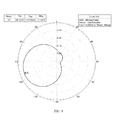
- the maximum gain of the RFID tag can reach to ⁇ 3.3924 dBi, which far more exceeds the existing miniaturized anti-metal tag.
- the antenna structure 20 is made of a copper material. However, this invention is not limited thereto. In other embodiments, the antenna structure 20 can be made of a metal material such as gold, silver, aluminum and so on, or a conductive alloy such as solder.
- the substrate 10 is an FR-4 epoxy glass fiber plate. However, this invention is not limited thereto. In other embodiments, the substrate 10 may be a plastic plate, a ceramic plate or a foam plate.
- the RFID tag is fixed in the main body of the insulated plug through the installation hole.
- an external reading and writing device can monitor an internal temperature of the insulated plug by reading the RFID tag.
- the tag antenna by forming the radiation part and the reflection part at both ends of the substrate and setting the reflection part to be closed, the energy radiated from the radiation part is superimposed after being reflected by the reflection part so as to increase the gain of the tag antenna and greatly increase the recognition distance of the tag antenna.
- the RFID tag antenna is attached to a metal (a fixing piece such as a nut), the reflection part can shield the effect of the metal located at the side of the reflection part so as to increase the recognition distance and achieve an anti-metal effect.
- the transmission coefficient of the antenna is increased, thereby increasing the recognition distance of the tag antenna.
- the gain of the antenna can be increased by increasing the thickness of the substrate such that the energy reflected by the reflection part and the energy radiated by the radiation part can be further superposed remotely to obtain a longer recognition distance.
Landscapes
- Engineering & Computer Science (AREA)
- Physics & Mathematics (AREA)
- Computer Hardware Design (AREA)
- Microelectronics & Electronic Packaging (AREA)
- General Physics & Mathematics (AREA)
- Theoretical Computer Science (AREA)
- Computer Networks & Wireless Communication (AREA)
- Electromagnetism (AREA)
- Details Of Aerials (AREA)
- Aerials With Secondary Devices (AREA)
Abstract
Description
Claims (8)
Applications Claiming Priority (3)
| Application Number | Priority Date | Filing Date | Title |
|---|---|---|---|
| CN201710153031 | 2017-03-15 | ||
| CN201710153031.4 | 2017-03-15 | ||
| CN201710153031.4A CN106876866B (en) | 2017-03-15 | 2017-03-15 | Insulating plug with RFID tag |
Publications (2)
| Publication Number | Publication Date |
|---|---|
| US20180268277A1 US20180268277A1 (en) | 2018-09-20 |
| US10417549B2 true US10417549B2 (en) | 2019-09-17 |
Family
ID=59171708
Family Applications (1)
| Application Number | Title | Priority Date | Filing Date |
|---|---|---|---|
| US15/922,859 Active US10417549B2 (en) | 2017-03-15 | 2018-03-15 | Insulated plug with RFID tag |
Country Status (2)
| Country | Link |
|---|---|
| US (1) | US10417549B2 (en) |
| CN (1) | CN106876866B (en) |
Families Citing this family (9)
| Publication number | Priority date | Publication date | Assignee | Title |
|---|---|---|---|---|
| CA3106395C (en) | 2018-11-09 | 2025-04-01 | Abb Schweiz Ag | Basic insulating plug and electric system |
| CN109509960B (en) * | 2019-01-22 | 2023-09-22 | 公安部交通管理科学研究所 | UHF RFID anti-metal tag antenna |
| CN110108372B (en) * | 2019-05-07 | 2024-06-18 | 杭州电力设备制造有限公司 | A wireless passive temperature sensor |
| CN110228502B (en) * | 2019-06-21 | 2021-03-02 | 中国神华能源股份有限公司 | Electronic tag for measuring axle temperature of railway vehicle and axle temperature measuring system |
| CN110659711A (en) * | 2019-10-16 | 2020-01-07 | 浙江悦和科技有限公司 | RFID temperature measurement label for cable joint, installation method and temperature measurement method |
| CN110718817A (en) * | 2019-11-11 | 2020-01-21 | 浙江悦和科技有限公司 | Plug-pull piece with temperature measurement function |
| CN110880635A (en) * | 2019-11-19 | 2020-03-13 | 浙江悦和科技有限公司 | RFID Tag Antenna, RFID Tag and Cable Connector |
| CN115117628B (en) * | 2022-06-10 | 2023-05-12 | 宁波大学 | Dual-frenquency point temperature measurement RFID tag antenna |
| EP4521296A1 (en) * | 2023-09-11 | 2025-03-12 | etifix GmbH | Smart label |
Citations (4)
| Publication number | Priority date | Publication date | Assignee | Title |
|---|---|---|---|---|
| US6441740B1 (en) * | 1998-02-27 | 2002-08-27 | Intermec Ip Corp. | Radio frequency identification transponder having a reflector |
| US20040183736A1 (en) * | 2003-01-31 | 2004-09-23 | Tdk Corporation | Antenna device and wireless communication apparatus using the same |
| US20140125460A1 (en) * | 2011-05-27 | 2014-05-08 | Michelin Recherche Et Technique S.A. | Rfid passive reflector for hidden tags |
| US9477921B2 (en) * | 2012-08-08 | 2016-10-25 | Harting Electric Gmbh & Co. Kg | Electrical connector housing having an RFID transponder |
Family Cites Families (12)
| Publication number | Priority date | Publication date | Assignee | Title |
|---|---|---|---|---|
| US7612676B2 (en) * | 2006-12-05 | 2009-11-03 | The Hong Kong University Of Science And Technology | RFID tag and antenna |
| KR100930157B1 (en) * | 2007-10-25 | 2009-12-07 | 테크노세미켐 주식회사 | Antenna for RFID tag and RFID tag |
| US8493279B2 (en) * | 2009-06-04 | 2013-07-23 | Ubiquiti Networks, Inc. | Antenna feed system |
| BR112012005903A2 (en) * | 2009-09-16 | 2018-03-20 | Prysmian S.P.A. | method and system for monitoring the twisting of a cable |
| CN103500353A (en) * | 2013-09-27 | 2014-01-08 | 爱康普科技(大连)有限公司 | An embedded anti-metal UHF RFID tag |
| CN203503789U (en) * | 2013-10-28 | 2014-03-26 | 唐山赛福特智能控制股份有限公司 | Subsize circular polarization ultrahigh frequency RFID reader fractal antenna |
| CN105990650A (en) * | 2015-02-15 | 2016-10-05 | 泰科电子(上海)有限公司 | Folded dipole antenna, wireless communication module and construction methods of folded dipole antenna and wireless communication module |
| CN105222915A (en) * | 2015-10-31 | 2016-01-06 | 深圳市金瑞铭科技有限公司 | A kind of cable temperature measuring equipment based on RFID technique |
| WO2017096420A1 (en) * | 2015-12-09 | 2017-06-15 | Licensys Australasia Pty Ltd | An antenna |
| CN105529520B (en) * | 2016-01-29 | 2018-04-20 | 华南师范大学 | Ultra wide band circular polarisation anti-metal is easy to the RFID label antenna of impedance adjusting |
| CN106229647A (en) * | 2016-07-20 | 2016-12-14 | 周丹 | An RFID electronic antenna tag |
| CN206585057U (en) * | 2017-03-15 | 2017-10-24 | 杭州泽济电子科技有限公司 | Insulation plug with RFID tag |
-
2017
- 2017-03-15 CN CN201710153031.4A patent/CN106876866B/en active Active
-
2018
- 2018-03-15 US US15/922,859 patent/US10417549B2/en active Active
Patent Citations (4)
| Publication number | Priority date | Publication date | Assignee | Title |
|---|---|---|---|---|
| US6441740B1 (en) * | 1998-02-27 | 2002-08-27 | Intermec Ip Corp. | Radio frequency identification transponder having a reflector |
| US20040183736A1 (en) * | 2003-01-31 | 2004-09-23 | Tdk Corporation | Antenna device and wireless communication apparatus using the same |
| US20140125460A1 (en) * | 2011-05-27 | 2014-05-08 | Michelin Recherche Et Technique S.A. | Rfid passive reflector for hidden tags |
| US9477921B2 (en) * | 2012-08-08 | 2016-10-25 | Harting Electric Gmbh & Co. Kg | Electrical connector housing having an RFID transponder |
Also Published As
| Publication number | Publication date |
|---|---|
| CN106876866A (en) | 2017-06-20 |
| US20180268277A1 (en) | 2018-09-20 |
| CN106876866B (en) | 2023-09-29 |
Similar Documents
| Publication | Publication Date | Title |
|---|---|---|
| US10417549B2 (en) | Insulated plug with RFID tag | |
| CN206585061U (en) | Anti-metal tag antenna and label | |
| US7750861B2 (en) | Hybrid antenna including spiral antenna and periodic array, and associated methods | |
| KR20070037694A (en) | Antenna, wireless device, antenna design method and measuring operating frequency of antenna | |
| Zachariades et al. | A wideband spiral UHF coupler with tuning nodules for partial discharge detection | |
| JP4896922B2 (en) | Radio tag and conductive pipe having radio tag | |
| Barman et al. | Spiral resonator loaded S‐shaped folded dipole dual band UHF RFID tag antenna | |
| CN104515940B (en) | A kind of uhf sensor for inside switch cabinet partial discharge monitoring | |
| CN102608506B (en) | Partial discharge ultrahigh-frequency detection Peano fractal antenna | |
| Nikitin et al. | Helical antenna for handheld UHF RFID reader | |
| Dong et al. | Design and testing of miniaturized dual-band microstrip antenna sensor for wireless monitoring of high temperatures | |
| Du et al. | Dual‐band metal skin UHF RFID tag antenna | |
| CN109917250B (en) | Multi-frequency broadband antenna for detecting partial discharge of electrical equipment and its design method | |
| CN104953260A (en) | Broadband planar helical antenna for detecting partial discharge of electrical equipment and design method thereof | |
| CN207440812U (en) | Anti-metal antenna, anti-metal tag and the insulation plug with anti-metal tag | |
| CN206585057U (en) | Insulation plug with RFID tag | |
| CN103777121A (en) | Multi-band ultrahigh frequency narrow band sensor for transformer substation local discharge detecting and positioning | |
| CN204966663U (en) | New -type 5DBI antenna structure | |
| Wang et al. | Design of a UHF antenna for partial discharge detection of power equipment | |
| CN201508905U (en) | Antenna applied to handheld reader and handheld reader | |
| Bandi et al. | A Multiple Narrow Band Antenna for Detection of Discharge‐Emitted Electromagnetic Waves for Insulation Diagnostic | |
| Khosronejad et al. | Design of an Archimedean spiral UHF antenna for pulse monitoring application | |
| Wang et al. | A multi frequency point broadband compound antenna for partial discharge detection in gas insulated switchgear | |
| CN103545601B (en) | A kind of on-line monitoring antenna | |
| Marchal et al. | Ultra-wide band antenna for partial discharge detection inside switchgear for on-line monitoring |
Legal Events
| Date | Code | Title | Description |
|---|---|---|---|
| AS | Assignment |
Owner name: HANGZHOU ZEJI ELECTRONICS TECHNOLOGY CO., LTD., CH Free format text: ASSIGNMENT OF ASSIGNORS INTEREST;ASSIGNOR:JI, HONGHONG;REEL/FRAME:045244/0042 Effective date: 20180306 |
|
| FEPP | Fee payment procedure |
Free format text: ENTITY STATUS SET TO UNDISCOUNTED (ORIGINAL EVENT CODE: BIG.); ENTITY STATUS OF PATENT OWNER: MICROENTITY |
|
| FEPP | Fee payment procedure |
Free format text: ENTITY STATUS SET TO SMALL (ORIGINAL EVENT CODE: SMAL); ENTITY STATUS OF PATENT OWNER: MICROENTITY Free format text: ENTITY STATUS SET TO MICRO (ORIGINAL EVENT CODE: MICR); ENTITY STATUS OF PATENT OWNER: MICROENTITY |
|
| STPP | Information on status: patent application and granting procedure in general |
Free format text: DOCKETED NEW CASE - READY FOR EXAMINATION |
|
| STPP | Information on status: patent application and granting procedure in general |
Free format text: EX PARTE QUAYLE ACTION MAILED |
|
| STPP | Information on status: patent application and granting procedure in general |
Free format text: RESPONSE TO EX PARTE QUAYLE ACTION ENTERED AND FORWARDED TO EXAMINER |
|
| STPP | Information on status: patent application and granting procedure in general |
Free format text: NOTICE OF ALLOWANCE MAILED -- APPLICATION RECEIVED IN OFFICE OF PUBLICATIONS |
|
| AS | Assignment |
Owner name: ZHEJIANG JOHAR TECHNOLOGY CO., LTD., CHINA Free format text: ASSIGNMENT OF ASSIGNORS INTEREST;ASSIGNOR:HANGZHOU ZEJI ELECTRONICS TECHNOLOGY CO., LTD.;REEL/FRAME:049795/0686 Effective date: 20190705 |
|
| STPP | Information on status: patent application and granting procedure in general |
Free format text: PUBLICATIONS -- ISSUE FEE PAYMENT VERIFIED |
|
| STCF | Information on status: patent grant |
Free format text: PATENTED CASE |
|
| MAFP | Maintenance fee payment |
Free format text: PAYMENT OF MAINTENANCE FEE, 4TH YEAR, MICRO ENTITY (ORIGINAL EVENT CODE: M3551); ENTITY STATUS OF PATENT OWNER: MICROENTITY Year of fee payment: 4 |