US1041663A - Gate. - Google Patents
Gate. Download PDFInfo
- Publication number
- US1041663A US1041663A US69444412A US1912694444A US1041663A US 1041663 A US1041663 A US 1041663A US 69444412 A US69444412 A US 69444412A US 1912694444 A US1912694444 A US 1912694444A US 1041663 A US1041663 A US 1041663A
- Authority
- US
- United States
- Prior art keywords
- draw
- gates
- shaft
- bridge
- gate
- Prior art date
- Legal status (The legal status is an assumption and is not a legal conclusion. Google has not performed a legal analysis and makes no representation as to the accuracy of the status listed.)
- Expired - Lifetime
Links
- 238000010276 construction Methods 0.000 description 3
- 239000011435 rock Substances 0.000 description 3
- 241000588278 Osmanthus heterophyllus Species 0.000 description 2
Images

Classifications
-
- E—FIXED CONSTRUCTIONS
- E01—CONSTRUCTION OF ROADS, RAILWAYS, OR BRIDGES
- E01D—CONSTRUCTION OF BRIDGES, ELEVATED ROADWAYS OR VIADUCTS; ASSEMBLY OF BRIDGES
- E01D15/00—Movable or portable bridges; Floating bridges
- E01D15/005—Movable bridges in general ; Constructional elements peculiar to movable bridges
Definitions
- This invention relates to improvements in gates employed in connection with draw bridges, and the principal object of the invention is to provide a gate which is normally held open by a novel mechanism when the draw is closed, and which is automatically lowered when the draw is opened.
- Another object of the invention is to provide gates which are respectively arranged 011 either side of the draw and which are adapted to be actuated by said draw irrespective of the direction of movement thereof.
- a further object of the invention is .to.
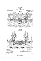
- Figure 1 is a top plan view of a draw bridge showing the application of my invention
- Fig. 2 is a transverse sectional view taken on the line 22 of Fig. 1, the gates being shown in a closed position
- Fig. 3 is a similar view but showing the gates in their elevated positions
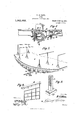
- Fig. 4 is a detail longitudinal sectional view showing the connection between the draw and the rock shaft
- Fig. 5 is a detail perspective view of one end of the draw showing the connection between the gate and the rocker arm
- Fig. 6 is a perspective view of one of the gates
- Fig. 7 is a perspective view of the Specification of Letters Patent.
- Fig. 8 is a perspective view of a cross head and rack bar.
- 5 designates a bridge of any suitable construction which includesthe usual draw or turntable 6. Any suitable mechanism (not shown) may be employed to rotate said draw.
- the bridge includes the usual sidewalks A-A on either side thereof and the roadway B which is centrally disposed between said sidewalks.
- each casing 7 Disposed on either side of the approach 5 is a pair of transversely alined casings 77, said casings being disposed on either side of the roadway B.
- segmental gears 88 Disposed on either side of the approach 5 are opposed segmental gears 88, each gear terminating at its outer end in an arm 9..
- Gates 101O of any suitable construction are secured at one end to the respective arms 9 and are adapted to swing in a ninety degree are by a mechanism hereinafter more fully described, one of said gates projecting partially over the roadway B and the other projecting over a respective sidewalk A.
- gears 8 are disposed in alinement and in spaced relation and arranged therebetween and engaging said gears is a double-faced rack bar 11 which extends downwardly and is connected at its lower end to a cross head 11%, said cross head being mounted to slide vertically between suitable guide strips 12.
- a pitman 13 has its upper end pivotally connected to the cross head and this pitman extends downwardly through a suitable opening formed in the bridge 5.
- Supported by the bridge and in alinement with the respective pairs of casings 77 are alined crank shafts 14.14@, each shaft having a crank 15 which is operatively connected to the lower end of a respective pitman 13.
- each shaft 19 is supported in suitable brackets 16, and mounted upon the inner end of each shaftis a bevel gear 17 and these gears are simultaneously driven by a main bevel gear 18 which is mounted on a longitudinally disposed rock shaft 19 that is suitably supported from the bridge by means of brackets 20.
- the inner end of each shaft 19 extends below the outer edge of the draw or turntable 6, and associated with each end is a rocker arm 21 which carries at its free end a roller 22 which is adapted to be engaged by one of a pair of diametrically opposed cam plates 23 which are carried by the draw.
- rocker arms 21 are disposed in horizontal planes, and are held in such positions by means of the cams 23, it being understood of course that the draw 6 is in its closed position.
- the cams 23 will of course become disengaged from the rocker arms 21 and in order to assist in the rotation of the shaft 19 so as to lower the gates 10, the shaft 19 is provided with an arm 24; which is disposed in alinement with the rocker arm 21, and this arm carries a weight 25.
- the weights 25 will assist in rotating the shaft 19 and this shaft, through the beveled gear 19 and gears 17 will rotate the crank shafts 14.
- crank shafts will in turn,- through the medium of the cranks 15 raise the cross heads 11 through the medium of the pitmen 13 and consequently elevate the rack bars 11 which in turn will actuate the segments 8 to swing the gates downwardly so as to close the bridge.
- the cams 23 will of course engage the rollers 22 of the rocker arms 21 and will rotate the shaft 19 against the weight 25. This movement will return the parts to their normal positions, and as a result the gates 10 will be disposed in an elevated position, thereby opening the bridge to traffic.
Landscapes
- Engineering & Computer Science (AREA)
- Architecture (AREA)
- Civil Engineering (AREA)
- Structural Engineering (AREA)
- Low-Molecular Organic Synthesis Reactions Using Catalysts (AREA)
Description
W. H. OLIVE.
GATE.
APPLIGATION FILED MAY 1, 1912.
Patented Oct. 15, 1912.
3 SHEETS-SHEET 1.
W. H. OLIVE.
GATE.
APPLICATION FILED MAY 1, 1912.
cnLuMglA PLANDGRAPH 60., WASHINGTON. D. c.
Patented Oct. 15, 1912.
3 SHEETS-SHEET 2.
W. H. OLIVE.
GATE.
APPLICATION FILED MAY 1, 1912.
1,041,663. Patented Oct. 15, 1912.
I 3 SHEETS-SHEET 3.
@XMMMM I l I 1 w a "z a 1 l-DLUMBA Non TED STATES WILLIAM H. OLIVE, OFMENOIVIINEE, MICHIGAN.
GATE.
Application filed May 1, 1912. Serial No. 694,444.
To all whom it may concern:
Be it known that I, WILLIAM H. OLIVE, a citizen of the United States, residing at Menominee, in the county of Menominee, State of Michigan, have invented certain new and useful Improvements in Gates; and
I do hereby declare the following to be a full, clear, and exact description of the in vention, such as will enable others skilled in the art to which it appertains to make and use the same.
This invention relates to improvements in gates employed in connection with draw bridges, and the principal object of the invention is to provide a gate which is normally held open by a novel mechanism when the draw is closed, and which is automatically lowered when the draw is opened.
Another object of the invention is to provide gates which are respectively arranged 011 either side of the draw and which are adapted to be actuated by said draw irrespective of the direction of movement thereof.
A further object of the invention is .to.
novel combination of parts hereinafter fully described, illustrated in the accompanying drawings and pointed out in the claims hereto appended; it being understood that various changes in the form, proportion, size and minor details of construction within the scope of the claims may be resorted to without departing from the spirit or sacrificing any of the advantages of the invention.
In the drawings: Figure 1 is a top plan view of a draw bridge showing the application of my invention, Fig. 2 is a transverse sectional view taken on the line 22 of Fig. 1, the gates being shown in a closed position, Fig. 3 is a similar view but showing the gates in their elevated positions, Fig. 4 is a detail longitudinal sectional view showing the connection between the draw and the rock shaft, Fig. 5 is a detail perspective view of one end of the draw showing the connection between the gate and the rocker arm, Fig. 6 is a perspective view of one of the gates, Fig. 7 is a perspective view of the Specification of Letters Patent.
Patented Oct. 15,1912.
rocker arm, and Fig. 8 is a perspective view of a cross head and rack bar.
Like reference numerals designate corresponding parts in allt-he figures of the drawlngs.
Referring to the drawings, 5 designates a bridge of any suitable construction which includesthe usual draw or turntable 6. Any suitable mechanism (not shown) may be employed to rotate said draw. The bridge includes the usual sidewalks A-A on either side thereof and the roadway B which is centrally disposed between said sidewalks.
Disposed on either side of the approach 5 is a pair of transversely alined casings 77, said casings being disposed on either side of the roadway B. -Pivotally mounted on opposite sides of the upper end of each casing 7 are opposed segmental gears 88, each gear terminating at its outer end in an arm 9.. Gates 101O of any suitable construction are secured at one end to the respective arms 9 and are adapted to swing in a ninety degree are by a mechanism hereinafter more fully described, one of said gates projecting partially over the roadway B and the other projecting over a respective sidewalk A. These gears 8 are disposed in alinement and in spaced relation and arranged therebetween and engaging said gears is a double-faced rack bar 11 which extends downwardly and is connected at its lower end to a cross head 11%, said cross head being mounted to slide vertically between suitable guide strips 12. A pitman 13 has its upper end pivotally connected to the cross head and this pitman extends downwardly through a suitable opening formed in the bridge 5. Supported by the bridge and in alinement with the respective pairs of casings 77 are alined crank shafts 14.14@, each shaft having a crank 15 which is operatively connected to the lower end of a respective pitman 13. These shafts are supported in suitable brackets 16, and mounted upon the inner end of each shaftis a bevel gear 17 and these gears are simultaneously driven by a main bevel gear 18 which is mounted on a longitudinally disposed rock shaft 19 that is suitably supported from the bridge by means of brackets 20. The inner end of each shaft 19 extends below the outer edge of the draw or turntable 6, and associated with each end is a rocker arm 21 which carries at its free end a roller 22 which is adapted to be engaged by one of a pair of diametrically opposed cam plates 23 which are carried by the draw.
Normally the rocker arms 21 are disposed in horizontal planes, and are held in such positions by means of the cams 23, it being understood of course that the draw 6 is in its closed position. As soon as the draw 6 is swung around, the cams 23 will of course become disengaged from the rocker arms 21 and in order to assist in the rotation of the shaft 19 so as to lower the gates 10, the shaft 19 is provided with an arm 24; which is disposed in alinement with the rocker arm 21, and this arm carries a weight 25. As a result, as soon as the cams 23 become disengaged from the respective rocker arms, the weights 25 will assist in rotating the shaft 19 and this shaft, through the beveled gear 19 and gears 17 will rotate the crank shafts 14. These crank shafts will in turn,- through the medium of the cranks 15 raise the cross heads 11 through the medium of the pitmen 13 and consequently elevate the rack bars 11 which in turn will actuate the segments 8 to swing the gates downwardly so as to close the bridge. When the draw is returned to its normal position, the cams 23 will of course engage the rollers 22 of the rocker arms 21 and will rotate the shaft 19 against the weight 25. This movement will return the parts to their normal positions, and as a result the gates 10 will be disposed in an elevated position, thereby opening the bridge to traffic.
What is claimed is:
In combination with a bridge and its turntable, of a casing supported by the bridge opposed segmental gears pivotally mounted in the casing, gates respectively carried by said gears, a double-faced rack bar disposed between and engaging said gears, a rock shaft longitudinally supported below the bridge and havingone end projecting under the turntable, operative connections between said shaft and the rack bar, a rocker arm fixedly connected on the projecting end of said shaft, means carried by .the turntable for engagement with the rocker arm to rotate said shaft, an arm projecting from the shaft and arranged in alinement with the rocker arm, and a weight carried by said arm for returning the gates to their upright positions. 1
In testimony whereof, I afiix my signature, in presence of two witnesses.
WILLIAM H. OLIVE. Witnesses:
JOHN MCDONALD, MICHAEL SULLIVAN.
Copies of this patent may be obtained for five cents each, by addressing the Commissioner of Patents,
Washington, D. G.
Priority Applications (1)
| Application Number | Priority Date | Filing Date | Title |
|---|---|---|---|
| US69444412A US1041663A (en) | 1912-05-01 | 1912-05-01 | Gate. |
Applications Claiming Priority (1)
| Application Number | Priority Date | Filing Date | Title |
|---|---|---|---|
| US69444412A US1041663A (en) | 1912-05-01 | 1912-05-01 | Gate. |
Publications (1)
| Publication Number | Publication Date |
|---|---|
| US1041663A true US1041663A (en) | 1912-10-15 |
Family
ID=3109938
Family Applications (1)
| Application Number | Title | Priority Date | Filing Date |
|---|---|---|---|
| US69444412A Expired - Lifetime US1041663A (en) | 1912-05-01 | 1912-05-01 | Gate. |
Country Status (1)
| Country | Link |
|---|---|
| US (1) | US1041663A (en) |
-
1912
- 1912-05-01 US US69444412A patent/US1041663A/en not_active Expired - Lifetime
Similar Documents
| Publication | Publication Date | Title |
|---|---|---|
| US1041663A (en) | Gate. | |
| US955540A (en) | Automatic door and mechanism for operating the same. | |
| US117418A (en) | Improvement in gates | |
| US613568A (en) | Safety-gate for bridges | |
| US1027100A (en) | Signal device for drawbridges, &c. | |
| US345150A (en) | Bridge-gate | |
| US620116A (en) | fusch | |
| US431817A (en) | Bridge-gate | |
| US152415A (en) | Improvement in gates for railway-crossings | |
| US1041359A (en) | Safety drawbridge attachment. | |
| US114414A (en) | Improvement in bridge-gates | |
| US396662A (en) | Draw-bridge gate | |
| US4307A (en) | Andrew hood | |
| US1242190A (en) | Means for automatically opening mine-doors. | |
| US192882A (en) | Improvement in gates for railroads | |
| US433949A (en) | Bridge-gate | |
| US226223A (en) | Dredging-machine | |
| US486738A (en) | Safety-gate for bridges | |
| US1294152A (en) | Railroad-crossing gate. | |
| US1031547A (en) | Automatic gate for railroads. | |
| US449022A (en) | Sliding gate for draw-bridges | |
| US820409A (en) | Stock-chute. | |
| US309697A (en) | Bridge-gate | |
| US342270A (en) | Josep staeka | |
| USRE7897E (en) | Improvement in gates |