US10405802B2 - Method for detecting a heart rate - Google Patents
Method for detecting a heart rate Download PDFInfo
- Publication number
- US10405802B2 US10405802B2 US14/918,551 US201514918551A US10405802B2 US 10405802 B2 US10405802 B2 US 10405802B2 US 201514918551 A US201514918551 A US 201514918551A US 10405802 B2 US10405802 B2 US 10405802B2
- Authority
- US
- United States
- Prior art keywords
- heart rate
- interval
- frequency
- peaks
- indexes
- Prior art date
- Legal status (The legal status is an assumption and is not a legal conclusion. Google has not performed a legal analysis and makes no representation as to the accuracy of the status listed.)
- Active, expires
Links
- 238000000034 method Methods 0.000 title claims abstract description 68
- 230000033001 locomotion Effects 0.000 claims abstract description 60
- 238000005070 sampling Methods 0.000 claims abstract description 15
- 238000001228 spectrum Methods 0.000 claims description 29
- 238000013186 photoplethysmography Methods 0.000 claims description 21
- 210000004204 blood vessel Anatomy 0.000 claims description 4
- 238000010586 diagram Methods 0.000 description 10
- 230000003595 spectral effect Effects 0.000 description 5
- 239000003086 colorant Substances 0.000 description 4
- 230000000694 effects Effects 0.000 description 4
- 230000017531 blood circulation Effects 0.000 description 3
- 238000002565 electrocardiography Methods 0.000 description 3
- 238000005452 bending Methods 0.000 description 2
- 230000008901 benefit Effects 0.000 description 2
- 238000004364 calculation method Methods 0.000 description 2
- 238000007796 conventional method Methods 0.000 description 2
- 238000012986 modification Methods 0.000 description 2
- 230000004048 modification Effects 0.000 description 2
- 230000003068 static effect Effects 0.000 description 2
- 230000001133 acceleration Effects 0.000 description 1
- 238000013461 design Methods 0.000 description 1
- 238000001514 detection method Methods 0.000 description 1
- 238000011161 development Methods 0.000 description 1
- 230000018109 developmental process Effects 0.000 description 1
- 229940079593 drug Drugs 0.000 description 1
- 239000003814 drug Substances 0.000 description 1
- 210000004247 hand Anatomy 0.000 description 1
- 238000005259 measurement Methods 0.000 description 1
- 238000012544 monitoring process Methods 0.000 description 1
- 230000000630 rising effect Effects 0.000 description 1
- 230000036555 skin type Effects 0.000 description 1
- 210000004243 sweat Anatomy 0.000 description 1
- 210000000707 wrist Anatomy 0.000 description 1
Images


Classifications
-
- A—HUMAN NECESSITIES
- A61—MEDICAL OR VETERINARY SCIENCE; HYGIENE
- A61B—DIAGNOSIS; SURGERY; IDENTIFICATION
- A61B5/00—Measuring for diagnostic purposes; Identification of persons
- A61B5/72—Signal processing specially adapted for physiological signals or for diagnostic purposes
- A61B5/7235—Details of waveform analysis
- A61B5/7253—Details of waveform analysis characterised by using transforms
- A61B5/7257—Details of waveform analysis characterised by using transforms using Fourier transforms
-
- A—HUMAN NECESSITIES
- A61—MEDICAL OR VETERINARY SCIENCE; HYGIENE
- A61B—DIAGNOSIS; SURGERY; IDENTIFICATION
- A61B5/00—Measuring for diagnostic purposes; Identification of persons
- A61B5/02—Detecting, measuring or recording pulse, heart rate, blood pressure or blood flow; Combined pulse/heart-rate/blood pressure determination; Evaluating a cardiovascular condition not otherwise provided for, e.g. using combinations of techniques provided for in this group with electrocardiography or electroauscultation; Heart catheters for measuring blood pressure
- A61B5/024—Detecting, measuring or recording pulse rate or heart rate
- A61B5/02416—Detecting, measuring or recording pulse rate or heart rate using photoplethysmograph signals, e.g. generated by infrared radiation
-
- A—HUMAN NECESSITIES
- A61—MEDICAL OR VETERINARY SCIENCE; HYGIENE
- A61B—DIAGNOSIS; SURGERY; IDENTIFICATION
- A61B5/00—Measuring for diagnostic purposes; Identification of persons
- A61B5/02—Detecting, measuring or recording pulse, heart rate, blood pressure or blood flow; Combined pulse/heart-rate/blood pressure determination; Evaluating a cardiovascular condition not otherwise provided for, e.g. using combinations of techniques provided for in this group with electrocardiography or electroauscultation; Heart catheters for measuring blood pressure
- A61B5/024—Detecting, measuring or recording pulse rate or heart rate
- A61B5/02438—Detecting, measuring or recording pulse rate or heart rate with portable devices, e.g. worn by the patient
-
- A—HUMAN NECESSITIES
- A61—MEDICAL OR VETERINARY SCIENCE; HYGIENE
- A61B—DIAGNOSIS; SURGERY; IDENTIFICATION
- A61B5/00—Measuring for diagnostic purposes; Identification of persons
- A61B5/145—Measuring characteristics of blood in vivo, e.g. gas concentration, pH value; Measuring characteristics of body fluids or tissues, e.g. interstitial fluid, cerebral tissue
- A61B5/1455—Measuring characteristics of blood in vivo, e.g. gas concentration, pH value; Measuring characteristics of body fluids or tissues, e.g. interstitial fluid, cerebral tissue using optical sensors, e.g. spectral photometrical oximeters
- A61B5/14551—Measuring characteristics of blood in vivo, e.g. gas concentration, pH value; Measuring characteristics of body fluids or tissues, e.g. interstitial fluid, cerebral tissue using optical sensors, e.g. spectral photometrical oximeters for measuring blood gases
- A61B5/14552—Details of sensors specially adapted therefor
-
- A—HUMAN NECESSITIES
- A61—MEDICAL OR VETERINARY SCIENCE; HYGIENE
- A61B—DIAGNOSIS; SURGERY; IDENTIFICATION
- A61B5/00—Measuring for diagnostic purposes; Identification of persons
- A61B5/72—Signal processing specially adapted for physiological signals or for diagnostic purposes
- A61B5/7203—Signal processing specially adapted for physiological signals or for diagnostic purposes for noise prevention, reduction or removal
- A61B5/7207—Signal processing specially adapted for physiological signals or for diagnostic purposes for noise prevention, reduction or removal of noise induced by motion artifacts
- A61B5/721—Signal processing specially adapted for physiological signals or for diagnostic purposes for noise prevention, reduction or removal of noise induced by motion artifacts using a separate sensor to detect motion or using motion information derived from signals other than the physiological signal to be measured
-
- A—HUMAN NECESSITIES
- A61—MEDICAL OR VETERINARY SCIENCE; HYGIENE
- A61B—DIAGNOSIS; SURGERY; IDENTIFICATION
- A61B2562/00—Details of sensors; Constructional details of sensor housings or probes; Accessories for sensors
- A61B2562/02—Details of sensors specially adapted for in-vivo measurements
- A61B2562/0219—Inertial sensors, e.g. accelerometers, gyroscopes, tilt switches
-
- A—HUMAN NECESSITIES
- A61—MEDICAL OR VETERINARY SCIENCE; HYGIENE
- A61B—DIAGNOSIS; SURGERY; IDENTIFICATION
- A61B5/00—Measuring for diagnostic purposes; Identification of persons
- A61B5/103—Detecting, measuring or recording devices for testing the shape, pattern, colour, size or movement of the body or parts thereof, for diagnostic purposes
- A61B5/11—Measuring movement of the entire body or parts thereof, e.g. head or hand tremor, mobility of a limb
Definitions
- the present invention relates to a method for detecting a heart rate, and more particularly to a method for detecting a heart rate during exercise.
- biosensors for detecting the physiological signals are applied in large medical equipment.
- wearable devices which were originally applied for medical purposes can also be the ones for the purposes of health and fitness. Because the market for wearable devices is growing, the application of biosensors to wearable devices has attracted more and more attention.
- the method for detecting a heart rate in a wearable device is to measure the signal for the change of the vessel volume, and this signal is measured by recording and sensing the energy variation of light using photoplethysmography (PPG). Because the heart beats are periodically verified, the volume of the blood flow in the vessels per unit of cross-sectional area will change periodically. When the volume of the blood flow per unit of cross-sectional area changes, voltage signals, current signals or resistance signals will be detected by a photodetector with the variation of the volume of the blood flow.
- PPG photoplethysmography
- the signals detected by the photodector may be interfered with and there is substantial noise in the signal because of the human body's motions during exercise, which causes serious distortion of the detected heart rate.
- static activities such as pressing the keys of a keyboard or writing also cause the distortion of the detected heart rate.
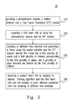
- a method for detecting a heart rate includes providing a photodetector module, a motion detector and a Fast Fourier Transform (FFT) module; acquiring a first heart rate by using the photodetector module and the FFT module; sampling at different time intervals and generating a frame using the motion detector and the FFT module, wherein the frame has a first plurality of peaks and a first plurality of indexes corresponding to the first plurality of peaks, and a plurality of sport intervals are defined by the first plurality of indexes; and acquiring a present heart rate by applying an interval tracking algorithm with the first heart rate and the plurality of sport intervals generated from the sampling at different time intervals.
- FFT Fast Fourier Transform
- a method for detecting a heart rate includes acquiring a motion signal of a sporter; acquiring a first heart rate from a first heart rate spectrum of the sporter at a first time interval and a second heart rate spectrum of the sporter at a second time interval, wherein the second heart rate spectrum has a first plurality of peaks and a first plurality of indexes corresponding to the first plurality of peaks; acquiring a frame of the motion signal at the second time interval, wherein the frame has a second plurality of peaks; defining the second plurality of peaks with a second plurality of indexes, and marking a first position corresponding to the first heart rate; and selecting a peak from the first plurality of peaks corresponding to a plurality of positions of the second plurality of indexes as a second heart rate, wherein the peak has a specific mathematical relationship with the first position.
- a method for detecting a heart rate includes acquiring a first heart rate from a first heart rate spectrum of a sporter at a first time interval and a second heart rate spectrum of the sporter at a second time interval, wherein the second heart rate spectrum has a first plurality of peaks and a first plurality of indexes corresponding to the first plurality of peaks; marking the first heart rate in a first position of a first plurality of frequency intervals; and selecting a specific peak from the first plurality of peaks, which has a specific mathematical relationship with the first position, and is a second heart rate.
- FIG. 1 is a diagram showing a system for detecting a heart rate according to a first embodiment in the present invention
- FIG. 2 is a flow chart of detecting a heart rate according to the first embodiment in the present invention
- FIG. 3 is a schematic diagram of acquiring signals of a photodetector using a photodetector module according to the first embodiment in the present invention
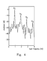
- FIG. 4 is a spectral distribution of the signals of the photodetector according to the first embodiment in the present invention.
- FIG. 5 is a spectral distribution of motion signals according to the first embodiment in the present invention.
- FIG. 6 is a schematic diagram of determining an activity mode of a human body according to the first embodiment in the present invention.
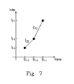
- FIG. 7 is a diagram showing the time versus heart rate according to the first embodiment in the present invention.
- FIGS. 8( a ) and 8( b ) are schematic diagrams showing the sport intervals according to the first embodiment in the present invention.
- FIG. 9 is the result of the heart rate detected by the conventional electrocardiography (ECG) method.
- FIG. 10 is the result of the heart rate detected by the method for detecting a heart rate according to the first embodiment in the present invention.
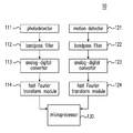
- FIG. 1 is a diagram showing a system 10 for detecting a heart rate according to a first embodiment in the present invention.
- the system 10 includes a photodetector 111 , a motion detector 121 , bandpass filters (BPF) 112 and 122 , analog-digital converters (ADC) 113 and 123 , fast Fourier transform (FFT) modules 114 and 124 , and a micro processor 130 .
- BPF bandpass filters
- ADC analog-digital converters
- FFT fast Fourier transform
- FIG. 2 is a flow chart of detecting a heart rate according to the first embodiment in the present invention.
- step 210 of the method 20 a photodetector 111 , a motion detector 121 and FFT modules 114 and 124 are provided.
- FIG. 3 is a schematic diagram of acquiring signals of a photodetector using a photodetector module 300 according to the first embodiment. After the light beams of the light sources 310 and 320 are illuminated to the vessel 340 in the corium layer, the photodetector 330 receives the reflected light and converts a light signal from the reflected light to an analog signal.
- the photodetector 330 is the TSL-12T Light-to-Voltage Convertor produced by the AMS Corporation (Austria).
- the photodetector 330 converts the harvested reflected light signals to voltage signals, so as to obtain a PPG diagram.
- the reflectance and the signal-to-noise ratio (SNR) of light depend on the wavelength of the light and the skin color illuminated by the light, and the SNRs with regard to different skin colors are verified during exercise.
- index 0 0 Hz
- index 1 0.0625 Hz
- index 2 0.125 Hz
- index 3 0.1875 Hz
- . . . and index 127 7.9375 Hz.
- the frequency unit at the x-axis also corresponds to the index unit according to the above-mentioned relationship between the index and the frequency.
- the spectral distribution of the PPG is acquired.
- the acquired data are transmitted to the microprocessor 130 to obtain a frame having a plurality of indexes corresponding to a plurality of peaks, and then the plurality of indexes are arranged according to their amplitudes.
- the signals/data converted by the ADC 113 are successively generated over time, and old data will be overwritten by the newly-generated data. When all or part of the old data are updated, the FFT are performed to obtain a new frame and a new HR′ set.
- his/her PPG signal is a harmonic signal which includes a fundamental frequency and a plurality of harmonic frequencies.
- a frame is generated using the motion detector and the FFT module at the different time intervals, wherein the frame has a plurality of peaks and a first plurality of indexes corresponding to the plurality of peaks, and a plurality of sport intervals are defined by the first plurality of indexes.
- the motion signals are obtained using a motion detector 121 .
- a tri-axis accelerometer (hereinafter abbreviated as “G-sensor”) is used as the motion detector in this embodiment, and preferably is the KXTJ2-1009 tri-axis accelerometer produced by Kionix Corporation (Ithaca, N.Y., U.S.A.).
- the motion signals are transmitted to a micro-control unit (MCU) via the fast-mode I 2 C and filtered using the BPF 122 .
- the sampling frequency of the motion detector 121 is the integral multiple to that of the ADC 123 , but the sampling period of the motion detector 121 is the same as that of the ADC 123 .
- the obtained data are transmitted to the microprocessor 130 , and the result is shown in FIG. 5 .
- a GR′ set is defined as the set of the sport indexes.
- the motion signal at the condition of the regular motion is a harmonic signal which includes a fundamental frequency and a plurality of harmonic frequencies, and thus there are multiple between the sport indexes.
- the set S 1 ′ is the index set having indexes from index min to gr 1
- the set S 2 ′ is the index set having indexes from gr 1 +1 to gr 2
- the set S 3 ′ is the index set having indexes from gr 2 +1 to gr 3
- the set S 4 ′ is the index set having indexes from gr 3 +1 to index max
- S ⁇ S1′ S2′ S3′ S4′ ⁇ .
- FIG. 6 is a schematic diagram of determining an activity mode of a human body according to the first embodiment in the present invention.
- the activity mode of the human body is divided into an initial mode, a rest mode and a sport mode using the G-sensor.
- the mode is switched among these three modes according to the signals received by the G-sensor:
- the initial mode The measurement of the heart rate can be performed only when the user is in the rest condition.
- the ADC data of 2 N points are obtained after T seconds, and the HR′ set is calculated by the FFT, wherein hr 1 is the index of the present heart rate (hr L ).
- the sport mode When GR′ ⁇ , it means that the user is doing regular sports.
- the index of the heart rate before three frames (D t-3 ) is recorded as I t-3
- the index of the heart rate before two frames (D t-2 ) is recorded as I t-2
- the index of the heart rate before one frame (D t-1 ) is recorded as I t-1
- the index I t-1 is also the index of the previous heart rate (hr P ).
- Equation (2) is used to calculate the slope E 23 from D t-3 to D t-2 and the slope E 12 from D t-2 to D t-1 .
- E 23 I t - 2 - I t - 3 D t - 2 - D t - 3
- E 12 I t - 1 - I t - 2 D t - 1 - D t - 2 ⁇ ( 2 )
- the initial mode Because the user is in the rest condition, the signals received by the photodetector will not be interfered with by other frequencies.
- the index hr 1 generated from the signal of 2 N points after the FFT is the index of the present heart rate (hr L ), the index of the previous heart rate (hr P ) is recorded as a new index hr 1 , and then the initial mode switches to the rest mode.
- a present heart rate for a specific time is determined within each frame.
- the two parameters hr L and hr P used in this embodiment are defined based on the result observed at a specific time, and will change according to the various observation times. For instance, if the specific observation time is at frame #3, the present heart rate for frame #3 is hr L , and the heart rate for frame #2 (i.e. the previous heart rate for frame #3) is hr P . If the specific observation time is at frame #2, the present heart rate for frame #2 is hr L , and the heart rate for frame #1 (the previous heart rate for frame #2) is hr P .
- the rest mode There is also no interference from other frequencies because of the rest mode, and thus the new index hr 1 generated from the new frame is hr L .
- bending the fingers may cause the skin of the fingers to undulate, and the detected PPG signal has no characteristics of the harmonic frequency at this moment (i.e. it does not conform with equation (1)).
- This situation is called the slight motion mode, and the obtained index hr 1 at this moment may be the index of the frequency of the bending fingers rather than the index of the heart rate.
- hr L ⁇ hr 1 , ⁇ hr p - hr 1 ⁇ ⁇ ⁇ ⁇ ⁇ s hr 2 , ⁇ hr p - hr 2 ⁇ ⁇ ⁇ ⁇ ⁇ s hr 3 , ⁇ hr p - hr 3 ⁇ ⁇ ⁇ ⁇ ⁇ s hr 4 , ⁇ hr p - hr 4 ⁇ ⁇ ⁇ ⁇ ⁇ s hr p , otherwise ( 3 )
- a present heart rate is obtained by an interval tracking algorithm using the first heart rate and the plurality of sport intervals generated from the different sampling time intervals, and the description is illustrated in the next paragraph.
- the photodector may produce a lot of statistical noise because of the movement of the human body during exercise, and thus the present heart rate cannot be obtained directly from the PPG spectrum.
- S′ P ⁇ S is defined as a sport interval where the index hr L for the previous frame is situated, and S′ P is the P th interval for the previous frame
- S′ L ⁇ S is defined as a sport interval where the index hr P for the present frame is situated, and S′ L is the L th interval of the present frame.
- FIGS. 8( a ) and 8( b ) are schematic diagrams showing the sport intervals according to the first embodiment in the present invention, wherein the spectrum of the motion signals shown in FIG.
- FIG. 8( a ) shows the sport intervals defined by the previous frame
- FIG. 8( b ) shows the sport intervals defined by the present frame.
- the index hr L for the previous frame is index 21 (i.e., 1.3125 Hz, or 79 heart beats per minute)
- the present heart rate is obtained according to the relationship between the sport mode of the human body and his/her heart rate in the present invention.
- the relationship between the present heart rate and the sport intervals can be grouped as the following cases:
- hr i (which is the closest to hr P among the index set HR′′) from HR′′, wherein the index hr i must satisfy the condition of ⁇
- hr i (which is the closest to hr P among the index set HR′′) from HR′′, wherein the index hr i must satisfy the condition of ⁇
- hr i (which is the closest to hr P among HR′′) from HR′′, wherein the hr i must satisfy the condition of ⁇
- hr L ⁇ hr P - 3 , 4 ⁇ E 12 E 23 ⁇ 3 hr P - 2 , 3 ⁇ E 12 E 23 ⁇ 2 hr P - 1 , 2 ⁇ E 12 E 23 ⁇ 0 hr P , otherwise ( 6 )
- FIGS. 9 and 10 show the heart rates of one user detected by different methods.
- FIG. 9 shows the heart rate detected by the conventional ECG method.
- the ECG is one of the most accurate methods for detecting the heart rate in the conventional techniques.
- FIG. 10 shows the heart rate detected by the method for detecting a heart rate in the present invention. According to the experimental results described in the previous paragraph [0036] and comparing FIG. 9 with FIG. 10 , it can be seen that the heart rate detected by the method in the present invention still is very accurate without distortion even during sports.
- the present invention discloses a method for detecting the heart rate.
- a plurality of sport intervals are defined by the fundamental frequency and the harmonic frequencies of the motion signal during exercise, and the sport interval where the heart rate is located can be figured out according to the relationship between the human sport activity mode and the heart rate, and then the present heart rate is obtained by applying an interval tracking algorithm.
- the method disclosed in the present invention can overcome the disadvantages of the distortion of the heart rate that originate from the regular or non-regular motion signals when measuring the heart rate using the PPG
- the wearable device where the method of the present invention is installed can precisely detect the heart rate.
Landscapes
- Health & Medical Sciences (AREA)
- Life Sciences & Earth Sciences (AREA)
- Engineering & Computer Science (AREA)
- Physics & Mathematics (AREA)
- General Health & Medical Sciences (AREA)
- Molecular Biology (AREA)
- Veterinary Medicine (AREA)
- Public Health (AREA)
- Animal Behavior & Ethology (AREA)
- Surgery (AREA)
- Biophysics (AREA)
- Pathology (AREA)
- Biomedical Technology (AREA)
- Heart & Thoracic Surgery (AREA)
- Medical Informatics (AREA)
- Physiology (AREA)
- Cardiology (AREA)
- Signal Processing (AREA)
- Computer Vision & Pattern Recognition (AREA)
- Artificial Intelligence (AREA)
- Psychiatry (AREA)
- Mathematical Physics (AREA)
- Spectroscopy & Molecular Physics (AREA)
- Optics & Photonics (AREA)
- Measuring Pulse, Heart Rate, Blood Pressure Or Blood Flow (AREA)
- Dentistry (AREA)
- Oral & Maxillofacial Surgery (AREA)
Applications Claiming Priority (3)
| Application Number | Priority Date | Filing Date | Title |
|---|---|---|---|
| TW104113599A | 2015-04-28 | ||
| TW104113599 | 2015-04-28 | ||
| TW104113599A TWI535415B (zh) | 2015-04-28 | 2015-04-28 | 偵測心率的方法 |
Publications (2)
| Publication Number | Publication Date |
|---|---|
| US20160317052A1 US20160317052A1 (en) | 2016-11-03 |
| US10405802B2 true US10405802B2 (en) | 2019-09-10 |
Family
ID=56755721
Family Applications (1)
| Application Number | Title | Priority Date | Filing Date |
|---|---|---|---|
| US14/918,551 Active 2038-07-11 US10405802B2 (en) | 2015-04-28 | 2015-10-20 | Method for detecting a heart rate |
Country Status (2)
| Country | Link |
|---|---|
| US (1) | US10405802B2 (zh) |
| TW (1) | TWI535415B (zh) |
Families Citing this family (6)
| Publication number | Priority date | Publication date | Assignee | Title |
|---|---|---|---|---|
| US10085691B2 (en) * | 2015-08-06 | 2018-10-02 | Asustek Computer Inc. | Wearable device for sensing physiological information |
| TWI575474B (zh) * | 2016-06-22 | 2017-03-21 | 國立雲林科技大學 | 人體器官之生理微震動感測系統及方法 |
| TWI682768B (zh) * | 2018-04-26 | 2020-01-21 | 新唐科技股份有限公司 | 心率偵測方法 |
| CN110507302A (zh) * | 2019-08-09 | 2019-11-29 | Oppo(重庆)智能科技有限公司 | 基于显示屏的心率检测方法和装置 |
| CN114795168B (zh) * | 2022-06-24 | 2022-09-30 | 昂科信息技术(上海)股份有限公司 | 生命体征参数心率计算方法及系统 |
| TWI812311B (zh) * | 2022-06-29 | 2023-08-11 | 博晶醫電股份有限公司 | 心率估計方法、裝置及電腦可讀儲存媒體 |
Citations (2)
| Publication number | Priority date | Publication date | Assignee | Title |
|---|---|---|---|---|
| US20140275854A1 (en) * | 2012-06-22 | 2014-09-18 | Fitbit, Inc. | Wearable heart rate monitor |
| US20140316305A1 (en) * | 2012-06-22 | 2014-10-23 | Fitbit, Inc. | Gps accuracy refinement using external sensors |
-
2015
- 2015-04-28 TW TW104113599A patent/TWI535415B/zh active
- 2015-10-20 US US14/918,551 patent/US10405802B2/en active Active
Patent Citations (2)
| Publication number | Priority date | Publication date | Assignee | Title |
|---|---|---|---|---|
| US20140275854A1 (en) * | 2012-06-22 | 2014-09-18 | Fitbit, Inc. | Wearable heart rate monitor |
| US20140316305A1 (en) * | 2012-06-22 | 2014-10-23 | Fitbit, Inc. | Gps accuracy refinement using external sensors |
Also Published As
| Publication number | Publication date |
|---|---|
| US20160317052A1 (en) | 2016-11-03 |
| TWI535415B (zh) | 2016-06-01 |
| TW201637610A (zh) | 2016-11-01 |
Similar Documents
| Publication | Publication Date | Title |
|---|---|---|
| US10405802B2 (en) | Method for detecting a heart rate | |
| US11672437B2 (en) | Method and device for tissue monitoring and heart rate detection | |
| Chowdhury et al. | Real-time robust heart rate estimation from wrist-type PPG signals using multiple reference adaptive noise cancellation | |
| Charlton et al. | Breathing rate estimation from the electrocardiogram and photoplethysmogram: A review | |
| Tadi et al. | A real-time approach for heart rate monitoring using a Hilbert transform in seismocardiograms | |
| JP7019611B2 (ja) | 被検者の呼吸情報を決定するための方法及び装置 | |
| US8755871B2 (en) | Systems and methods for detecting arrhythmia from a physiological signal | |
| Lee et al. | Wearable multichannel photoplethysmography framework for heart rate monitoring during intensive exercise | |
| US11771375B2 (en) | Respiration rate detection device and breath detection device adopting motion denoising | |
| Schäck et al. | A new method for heart rate monitoring during physical exercise using photoplethysmographic signals | |
| US20140018635A1 (en) | Heart rate monitor | |
| Charlton et al. | Wearable photoplethysmography devices | |
| US20130303922A1 (en) | Heart rate monitor | |
| Tadi et al. | Comprehensive analysis of cardiogenic vibrations for automated detection of atrial fibrillation using smartphone mechanocardiograms | |
| van Gent et al. | Heart rate analysis for human factors: Development and validation of an open source toolkit for noisy naturalistic heart rate data | |
| Aygun et al. | Robust interbeat interval and heart rate variability estimation method from various morphological features using wearable sensors | |
| US11617545B2 (en) | Methods and systems for adaptable presentation of sensor data | |
| US20230148961A1 (en) | Systems and methods for computationally efficient non-invasive blood quality measurement | |
| Dai et al. | Respwatch: Robust measurement of respiratory rate on smartwatches with photoplethysmography | |
| Charlier et al. | Comparison of multiple cardiac signal acquisition technologies for heart rate variability analysis | |
| CN110292372A (zh) | 检测装置 | |
| Everson et al. | BioTranslator: inferring R-peaks from ambulatory wrist-worn PPG signal | |
| Arunkumar et al. | Improved heart rate estimation from photoplethysmography during physical exercise using combination of NLMS and RLS adaptive filters | |
| Hara et al. | Parameter optimization of motion artifact canceling PPG-based heart rate sensor by means of cross validation | |
| Wittenberg et al. | Evaluation of HRV estimation algorithms from PPG data using neural networks |
Legal Events
| Date | Code | Title | Description |
|---|---|---|---|
| AS | Assignment |
Owner name: WELTREND SEMICONDUCTOR, INC., TAIWAN Free format text: ASSIGNMENT OF ASSIGNORS INTEREST;ASSIGNORS:PAN, KE-NING;KUO, SHIH-TSUNG;HO, CHI-CHUNG;REEL/FRAME:036838/0894 Effective date: 20150929 |
|
| STPP | Information on status: patent application and granting procedure in general |
Free format text: NON FINAL ACTION MAILED |
|
| STPP | Information on status: patent application and granting procedure in general |
Free format text: NOTICE OF ALLOWANCE MAILED -- APPLICATION RECEIVED IN OFFICE OF PUBLICATIONS |
|
| STPP | Information on status: patent application and granting procedure in general |
Free format text: PUBLICATIONS -- ISSUE FEE PAYMENT VERIFIED |
|
| STCF | Information on status: patent grant |
Free format text: PATENTED CASE |
|
| MAFP | Maintenance fee payment |
Free format text: PAYMENT OF MAINTENANCE FEE, 4TH YR, SMALL ENTITY (ORIGINAL EVENT CODE: M2551); ENTITY STATUS OF PATENT OWNER: SMALL ENTITY Year of fee payment: 4 |