US10405646B2 - Liftable table foot frame that is easily assembled - Google Patents
Liftable table foot frame that is easily assembled Download PDFInfo
- Publication number
- US10405646B2 US10405646B2 US16/056,091 US201816056091A US10405646B2 US 10405646 B2 US10405646 B2 US 10405646B2 US 201816056091 A US201816056091 A US 201816056091A US 10405646 B2 US10405646 B2 US 10405646B2
- Authority
- US
- United States
- Prior art keywords
- post
- horizontal rods
- horizontal
- inserting blocks
- table foot
- Prior art date
- Legal status (The legal status is an assumption and is not a legal conclusion. Google has not performed a legal analysis and makes no representation as to the accuracy of the status listed.)
- Active
Links
Images


Classifications
-
- A—HUMAN NECESSITIES
- A47—FURNITURE; DOMESTIC ARTICLES OR APPLIANCES; COFFEE MILLS; SPICE MILLS; SUCTION CLEANERS IN GENERAL
- A47B—TABLES; DESKS; OFFICE FURNITURE; CABINETS; DRAWERS; GENERAL DETAILS OF FURNITURE
- A47B9/00—Tables with tops of variable height
-
- A—HUMAN NECESSITIES
- A47—FURNITURE; DOMESTIC ARTICLES OR APPLIANCES; COFFEE MILLS; SPICE MILLS; SUCTION CLEANERS IN GENERAL
- A47B—TABLES; DESKS; OFFICE FURNITURE; CABINETS; DRAWERS; GENERAL DETAILS OF FURNITURE
- A47B3/00—Folding or stowable tables
- A47B3/08—Folding or stowable tables with legs pivoted to top or underframe
-
- A—HUMAN NECESSITIES
- A47—FURNITURE; DOMESTIC ARTICLES OR APPLIANCES; COFFEE MILLS; SPICE MILLS; SUCTION CLEANERS IN GENERAL
- A47B—TABLES; DESKS; OFFICE FURNITURE; CABINETS; DRAWERS; GENERAL DETAILS OF FURNITURE
- A47B13/00—Details of tables or desks
- A47B13/02—Underframes
- A47B13/021—Fastening devices of the feet or legs
-
- A—HUMAN NECESSITIES
- A47—FURNITURE; DOMESTIC ARTICLES OR APPLIANCES; COFFEE MILLS; SPICE MILLS; SUCTION CLEANERS IN GENERAL
- A47B—TABLES; DESKS; OFFICE FURNITURE; CABINETS; DRAWERS; GENERAL DETAILS OF FURNITURE
- A47B3/00—Folding or stowable tables
- A47B3/08—Folding or stowable tables with legs pivoted to top or underframe
- A47B3/0809—Folding or stowable tables with legs pivoted to top or underframe with elastic locking means
- A47B3/0815—Folding or stowable tables with legs pivoted to top or underframe with elastic locking means the resilient force of the elastic locking means acting in a direction perpendicular to the axis of rotation of the leg
-
- A—HUMAN NECESSITIES
- A47—FURNITURE; DOMESTIC ARTICLES OR APPLIANCES; COFFEE MILLS; SPICE MILLS; SUCTION CLEANERS IN GENERAL
- A47B—TABLES; DESKS; OFFICE FURNITURE; CABINETS; DRAWERS; GENERAL DETAILS OF FURNITURE
- A47B13/00—Details of tables or desks
- A47B13/003—Connecting table tops to underframes
-
- A—HUMAN NECESSITIES
- A47—FURNITURE; DOMESTIC ARTICLES OR APPLIANCES; COFFEE MILLS; SPICE MILLS; SUCTION CLEANERS IN GENERAL
- A47B—TABLES; DESKS; OFFICE FURNITURE; CABINETS; DRAWERS; GENERAL DETAILS OF FURNITURE
- A47B13/00—Details of tables or desks
- A47B13/02—Underframes
- A47B13/06—Underframes of metal
-
- A—HUMAN NECESSITIES
- A47—FURNITURE; DOMESTIC ARTICLES OR APPLIANCES; COFFEE MILLS; SPICE MILLS; SUCTION CLEANERS IN GENERAL
- A47B—TABLES; DESKS; OFFICE FURNITURE; CABINETS; DRAWERS; GENERAL DETAILS OF FURNITURE
- A47B3/00—Folding or stowable tables
-
- A—HUMAN NECESSITIES
- A47—FURNITURE; DOMESTIC ARTICLES OR APPLIANCES; COFFEE MILLS; SPICE MILLS; SUCTION CLEANERS IN GENERAL
- A47B—TABLES; DESKS; OFFICE FURNITURE; CABINETS; DRAWERS; GENERAL DETAILS OF FURNITURE
- A47B3/00—Folding or stowable tables
- A47B3/08—Folding or stowable tables with legs pivoted to top or underframe
- A47B3/0818—Folding or stowable tables with legs pivoted to top or underframe with manually actuated locking means
-
- A—HUMAN NECESSITIES
- A47—FURNITURE; DOMESTIC ARTICLES OR APPLIANCES; COFFEE MILLS; SPICE MILLS; SUCTION CLEANERS IN GENERAL
- A47B—TABLES; DESKS; OFFICE FURNITURE; CABINETS; DRAWERS; GENERAL DETAILS OF FURNITURE
- A47B9/00—Tables with tops of variable height
- A47B9/20—Telescopic guides
-
- A—HUMAN NECESSITIES
- A47—FURNITURE; DOMESTIC ARTICLES OR APPLIANCES; COFFEE MILLS; SPICE MILLS; SUCTION CLEANERS IN GENERAL
- A47B—TABLES; DESKS; OFFICE FURNITURE; CABINETS; DRAWERS; GENERAL DETAILS OF FURNITURE
- A47B91/00—Feet for furniture in general
- A47B91/02—Adjustable feet
-
- F—MECHANICAL ENGINEERING; LIGHTING; HEATING; WEAPONS; BLASTING
- F16—ENGINEERING ELEMENTS AND UNITS; GENERAL MEASURES FOR PRODUCING AND MAINTAINING EFFECTIVE FUNCTIONING OF MACHINES OR INSTALLATIONS; THERMAL INSULATION IN GENERAL
- F16B—DEVICES FOR FASTENING OR SECURING CONSTRUCTIONAL ELEMENTS OR MACHINE PARTS TOGETHER, e.g. NAILS, BOLTS, CIRCLIPS, CLAMPS, CLIPS OR WEDGES; JOINTS OR JOINTING
- F16B12/00—Jointing of furniture or the like, e.g. hidden from exterior
- F16B12/10—Jointing of furniture or the like, e.g. hidden from exterior using pegs, bolts, tenons, clamps, clips, or the like
-
- A—HUMAN NECESSITIES
- A47—FURNITURE; DOMESTIC ARTICLES OR APPLIANCES; COFFEE MILLS; SPICE MILLS; SUCTION CLEANERS IN GENERAL
- A47B—TABLES; DESKS; OFFICE FURNITURE; CABINETS; DRAWERS; GENERAL DETAILS OF FURNITURE
- A47B3/00—Folding or stowable tables
- A47B3/08—Folding or stowable tables with legs pivoted to top or underframe
- A47B2003/0824—Folding or stowable tables with legs pivoted to top or underframe the table legs being individually collapsible against the underside of the table top
-
- A—HUMAN NECESSITIES
- A47—FURNITURE; DOMESTIC ARTICLES OR APPLIANCES; COFFEE MILLS; SPICE MILLS; SUCTION CLEANERS IN GENERAL
- A47B—TABLES; DESKS; OFFICE FURNITURE; CABINETS; DRAWERS; GENERAL DETAILS OF FURNITURE
- A47B2200/00—General construction of tables or desks
- A47B2200/0035—Tables or desks with features relating to adjustability or folding
- A47B2200/0039—Two position height adjustable table
-
- A—HUMAN NECESSITIES
- A47—FURNITURE; DOMESTIC ARTICLES OR APPLIANCES; COFFEE MILLS; SPICE MILLS; SUCTION CLEANERS IN GENERAL
- A47B—TABLES; DESKS; OFFICE FURNITURE; CABINETS; DRAWERS; GENERAL DETAILS OF FURNITURE
- A47B2200/00—General construction of tables or desks
- A47B2200/0035—Tables or desks with features relating to adjustability or folding
- A47B2200/005—Leg adjustment
- A47B2200/0051—Telescopic
Definitions
- the invention relates a liftable table, particularly to a liftable table foot frame that is easily assembled.
- Some of currently available liftable tables use a pneumatic cylinder to serve as a foot.
- Table height can be adjusted by lift of the pneumatic cylinder.
- the lifting speed of the pneumatic cylinder is fast and declining needs a user to press down the pneumatic cylinder, so the table height is hard to be adjusted to a desired position because of an improper force exerted by the user.
- a desired position usually needs several lifting and declining operations. Thus, its effectiveness is not good enough.
- Some liftable tables use an electric cylinder to serve as a foot. Although they can overcome the abovementioned problem of inconvenience of height adjustment, a large amount of screws is required to assemble. Its assembling needs not only a complicated process but also a large amount of labor cost or time cost. In addition, assembling errors or deviations are easy to occur for unskilled workers.
- An object of the invention is to provide a liftable table foot frame that is easily assembled, which utilizes a linking mechanism to connect a side wing and a post. When the post is turned out, the side wing is simultaneously driven to position. Thus, easiness and convenience of assembling can be increased.
- the invention provides a liftable table foot frame that is easily assembled, which includes a horizontal frame body, a post, a side wing and a linking mechanism.
- the horizontal frame body includes a horizontal rod.
- One end of the post pivotally connects to the horizontal rod.
- the side wing includes a plate body and inserting blocks connected to the plate body. The inserting blocks separately couple with an end of the horizontal rod.
- the linking mechanism connects the post and the side wing. When the post is turned out relative to the horizontal rods, the inserting blocks are driven toward the horizontal rod through the linking mechanism to tense and position.
- the invention also has the following functions.
- the first connecting member and the second connecting member can be firmly fastened to the sides of the base plate.
- the jointly positioning of the side wing and the post not only can the assembling process be effectively simplified, but also even any unskilled workers can achieve a great assembling effect to save labor cost and time cost.
- FIGS. 1-10 are exploded views, assembled views and using status views of the first embodiment of the invention.
- FIGS. 11-17 are exploded views, assembled views and using status views of the second embodiment of the invention.
- FIGS. 18-24 are exploded views, assembled views and using status views of the third embodiment of the invention.
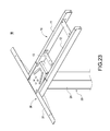
- FIG. 25 is a schematic view of the invention applied to a liftable table.
- the invention provides a liftable table foot frame 1 that is easily assembled as shown in FIGS. 1-4 , which includes a horizontal frame body 10 , a post 20 , a side wing 30 and a linking mechanism 40 .
- the horizontal frame body 10 includes a first horizontal rod 11 , a second horizontal rod 12 and a plurality of short rods 13 .
- the first horizontal rod 11 and the second horizontal rod 12 are parallelly arranged at an interval and are combined into the horizontal frame body 10 by being connected by the short rods 13 .
- the first horizontal rod 11 is formed with an arced trough 111 and a rectangular hole 112 .
- a guiding trough 113 is formed outside the rectangular hole 112 of the first horizontal rod 11 .
- a side of the second horizontal rod 12 which corresponds to the first horizontal rod 11 , is formed with an arced trough, a rectangular hole and a guiding trough (not shown) as those of the first horizontal rod 11 .
- the post 20 is pivotally connected to the horizontal frame body 10 .
- the post 20 includes a telescopic rod 21 and a base plate 22 connected to an end of the telescopic rod 21 .
- the base plate 22 in this embodiment is approximately of, but not limited to, a U-shape.
- a threaded hole 221 is provided at each of two opposite sides of the base plate 22 .
- Each of outsides of two opposite sides of the base plate 22 is connected with a bolt 222 .
- the post 20 is embedded into the arced trough 111 through the bolts 222 so that the post 20 can rotate relative to the first horizontal rod 11 and the second horizontal rod 12 .
- the side wing 30 includes a plate body 31 and two inserting blocks 32 connected at a middle of the plate body 31 .
- the plate body 31 in this embodiment is a longitudinal right-angled plate.
- a rod body 33 is connected between the two inserting blocks 32 .
- the linking mechanism 40 in this embodiment includes a first connecting member 41 and a second connecting member 42 .
- a top end and a bottom end of the first connecting member 41 are formed with a through hole 415 and a hook 416 , respectively.
- the first connecting member 41 is fastened to the base plate 22 by inserting a screw into the through hole 415 and screwing on to the threaded hole 221 .
- the first connecting member 41 is hooked on the rod body 33 through the hook 416 .
- the first connecting member 41 has a buffer portion for reducing stress deformation resulting from assembling.
- the buffer portion includes at least one bending section.
- the buffer portion in this embodiment includes a first bending section 411 , a second bending section 412 bendingly extending from the first bending section 411 , a third bending section 413 bendingly extending from the second bending section 412 and a fourth bending section 414 bendingly extending from the third bending section 413 .
- the through hole 415 is located in the first bending section 411 and the hook 416 is located at the fourth bending section 414 .
- the second bending section 412 is approximately of a U-shape.
- the second connecting member 42 has all features the same as those of the first connecting member 41 .
- the through holes 415 of the first connecting member 41 and the second connecting member 42 are passed through by a screw to be fastened to the threaded holes 221 of the base plate 22 .
- the first connecting member 41 and the second connecting member 42 are embedded into the arced trough 111 through the bolts 222 so that the linking mechanism 40 , the post 20 , and the horizontal frame body 10 are combined together.
- the bending sections 414 of the first connecting member 41 and the second connecting member 42 enter insides of the first horizontal rod 11 and second horizontal rod 12 through the rectangular hole 112 so that the hooks 416 are formed inside the first horizontal rod 11 and second horizontal rod 12 .
- the hooks 416 of the first connecting member 41 and the second connecting member 42 are hooked on the rod body 33 .
- the rod body 33 is embedded into the first horizontal rod 11 and second horizontal rod 12 along the guiding trough 113 to position the side wing 30 , the horizontal frame body 10 and the linking mechanism 40 .
- the post 20 When operating, the post 20 is rotated about the bolt 222 and downward turned out relative to the first horizontal rod 11 and second horizontal rod 12 away from the horizontal frame body 10 .
- the first connecting member 41 and the second connecting member 42 pull the inserting blocks 32 of the side wing 30 through the hooks 416 toward the first horizontal rod 11 and second horizontal rod 12 to abut, so that the horizontal frame body 10 , the post 20 and the side wing 30 can be rapidly positioned. Because the buffer portion can be flexibly deformed, the first connecting member 41 and the second connecting member 42 can be firmly fixed on each side of the base plate 22 .
- the liftable table foot frame that is easily assembled of the invention can also be implemented as this embodiment shown in the figures.
- the liftable table foot frame 1 A includes a horizontal frame body 10 , a post 20 , a side wing 30 and a linking mechanism 40 A.
- the horizontal frame body 10 includes a first horizontal rod 11 , a second horizontal rod 12 and a plurality of short rods 13 .
- the first horizontal rod 11 and the second horizontal rod 12 are parallelly arranged at an interval and are combined into the horizontal frame body 10 by being connected by the short rods 13 .
- the first horizontal rod 11 is formed with an inclined trough 111 A and a pivot hole 112 A formed at an end of the inclined trough 111 A.
- a side of the second horizontal rod 12 which corresponds to the first horizontal rod 11 , is formed with an inclined trough and a pivot hole (not shown) as those of the first horizontal rod 11 .
- the post 20 in this embodiment is pivotally connected to the first horizontal rod 11 and second horizontal rod 12 .
- the post 20 includes a telescopic rod 21 and a base plate 22 connected to an end of the telescopic rod 21 .
- the post 20 in this embodiment is pivotally connected to the first horizontal rod 11 and second horizontal rod 12 through the linking mechanism 40 A fixed on the base plate 22 .
- the side wing 30 includes a plate body 31 and two inserting blocks 32 .
- An engaging trough 321 A is formed in each of the inserting blocks 32 .
- the linking mechanism 40 A in this embodiment includes a first cam 41 A and a second cam 42 A.
- the first cam 41 A and the second cam 42 A are approximately of a water drop shape and separately connected to outsides of two opposite sides of the base plate 22 .
- the first cam 41 A and the second cam 42 A both pivotally connect to the first horizontal rod 11 and second horizontal rod 12 and connect to the inserting blocks 32 of the side wing 30 .
- each of the inserting blocks 32 is inserted into ends of the first horizontal rod 11 and second horizontal rod 12 and each of the engaging troughs 321 A is aligned with one of the pivot holes 112 A.
- the first cam 41 A and the second cam 42 A are separately inserted into the inclined troughs 111 A and positioned in the pivot holes 112 A.
- the post 20 When operating, the post 20 is rotated about the first cam 41 A and the second cam 42 A and downward turned out relative to the first horizontal rod 11 and second horizontal rod 12 away from the horizontal frame body 10 .
- the first cam 41 A and the second cam 42 A are separately engaged in each of the pivot holes 112 A and engaging troughs 321 A. Because of the water drop shape of the first cam 41 A and the second cam 42 A, the inserting blocks 32 of the side wing 30 are pulled toward the first horizontal rod 11 and second horizontal rod 12 to abut, so that the horizontal frame body 10 , the post 20 and the side wing 30 can be rapidly positioned.
- the liftable table foot frame 1 B of the embodiment includes a horizontal frame body 10 , a post 20 , a side wing 30 and a linking mechanism 40 B.
- the horizontal frame body 10 includes a first horizontal rod 11 , a second horizontal rod 12 and a plurality of short rods 13 .
- the first horizontal rod 11 and the second horizontal rod 12 are parallelly arranged at an interval and are combined into the horizontal frame body 10 by being connected by the short rods 13 .
- the first horizontal rod 11 is formed with a threaded hole 111 B and a guide trough 112 B.
- a side of the second horizontal rod 12 which corresponds to the first horizontal rod 11 , is formed with a threaded hole and a guide trough (not shown) as those of the first horizontal rod 11 .
- the post 20 is pivotally connected to the first horizontal rod 11 and second horizontal rod 12 .
- the post 20 includes a telescopic rod 21 and a base plate 22 connected to an end of the telescopic rod 21 .
- Each of two sides of the base plate 22 is formed with a passing hole 221 B corresponding to each other.
- the base plate 11 is pivotally connected to the first horizontal rod 11 and second horizontal rod 12 through bolts 222 separately passing the passing holes 221 B.
- the side wing 30 includes a plate body 31 and two inserting blocks 32 .
- a bar 321 B is formed on each of the inserting blocks 32 .
- the linking mechanism 40 B in this embodiment includes a first track trough 41 B and a second track trough 42 B.
- the first track trough 41 B and a second track trough 42 B are formed at two sides of the base plate 22 , which are away from the passing holes 221 B.
- each of the passing holes 221 B is inserted into by a bolt 222 to fasten the base plate 22 to the threaded holes 111 B.
- the inserting blocks 21 are separately inserted into ends of the first horizontal rod 11 and the second horizontal rod 12 .
- the bars 321 B are separately embedded into the guide troughs 112 B.
- the post 20 When operating, the post 20 is rotated about the screws and downward turned out relative to the first horizontal rod 11 and second horizontal rod 12 away from the horizontal frame body 10 .
- the first track trough 41 B and the second track trough 42 B are separately engaged with each of the bars 321 B.
- the inserting blocks 32 of the side wing 30 are pulled toward the first horizontal rod 11 and second horizontal rod 12 to abut, so that the horizontal frame body 10 , the post 20 and the side wing 30 can be rapidly positioned.
- the liftable table foot frame that is easily assembled of the invention may be coupled under a table board 8 to form an electrically liftable table.
Landscapes
- Engineering & Computer Science (AREA)
- General Engineering & Computer Science (AREA)
- Mechanical Engineering (AREA)
- Accommodation For Nursing Or Treatment Tables (AREA)
- Tables And Desks Characterized By Structural Shape (AREA)
- Furniture Connections (AREA)
Abstract
Description
Claims (12)
Priority Applications (1)
| Application Number | Priority Date | Filing Date | Title |
|---|---|---|---|
| US16/056,091 US10405646B2 (en) | 2017-10-26 | 2018-08-06 | Liftable table foot frame that is easily assembled |
Applications Claiming Priority (2)
| Application Number | Priority Date | Filing Date | Title |
|---|---|---|---|
| US201762577328P | 2017-10-26 | 2017-10-26 | |
| US16/056,091 US10405646B2 (en) | 2017-10-26 | 2018-08-06 | Liftable table foot frame that is easily assembled |
Publications (2)
| Publication Number | Publication Date |
|---|---|
| US20190125072A1 US20190125072A1 (en) | 2019-05-02 |
| US10405646B2 true US10405646B2 (en) | 2019-09-10 |
Family
ID=62950316
Family Applications (1)
| Application Number | Title | Priority Date | Filing Date |
|---|---|---|---|
| US16/056,091 Active US10405646B2 (en) | 2017-10-26 | 2018-08-06 | Liftable table foot frame that is easily assembled |
Country Status (7)
| Country | Link |
|---|---|
| US (1) | US10405646B2 (en) |
| JP (1) | JP6496847B1 (en) |
| KR (1) | KR102009786B1 (en) |
| CN (2) | CN109700174B (en) |
| DK (1) | DK179758B1 (en) |
| FI (1) | FI128776B (en) |
| TW (2) | TWM560241U (en) |
Cited By (3)
| Publication number | Priority date | Publication date | Assignee | Title |
|---|---|---|---|---|
| US11357320B2 (en) * | 2018-03-14 | 2022-06-14 | Linak A/S | Frame for a table |
| US20230210252A1 (en) * | 2020-09-02 | 2023-07-06 | Veyhl Gmbh | Table frame and table |
| US12588753B2 (en) | 2022-03-01 | 2026-03-31 | Zhejiang Jiecang Linear Motion Technology Co., Ltd. | Electric height adjustable desk |
Families Citing this family (10)
| Publication number | Priority date | Publication date | Assignee | Title |
|---|---|---|---|---|
| US11096481B2 (en) * | 2017-07-28 | 2021-08-24 | Varidesk, Llc | Motorized adjustable height table |
| TWM560241U (en) * | 2017-10-26 | 2018-05-21 | Timotion Technology Co Ltd | Easy-to-assemble lifting table stand |
| US11771216B2 (en) * | 2019-08-27 | 2023-10-03 | Ergotron, Inc. | Workstation including simplified leg attachment |
| CN111436746B (en) * | 2020-04-23 | 2024-11-12 | 常州市凯迪电器股份有限公司 | A quick-assembled desktop stand |
| CN212280392U (en) * | 2020-04-26 | 2021-01-05 | 德沃康科技集团有限公司 | Mounting bracket of lifting table |
| CN213820289U (en) * | 2020-11-10 | 2021-07-30 | 德沃康科技集团有限公司 | A folding table frame and folding table |
| US11490726B1 (en) * | 2021-07-01 | 2022-11-08 | Zhejiang Jiecang Linear Motion Technology Co., Ltd. | Folding table stand, folding table, and method for assembling the same |
| CN217390195U (en) * | 2021-11-10 | 2022-09-09 | 常州市凯迪电器股份有限公司 | Lifting table support with quick mounting structure and lifting table |
| TWI788178B (en) | 2022-01-04 | 2022-12-21 | 第一傳動科技股份有限公司 | Power-driven table, power-driven table stand and lightweight beam structure thereof |
| TWI790975B (en) * | 2022-06-06 | 2023-01-21 | 第一傳動科技股份有限公司 | Beam structure of electric table stand |
Citations (21)
| Publication number | Priority date | Publication date | Assignee | Title |
|---|---|---|---|---|
| US4064815A (en) * | 1976-07-19 | 1977-12-27 | Berco Industries | Table leg locking mechanism |
| US4444124A (en) * | 1981-10-26 | 1984-04-24 | Howe Furniture Corporation | Foldable trestle type table |
| US4561622A (en) | 1982-08-05 | 1985-12-31 | Eberhard Heinzel | Folding table catch |
| US4838180A (en) * | 1988-03-04 | 1989-06-13 | Ditto Sales, Inc. | Folding table leg apparatus |
| US5528997A (en) * | 1994-06-09 | 1996-06-25 | Kimball International, Inc. | Folding table leg mechanism |
| US5606922A (en) * | 1995-06-09 | 1997-03-04 | Johnson Industries, Inc. | Table leg latch mechanism |
| US5673633A (en) * | 1995-05-31 | 1997-10-07 | Pfister; Joel W. | Table leg system |
| US5913272A (en) * | 1998-06-19 | 1999-06-22 | Ditto Sales, Inc. | Folding table release latch apparatus |
| JP2000083740A (en) | 1998-09-09 | 2000-03-28 | Okuyama Seisakusho:Kk | Collapsible table |
| US20030116685A1 (en) | 2001-12-24 | 2003-06-26 | Jensen Jonathan K. | Folding leg system |
| EP1366688A1 (en) | 2002-05-31 | 2003-12-03 | Megkon B.V. | Piece of furniture |
| US20050235886A1 (en) * | 2004-04-27 | 2005-10-27 | Paul Koning | Folding leg latch assembly |
| US20080178778A1 (en) * | 2004-04-27 | 2008-07-31 | Paul Koning | Latch assembly with remote release |
| US20130104782A1 (en) * | 2011-10-27 | 2013-05-02 | Grant Rogers | Leg locking and folding mechanism for folding table |
| EP2926688A1 (en) | 2014-04-03 | 2015-10-07 | Timotion Technology Co., Ltd. | Collapsible power-driven table stand |
| TWM546736U (en) | 2017-05-26 | 2017-08-11 | Modernsolid industrial co ltd | Collapsible table |
| US20180110324A1 (en) * | 2016-10-20 | 2018-04-26 | Vitra Patente Ag | Height-adjustable frame with foldable leg elements |
| WO2018093323A1 (en) | 2016-11-17 | 2018-05-24 | Polstiernan Industri AB | A collapsible power-driven table stand, and a table comprising such a table stand |
| WO2018093324A1 (en) | 2016-11-17 | 2018-05-24 | Polstiernan Industri AB | A collapsible table stand, and a table comprising such a table stand |
| US20180242728A1 (en) | 2015-09-02 | 2018-08-30 | Kesseböhmer Produktions GmbH & Co. KG | Furniture frame for securing a foldable furniture pillar |
| US20190082823A1 (en) * | 2017-09-18 | 2019-03-21 | Fellowes, Inc. | Variable height platform system |
Family Cites Families (4)
| Publication number | Priority date | Publication date | Assignee | Title |
|---|---|---|---|---|
| CN203828340U (en) * | 2014-04-15 | 2014-09-17 | 王智勇 | Table leg frame |
| CN203776371U (en) * | 2014-04-15 | 2014-08-20 | 第一传动科技股份有限公司 | Easy-to-fold electric table stand |
| CN205093818U (en) * | 2015-10-28 | 2016-03-23 | 第一传动科技股份有限公司 | Table frame structure |
| TWM560241U (en) * | 2017-10-26 | 2018-05-21 | Timotion Technology Co Ltd | Easy-to-assemble lifting table stand |
-
2017
- 2017-11-21 TW TW106217283U patent/TWM560241U/en unknown
- 2017-11-21 TW TW106140372A patent/TWI711409B/en active
- 2017-11-27 CN CN201711206148.0A patent/CN109700174B/en active Active
- 2017-11-27 CN CN201721604981.6U patent/CN208597841U/en not_active Withdrawn - After Issue
- 2017-12-29 FI FI20176203A patent/FI128776B/en active IP Right Grant
- 2017-12-29 KR KR1020170183906A patent/KR102009786B1/en active Active
-
2018
- 2018-01-09 JP JP2018001087A patent/JP6496847B1/en active Active
- 2018-02-13 DK DKPA201870086A patent/DK179758B1/en active IP Right Grant
- 2018-08-06 US US16/056,091 patent/US10405646B2/en active Active
Patent Citations (23)
| Publication number | Priority date | Publication date | Assignee | Title |
|---|---|---|---|---|
| US4064815A (en) * | 1976-07-19 | 1977-12-27 | Berco Industries | Table leg locking mechanism |
| US4444124A (en) * | 1981-10-26 | 1984-04-24 | Howe Furniture Corporation | Foldable trestle type table |
| US4561622A (en) | 1982-08-05 | 1985-12-31 | Eberhard Heinzel | Folding table catch |
| US4838180A (en) * | 1988-03-04 | 1989-06-13 | Ditto Sales, Inc. | Folding table leg apparatus |
| US5528997A (en) * | 1994-06-09 | 1996-06-25 | Kimball International, Inc. | Folding table leg mechanism |
| US5673633A (en) * | 1995-05-31 | 1997-10-07 | Pfister; Joel W. | Table leg system |
| US5606922A (en) * | 1995-06-09 | 1997-03-04 | Johnson Industries, Inc. | Table leg latch mechanism |
| US5913272A (en) * | 1998-06-19 | 1999-06-22 | Ditto Sales, Inc. | Folding table release latch apparatus |
| JP2000083740A (en) | 1998-09-09 | 2000-03-28 | Okuyama Seisakusho:Kk | Collapsible table |
| US20030116685A1 (en) | 2001-12-24 | 2003-06-26 | Jensen Jonathan K. | Folding leg system |
| EP1366688A1 (en) | 2002-05-31 | 2003-12-03 | Megkon B.V. | Piece of furniture |
| US20050235886A1 (en) * | 2004-04-27 | 2005-10-27 | Paul Koning | Folding leg latch assembly |
| US20080178778A1 (en) * | 2004-04-27 | 2008-07-31 | Paul Koning | Latch assembly with remote release |
| US20130104782A1 (en) * | 2011-10-27 | 2013-05-02 | Grant Rogers | Leg locking and folding mechanism for folding table |
| EP2926688A1 (en) | 2014-04-03 | 2015-10-07 | Timotion Technology Co., Ltd. | Collapsible power-driven table stand |
| US20150282605A1 (en) * | 2014-04-03 | 2015-10-08 | Timotion Technology Co., Ltd. | Collapsible power-driven table stand |
| US20160037904A1 (en) | 2014-04-03 | 2016-02-11 | Timotion Technology Co., Ltd. | Collapsible power-driven table stand |
| US20180242728A1 (en) | 2015-09-02 | 2018-08-30 | Kesseböhmer Produktions GmbH & Co. KG | Furniture frame for securing a foldable furniture pillar |
| US20180110324A1 (en) * | 2016-10-20 | 2018-04-26 | Vitra Patente Ag | Height-adjustable frame with foldable leg elements |
| WO2018093323A1 (en) | 2016-11-17 | 2018-05-24 | Polstiernan Industri AB | A collapsible power-driven table stand, and a table comprising such a table stand |
| WO2018093324A1 (en) | 2016-11-17 | 2018-05-24 | Polstiernan Industri AB | A collapsible table stand, and a table comprising such a table stand |
| TWM546736U (en) | 2017-05-26 | 2017-08-11 | Modernsolid industrial co ltd | Collapsible table |
| US20190082823A1 (en) * | 2017-09-18 | 2019-03-21 | Fellowes, Inc. | Variable height platform system |
Non-Patent Citations (3)
| Title |
|---|
| Office Action dated Apr. 18, 2019 of the corresponding Korean patent application. |
| Office Action dated Nov. 2, 2018 of the corresponding Danish patent application No. PA201870086. |
| Office Action dated Nov. 9, 2018 of the corresponding Taiwan patent application. |
Cited By (4)
| Publication number | Priority date | Publication date | Assignee | Title |
|---|---|---|---|---|
| US11357320B2 (en) * | 2018-03-14 | 2022-06-14 | Linak A/S | Frame for a table |
| US11839301B2 (en) | 2018-03-14 | 2023-12-12 | Linak A/S | Frame for a table |
| US20230210252A1 (en) * | 2020-09-02 | 2023-07-06 | Veyhl Gmbh | Table frame and table |
| US12588753B2 (en) | 2022-03-01 | 2026-03-31 | Zhejiang Jiecang Linear Motion Technology Co., Ltd. | Electric height adjustable desk |
Also Published As
| Publication number | Publication date |
|---|---|
| TWM560241U (en) | 2018-05-21 |
| KR102009786B1 (en) | 2019-10-21 |
| JP2019076685A (en) | 2019-05-23 |
| KR20190046586A (en) | 2019-05-07 |
| TWI711409B (en) | 2020-12-01 |
| CN208597841U (en) | 2019-03-15 |
| US20190125072A1 (en) | 2019-05-02 |
| DK201870086A1 (en) | 2019-05-01 |
| CN109700174B (en) | 2021-12-10 |
| TW201916834A (en) | 2019-05-01 |
| FI20176203A1 (en) | 2019-04-27 |
| FI128776B (en) | 2020-11-30 |
| DK179758B1 (en) | 2019-05-08 |
| JP6496847B1 (en) | 2019-04-10 |
| CN109700174A (en) | 2019-05-03 |
Similar Documents
| Publication | Publication Date | Title |
|---|---|---|
| US10405646B2 (en) | Liftable table foot frame that is easily assembled | |
| US20230210254A1 (en) | Electric table, leg stand and lightweight beam structure thereof | |
| CN107061437A (en) | Module connection structure and LED display | |
| WO2016070636A1 (en) | Flexible led module, circular led module and wave-shaped led module | |
| CN202252723U (en) | Flat-panel TV wall hanger with pitching function | |
| CN204378319U (en) | A kind of plug-in type desk | |
| CN117881134B (en) | Quick disassembly and assembly structure of electrical unit and electric table | |
| CN107842539A (en) | A kind of fastening structure of clothes airing machine host panel | |
| CN205625342U (en) | Telescopic bed frame | |
| CN201202710Y (en) | Frame connecting apparatus of detachable panel screen | |
| CN205825688U (en) | A kind of column of medical material dry in the sun plate | |
| TWM626132U (en) | Electric table, electric table stand and lightweight beam structure thereof | |
| CN209837304U (en) | Steel construction assembled wallboard | |
| CN208692708U (en) | A kind of children guard bar | |
| CN206418857U (en) | A kind of folding tent support articulated structure | |
| CN218088486U (en) | Household elevator car wall | |
| CN207898266U (en) | A kind of seat chair back linkage chair | |
| CN206329580U (en) | The movably arranged device of back rest supports column jecket | |
| KR20120026891A (en) | The stand which used this frame andframe structure for stand which had combining holes | |
| CN204983512U (en) | Universal supporting component of decorative cover | |
| CN209653720U (en) | Guide adjustment upper wheel for a sliding door | |
| CN220608215U (en) | Combined toilet armrest | |
| DE20301199U1 (en) | Light bed frame with support frame for the installation of rehabilitation devices | |
| CN209331513U (en) | Fast Installation bedstead | |
| CN209595268U (en) | A kind of height-adjustable bedstead support leg and beddo |
Legal Events
| Date | Code | Title | Description |
|---|---|---|---|
| AS | Assignment |
Owner name: TIMOTION TECHNOLOGY CO., LTD., TAIWAN Free format text: ASSIGNMENT OF ASSIGNORS INTEREST;ASSIGNORS:TSENG, KUAN-SHU;WU, CHOU-HSIN;LEE, TSUNG-LING;SIGNING DATES FROM 20180704 TO 20180710;REEL/FRAME:046565/0351 |
|
| FEPP | Fee payment procedure |
Free format text: ENTITY STATUS SET TO UNDISCOUNTED (ORIGINAL EVENT CODE: BIG.); ENTITY STATUS OF PATENT OWNER: SMALL ENTITY |
|
| FEPP | Fee payment procedure |
Free format text: ENTITY STATUS SET TO SMALL (ORIGINAL EVENT CODE: SMAL); ENTITY STATUS OF PATENT OWNER: SMALL ENTITY |
|
| STPP | Information on status: patent application and granting procedure in general |
Free format text: NON FINAL ACTION MAILED |
|
| STPP | Information on status: patent application and granting procedure in general |
Free format text: RESPONSE TO NON-FINAL OFFICE ACTION ENTERED AND FORWARDED TO EXAMINER |
|
| STPP | Information on status: patent application and granting procedure in general |
Free format text: PUBLICATIONS -- ISSUE FEE PAYMENT RECEIVED |
|
| STPP | Information on status: patent application and granting procedure in general |
Free format text: PUBLICATIONS -- ISSUE FEE PAYMENT VERIFIED |
|
| STCF | Information on status: patent grant |
Free format text: PATENTED CASE |
|
| MAFP | Maintenance fee payment |
Free format text: PAYMENT OF MAINTENANCE FEE, 4TH YR, SMALL ENTITY (ORIGINAL EVENT CODE: M2551); ENTITY STATUS OF PATENT OWNER: SMALL ENTITY Year of fee payment: 4 |