US10401235B2 - Thermal sensor placement for hotspot interpolation - Google Patents
Thermal sensor placement for hotspot interpolation Download PDFInfo
- Publication number
- US10401235B2 US10401235B2 US14/852,350 US201514852350A US10401235B2 US 10401235 B2 US10401235 B2 US 10401235B2 US 201514852350 A US201514852350 A US 201514852350A US 10401235 B2 US10401235 B2 US 10401235B2
- Authority
- US
- United States
- Prior art keywords
- temperature
- thermal sensors
- hotspot
- chip
- model
- Prior art date
- Legal status (The legal status is an assumption and is not a legal conclusion. Google has not performed a legal analysis and makes no representation as to the accuracy of the status listed.)
- Active, expires
Links
Images


Classifications
-
- G—PHYSICS
- G01—MEASURING; TESTING
- G01K—MEASURING TEMPERATURE; MEASURING QUANTITY OF HEAT; THERMALLY-SENSITIVE ELEMENTS NOT OTHERWISE PROVIDED FOR
- G01K13/00—Thermometers specially adapted for specific purposes
-
- G—PHYSICS
- G05—CONTROLLING; REGULATING
- G05B—CONTROL OR REGULATING SYSTEMS IN GENERAL; FUNCTIONAL ELEMENTS OF SUCH SYSTEMS; MONITORING OR TESTING ARRANGEMENTS FOR SUCH SYSTEMS OR ELEMENTS
- G05B15/00—Systems controlled by a computer
- G05B15/02—Systems controlled by a computer electric
-
- G—PHYSICS
- G06—COMPUTING OR CALCULATING; COUNTING
- G06F—ELECTRIC DIGITAL DATA PROCESSING
- G06F1/00—Details not covered by groups G06F3/00 - G06F13/00 and G06F21/00
- G06F1/04—Generating or distributing clock signals or signals derived directly therefrom
-
- G—PHYSICS
- G06—COMPUTING OR CALCULATING; COUNTING
- G06F—ELECTRIC DIGITAL DATA PROCESSING
- G06F1/00—Details not covered by groups G06F3/00 - G06F13/00 and G06F21/00
- G06F1/16—Constructional details or arrangements
- G06F1/20—Cooling means
- G06F1/206—Cooling means comprising thermal management
-
- G—PHYSICS
- G06—COMPUTING OR CALCULATING; COUNTING
- G06F—ELECTRIC DIGITAL DATA PROCESSING
- G06F1/00—Details not covered by groups G06F3/00 - G06F13/00 and G06F21/00
- G06F1/26—Power supply means, e.g. regulation thereof
- G06F1/32—Means for saving power
- G06F1/3203—Power management, i.e. event-based initiation of a power-saving mode
- G06F1/3206—Monitoring of events, devices or parameters that trigger a change in power modality
-
- G—PHYSICS
- G06—COMPUTING OR CALCULATING; COUNTING
- G06F—ELECTRIC DIGITAL DATA PROCESSING
- G06F11/00—Error detection; Error correction; Monitoring
- G06F11/30—Monitoring
- G06F11/3058—Monitoring arrangements for monitoring environmental properties or parameters of the computing system or of the computing system component, e.g. monitoring of power, currents, temperature, humidity, position, vibrations
-
- G—PHYSICS
- G06—COMPUTING OR CALCULATING; COUNTING
- G06F—ELECTRIC DIGITAL DATA PROCESSING
- G06F11/00—Error detection; Error correction; Monitoring
- G06F11/30—Monitoring
- G06F11/3089—Monitoring arrangements determined by the means or processing involved in sensing the monitored data, e.g. interfaces, connectors, sensors, probes, agents
- G06F11/3093—Configuration details thereof, e.g. installation, enabling, spatial arrangement of the probes
-
- G—PHYSICS
- G06—COMPUTING OR CALCULATING; COUNTING
- G06F—ELECTRIC DIGITAL DATA PROCESSING
- G06F1/00—Details not covered by groups G06F3/00 - G06F13/00 and G06F21/00
- G06F1/26—Power supply means, e.g. regulation thereof
- G06F1/32—Means for saving power
- G06F1/3203—Power management, i.e. event-based initiation of a power-saving mode
- G06F1/3234—Power saving characterised by the action undertaken
- G06F1/324—Power saving characterised by the action undertaken by lowering clock frequency
-
- G—PHYSICS
- G06—COMPUTING OR CALCULATING; COUNTING
- G06F—ELECTRIC DIGITAL DATA PROCESSING
- G06F1/00—Details not covered by groups G06F3/00 - G06F13/00 and G06F21/00
- G06F1/26—Power supply means, e.g. regulation thereof
- G06F1/32—Means for saving power
- G06F1/3203—Power management, i.e. event-based initiation of a power-saving mode
- G06F1/3234—Power saving characterised by the action undertaken
- G06F1/3296—Power saving characterised by the action undertaken by lowering the supply or operating voltage
-
- G—PHYSICS
- G06—COMPUTING OR CALCULATING; COUNTING
- G06F—ELECTRIC DIGITAL DATA PROCESSING
- G06F2201/00—Indexing scheme relating to error detection, to error correction, and to monitoring
- G06F2201/81—Threshold
-
- Y—GENERAL TAGGING OF NEW TECHNOLOGICAL DEVELOPMENTS; GENERAL TAGGING OF CROSS-SECTIONAL TECHNOLOGIES SPANNING OVER SEVERAL SECTIONS OF THE IPC; TECHNICAL SUBJECTS COVERED BY FORMER USPC CROSS-REFERENCE ART COLLECTIONS [XRACs] AND DIGESTS
- Y02—TECHNOLOGIES OR APPLICATIONS FOR MITIGATION OR ADAPTATION AGAINST CLIMATE CHANGE
- Y02D—CLIMATE CHANGE MITIGATION TECHNOLOGIES IN INFORMATION AND COMMUNICATION TECHNOLOGIES [ICT], I.E. INFORMATION AND COMMUNICATION TECHNOLOGIES AIMING AT THE REDUCTION OF THEIR OWN ENERGY USE
- Y02D10/00—Energy efficient computing, e.g. low power processors, power management or thermal management
-
- Y02D10/126—
-
- Y02D10/16—
Definitions
- aspects of the present disclosure relate generally to temperature sensing, and more particularly, to estimating a hotspot temperature.
- thermal sensors may be integrated on a chip to monitor temperature at various locations on the chip. Temperature readings from the thermal sensors may be input to a temperature manager that manages blocks (e.g., central processing units (CPUs)) on the chip based on the temperature readings to prevent excessive power leakage and/or thermal runaway. Thermal runaway occurs when increases in temperature cause increases in leakage power, which, in turn, cause further increases in temperature. This positive feedback can cause the temperature of the chip to rapidly rise, potentially damaging the chip.
- a temperature manager that manages blocks (e.g., central processing units (CPUs)) on the chip based on the temperature readings to prevent excessive power leakage and/or thermal runaway. Thermal runaway occurs when increases in temperature cause increases in leakage power, which, in turn, cause further increases in temperature. This positive feedback can cause the temperature of the chip to rapidly rise, potentially damaging the chip.
- blocks e.g., central processing units (CPUs)
- a temperature management system comprises a plurality of thermal sensors at different locations on a chip, and a temperature manager.
- the temperature manager is configured to receive a plurality of temperature readings from the thermal sensors, to fit a quadratic temperature model to the received temperature readings, and to estimate a hotspot temperature on the chip using the fitted quadratic temperature model.
- a second aspect relates to a method for managing temperature.
- the method comprises receiving a plurality of temperature readings from a plurality of thermal sensors, wherein the thermal sensors are at different locations on a chip.
- the method also comprises fitting a quadratic temperature model to the received temperature readings, and estimating a hotspot temperature on the chip using the fitted quadratic temperature model.
- a third aspect relates to an apparatus for managing temperature.
- the apparatus comprises means for receiving a plurality of temperature readings from a plurality of thermal sensors, wherein the thermal sensors are at different locations on a chip.
- the apparatus also comprises means for fitting a quadratic temperature model to the received temperature readings, and means for estimating a hotspot temperature on the chip using the fitted quadratic temperature model.
- a fourth aspects relates to a computer-readable medium comprising instructions stored thereon. When executed by a processor, the instructions cause the processor to receive a plurality of temperature readings from a plurality of thermal sensors, wherein the thermal sensors are at different locations on a chip, to fit a quadratic temperature model to the received temperature readings, and to estimate a hotspot temperature on the chip using the fitted quadratic temperature model.
- the one or more embodiments comprise the features hereinafter fully described and particularly pointed out in the claims.
- the following description and the annexed drawings set forth in detail certain illustrative aspects of the one or more embodiments. These aspects are indicative, however, of but a few of the various ways in which the principles of various embodiments may be employed and the described embodiments are intended to include all such aspects and their equivalents.
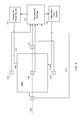
- FIG. 1 shows an exemplary temperature management system according to certain aspects of the present disclosure.
- FIG. 2 shows an exemplary temperature management system comprising thermal sensors placed on opposite sides of a CPU according to certain aspects of the present disclosure.
- FIG. 3 is a plot illustrating an exemplary temperature curve according to certain aspects of the present disclosure.
- FIG. 4 shows an exemplary temperature management system comprising thermal sensors placed on opposite sides of a CPU and a thermal sensor placed inside the CPU according to certain aspects of the present disclosure.
- FIG. 5 shows an exemplary temperature management system comprising thermal sensors placed on each side of a CPU according to certain aspects of the present disclosure.
- FIG. 6 shows an exemplary temperature management system comprising a thermal sensor placed on each side of a CPU and a thermal sensor placed inside the CPU according to certain aspects of the present disclosure.
- FIG. 7 shows an exemplary temperature management system comprising thermal sensors placed on each side and each corner of a CPU according to certain aspects of the present disclosure.
- FIG. 8 shows an exemplary temperature management system comprising a thermal sensor placed on each side and each corner of a CPU and a thermal sensor placed inside the CPU according to certain aspects of the present disclosure.
- FIG. 9 shows an exemplary temperature management system comprising thermal sensors arranged in a first configuration for managing temperature for two CPUs according to certain aspects of the present disclosure.
- FIG. 10 shows an exemplary temperature management system comprising thermal sensors arranged in a second configuration for managing temperature for two CPUs according to certain aspects of the present disclosure.
- FIG. 11 is a flowchart illustrating exemplary operations of a temperature manager according to certain aspects of the present disclosure.
- FIG. 12A is a flowchart of a method for managing temperature according to certain aspects of the present disclosure.
- FIG. 12B is a flowchart of additional optional steps that may be performed in the method for managing temperature according to certain aspects of the present disclosure.
- Thermal sensors may be integrated on a chip to monitor temperature at various locations on the chip. Temperature readings from the thermal sensors may be input to a temperature manager that manages blocks (e.g., central processing units (CPUs)) on the chip based on the temperature readings to prevent excessive power leakage and/or thermal runaway. For example, when a temperature reading reaches a temperature threshold, the temperature manager may take steps to reduce the temperature such as throttling back (reducing) the operating frequency of a CPU. This reduces the temperature by reducing the dynamic power dissipation of the CPU.
- blocks e.g., central processing units (CPUs)
- CPUs central processing units
- FIG. 1 shows an exemplary temperature management system according to certain aspects of the present disclosure.
- the temperature management system may comprise one or more thermal sensors 110 , a temperature manager 120 , an adjustable clock source 140 , and an adjustable power source 150 .
- the thermal sensor 110 may be configured to measure temperature within a CPU 130 or other type of circuit, and output corresponding temperature readings to the temperature manager 120 .
- the thermal sensor 110 may be integrated in the CPU 130 , as shown in FIG. 1 .
- the adjustable clock source 140 is configured to generate a clock signal for the CPU 130 , and to adjust the frequency of the clock signal under the control of the temperature manager 120 .
- the clock signal is output to the CPU 130 , which the CPU 130 may use for switching (toggling) transistors in the CPU 130 .
- the frequency of the clock signal may correspond to an operating frequency of the CPU 130 .
- the temperature manager 120 can adjust (scale) the operating frequency of the CPU 130 by adjusting the frequency of the clock signal output by the clock source 140 .
- the adjustable power source 150 is configured to provide an adjustable supply voltage (denoted “Vdd”) to the CPU 130 , and to adjust the supply voltage Vdd under the control of the temperature manager 120 .
- the power source 150 may comprise a power management integrated circuit (PMIC).
- the CPU 130 may use the supply voltage Vdd to power devices (e.g., transistors) in the CPU 130 .
- the temperature manager 120 can adjust (scale) the supply voltage of the CPU 130 by adjusting the supply voltage Vdd provided to the CPU 130 from the power source 150 .
- the temperature manager 120 monitors the temperature of the CPU 130 using the temperature readings from the thermal sensor 110 . If the temperature rises above a temperature threshold, the temperature manager 120 may initiate temperature mitigation, in which the temperature manager 120 takes action to reduce the temperature of the CPU 130 .
- the temperature manager 120 may reduce the temperature by reducing the operating frequency of the CPU 130 , reducing the supply voltage Vdd, or both. Reducing the operating frequency, the supply voltage Vdd, or both reduces the temperature by reducing the dynamic power dissipation of the CPU 130 , which is approximately proportional to the operating frequency and the square of the supply voltage Vdd.
- thermal sensors are placed as close as possible to one or more thermal hotspots on a chip.
- a “hotspot” is a hottest spot in a given area of the chip at a given time.
- the area may be the area of a CPU on the chip, the area of another block (e.g., modem, a memory, a processor, etc.) on the chip, the area of the entire chip, etc.
- a problem with the conventional approach is that a hotspot typically occurs in a very active and densely populated region of the chip (e.g., at or near the center of a CPU on the chip). Therefore, placing a thermal sensor near the hotspot may interference with the design of the chip and negatively impact chip performance. Also, the hotspot may move within the chip over time (e.g., depending on use case), making it difficult to locate the hotspot and get an accurate temperature measurement of the hotspot.
- a margin needs to be budgeted into a temperature reading from a thermal sensor to account for the worst case difference between the temperature reading and the temperature of the hotspot. For example, if the temperature manager 120 is configured to initiate temperature mitigation when the hotspot temperature reaches 90 degrees Celsius, the temperature manager 120 may initiate temperature mitigation when a temperature reading from the thermal sensor reaches 75 degrees Celsius. In this example, a 15 degree margin is budgeted into the temperature reading.
- a problem with this approach is that the difference between the temperature reading and the hotspot temperature may be less than the worst case difference in most cases. As a result, the temperature manager 120 may initiate temperature mitigation while the hotspot temperature is still below 90 degrees Celsius. Initiating temperature mitigation too soon unnecessarily reduces chip performance. This is because temperature mitigation typically may involve reducing the operating frequency of a CPU on the chip, which lowers the performance (e.g., processing speed) of the CPU.
- Embodiments of the present disclosure enable a temperature manager to estimate the temperature of a hotspot (hotspot temperature) on a chip without requiring that a thermal sensor be placed at the hotspot. Instead of placing a single thermal sensor at the hotspot, several thermal sensors may be placed around the hotspot.
- the temperature manager receives temperature readings from the sensors, and fits a temperature model of the chip to the temperature readings. After fitting the temperature model to the temperature readings, the temperature manager may use the temperature model to estimate the hotspot temperature on the chip, as discussed further below.
- an advantage of placing the sensors away from the hotspot is that there is typically a large amount of open space (e.g., filler area) around the CPU. This allows the sensors to be placed away from critical paths in the CPU, minimizing interference with operations of the CPU.
- FIG. 2 shows a temperature management system according to certain aspects of the present disclosure.
- the temperature management system comprises thermal sensors 210 , 212 , 214 and 216 placed outside the CPU 130 . More particularly, the temperature management system includes first and second sensors 210 and 212 located on one side of the CPU 130 , and third and fourth sensors 214 and 216 located on the opposite side of the CPU 130 .
- the thermal sensors 210 , 212 , 214 and 216 are approximately aligned along a line 218 intersecting the CPU 130 , as shown in FIG. 2 .
- the line 218 may be positioned so that the line 218 intersects an estimated hotspot location in the CPU 130 .
- the line 218 may be positioned to intersect the center of the CPU 130 (as shown in the example in FIG. 2 ) if the hotspot is expected to occur at or near the center of the CPU 130 .
- each of the thermal sensors 210 , 212 , 214 and 216 measures temperature at its location, and sends the corresponding temperature readings to the temperature manager 220 .
- the temperature manager 220 may be configured to fit a temperature model of the chip to the temperature readings received from the thermal sensors. The fitted temperature model allows the temperature manager 220 to interpolate temperatures at locations between the thermal sensors, and therefore estimate the hotspot temperature in the CPU 130 , as discussed further below.
- FIG. 3 shows an exemplary plot of temperature along line 218 shown in FIG. 2 .
- the temperature readings from the thermal sensors 210 , 212 , 214 and 216 indicate the temperatures at the known locations of the thermal sensors 210 , 212 , 214 and 216 along line 218 (denoted x 0 , x 1 , x 2 and x 3 , respectively).
- the temperature manager 220 fits a temperature model to the temperature readings.
- the temperature model comprises a quadratic curve 310 that is fitted to the temperature readings from the thermal sensors using, for example, regression or another technique.
- the quadratic curve 310 provides a good estimate of temperature along line 218 since the temperature gradient of the chip (die) is approximately quadratic. As shown in FIG. 3 , the curve 310 is concave with a peak temperature T p located within the CPU 130 .
- the temperature manager 220 may estimate the hotspot temperature using the model.
- the temperature manager 220 may estimate the hotspot temperature by calculating the peak temperature T p on the curve 310 , and using the peak temperature T p as an estimate of the hotspot temperature.
- the peak temperature T p on the curve 310 occurs at location x p , which is within the CPU 130 .
- the peak temperature T p provides an accurate estimate of the hotspot temperature in the CPU 130 , assuming the hotspot is located on or near line 218 .
- the temperature manager 220 may use the estimated hotspot temperature to perform temperature management, as discussed further below.
- T(x 0 ) is the temperature reading at sensor location x 0 (e.g., location of the first sensor 210 )
- T(x 1 ) is the temperature reading at sensor location x 1 (e.g., location of the second sensor 212 )
- T(x 2 ) is the temperature reading at sensor location x 2 (e.g., location of the third sensor 214 )
- T(x 3 ) is the temperature reading at sensor location x 3 (e.g., location of the fourth sensor 216 ).
- the temperature manager 220 may solve for the coefficients a 0 , a 1 and a 2 of the temperature model using the temperatures readings from the thermal sensors based on equation (2), and therefore fit the temperature model to the temperature readings.
- the temperature manager 220 may determine coefficients a 0 , a 1 and a 2 for the curve 310 that minimize the errors between the curve 310 and the temperature readings (e.g., determine coefficients a 0 , a 1 and a 2 that best fit the curve 310 to the temperature readings).
- the temperature manager 220 may determine the location of the peak temperature according to the following equation:
- Equation (4) is derived by calculating the derivative of equation (1) with respect to x, setting the derivative equal to zero, and solving for x.
- the temperature manager 220 may determine the peak temperature by inputting the peak location x p and determined coefficients a 0 , a 1 and a 2 into equation (1), and solving for temperature.
- the temperature manager 220 may receive temperature readings from the thermal sensors on a periodic basis, and estimate the hotspot temperature each time the temperature manager 220 receives temperature readings from the thermal sensors, as discussed above. This allows the temperature manager 220 to monitor the hotspot temperature in the CPU 130 , and perform temperature management based on the monitored hotspot temperature. For example, the temperature manager 220 may initiate temperature mitigation when the monitored hotspot temperature reaches a temperature threshold to prevent the hotspot temperature from reaching or coming close to a critical temperature (e.g., a temperature at which thermal runaway is triggered). The temperature manager 220 may perform temperature mitigation by commanding the adjustable clock source 140 to reduce (scale down) the frequency of the CPU, commanding the adjustable power source 150 to reduce the supply voltage Vdd, or both.
- a critical temperature e.g., a temperature at which thermal runaway is triggered
- the temperature manager 220 is able to accurately estimate the hotspot temperature in the CPU 130 without requiring that a thermal sensor be located at or near the hotspot in the CPU 130 .
- the margin that needs to be built into the estimated hotspot temperature to account for differences between the estimated hotspot temperature and the actual hotspot temperature is reduced.
- the reduced margin allows the CPU to operate at higher speed for a longer period of time before thermal mitigation is initiated, thereby improving performance.
- the thermal manager 220 may estimate the hotspot temperature using three thermal sensors instead of four. This is because three temperature readings at three different sensor locations may be sufficient to determine the three coefficients in equation (1). In this example, one of the thermal sensors in FIG. 2 may be omitted.
- FIG. 2 shows an example in which all of the sensors are located outside the CPU 130 , it is to be appreciated that this need not be the case.
- one or more of the sensors may be placed at known locations within the CPU.
- the one or more sensors may be placed in non-critical areas of the CPU to reduce interference with operations of the CPU. This is possible because aspects of the present disclosure do not require that a temperature sensor be placed at the hotspot (typically located in a critical area of the CPU) to accurately estimate the hotspot temperature.
- FIG. 4 shows an example of a temperature management system comprising three thermal sensors 410 , 412 and 414 along line 218 .
- the temperature management system comprises two thermal sensors 410 and 414 located on opposite sides of the CPU 130 , and one thermal sensor 412 located within the CPU 130 .
- the thermal sensor 412 within the CPU 130 may be located in a non-critical area of the CPU to reduce interference with operations of the CPU, as discussed above.
- the temperature manager 220 may receive temperature readings from the three thermal sensors 410 , 412 and 414 and fit a temperature model of the chip (e.g., temperature model given by equation (1)) to the received temperature readings. This allows the temperature manager 220 to interpolate temperatures at locations between the thermal sensors.
- the temperature manager 220 may then estimate the hotspot temperature by determining a peak temperature using the fitted temperature model, as discussed above.
- FIG. 5 shows a temperature management system according to certain aspects of the present disclosure.
- the temperature management system comprises thermal sensors on all sides of the CPU 130 . More particularly, the temperature management system includes the first, second, third and fourth thermal sensors 210 , 212 , 214 and 216 shown in FIG. 2 .
- the temperature management system includes fifth and sixth thermal sensors 510 and 512 located on one side of the CPU 310 , and seventh and eighth thermal sensors 514 and 516 located on the opposite side of the CPU.
- the fifth, sixth, seventh and eight thermal sensors 510 , 512 , 514 and 516 are approximately aligned along a line 518 that intersects the CPU 130 and is approximately perpendicular to line 218 , as shown in FIG. 5 .
- each of the thermal sensors 210 , 212 , 214 , 216 , 510 , 512 , 514 and 516 measures temperature at its location, and sends the corresponding temperature readings to the temperature manager 220 .
- the temperature manager 220 fits a temperature model of the chip to the temperature readings, and uses the fitted temperature model to estimate the hotspot temperature of the CPU 130 .
- T(x,y) is temperature as a function of location x,y
- x is the location along the x-axis
- y is the location along the y-axis
- a 0 , a 1 , a 2 , a 3 , and a 4 are coefficients.
- line 218 may be aligned with the x-axis and line 518 may be aligned with the y-axis.
- the eight thermal sensors 210 , 212 , 214 , 216 , 510 , 512 , 514 and 516 around the CPU 130 provide the temperature manager 220 with temperature readings corresponding to eight different locations around the CPU 130 .
- the temperature manager 220 may solve for the five coefficients a 0 , a 1 , a 2 , a 3 , and a 4 of the temperature model using the temperature readings received from the thermal sensors and the known locations of the temperature sensors, and therefore fit the temperature model to the temperature readings from the thermal sensors.
- the fitted model allows the temperature manager 220 to interpolate temperatures within the CPU 130 .
- the temperature manager 220 may determine a peak temperature using the model, and use the determined peak temperature as an estimate of the hotspot temperature in the CPU 130 . The temperature manager 220 may then manage the temperature of the CPU 130 based on the estimated hotspot temperature, as discussed above.
- the temperature manager 220 may determine the peak temperature using any one of a variety of techniques.
- the temperature manager 220 may determine the peak temperature by computing the derivative of equation (5) in the x and y dimensions, setting the derivative to zero to find the peak location (location of the peak temperature), and inputting the peak location into equation (5) to determine the peak temperature.
- the temperature manager 220 may determine the peak temperature using an iterative peak-finding algorithm such as a gradient descent algorithm.
- the temperature manager 220 may determine the peak temperature by computing the temperature for each location in a discrete set of locations using the temperature model, and selecting the highest computed temperature. To reduce computational load, the set of locations may be reduced to locations that are more likely to be at or near a hotspot (e.g., locations at or near an area of high activity in the CPU 130 ).
- peak temperature is not necessarily the absolute peak temperature given by a temperature model.
- the temperature manager 220 may determine the peak temperature (highest temperature) given by the model for a discrete set of locations.
- the determined peak temperature may approximate the absolute peak temperature given by the model if the location corresponding to the absolute peak temperature is between locations in the set of locations.
- the thermal manager 220 may estimate the hotspot temperature based on equation (5) using fewer than eight sensors.
- FIG. 6 shows an example of a temperature management system comprising a thermal sensor on each side of the CPU 130 and one thermal sensor within the CPU 130 for a total of five thermal sensors. More particularly, the temperature management system comprises two thermal sensors 610 and 612 along line 218 , two thermal sensors 616 and 614 along line 518 , and one thermal sensor 618 located approximately at the intersection of lines 218 and 518 .
- the five thermal sensors 610 , 612 , 614 , 616 and 618 provide temperature readings corresponding to five different sensor locations, which may be sufficient to solve for the five coefficients a 0 , a 1 , a 2 , a 3 , and a 4 of the temperature model given by equation (5).
- the temperature manager 220 may receive temperature readings from the thermal sensors 610 , 612 , 614 , 616 and 618 , and fit a temperature model of the chip (e.g., temperature model given by equation (5)) to the received temperature readings. The temperature manager 220 may then estimate the hotspot temperature by determining a peak temperature using the fitted temperature model, as discussed above.
- a temperature model of the chip e.g., temperature model given by equation (5)
- thermal sensor 618 is located at approximately the center of the CPU 130 in the example in FIG. 6 , it is to be appreciated that this need not be the case.
- thermal sensor 618 may be moved to the left or right along line 218 to move the thermal sensor 618 away from the center of the CPU 130 .
- thermal sensors 614 and 616 may also be moved to the left or right so that thermal sensors 614 , 616 and 618 remain aligned along a vertical line.
- thermal sensor 618 may be moved up or down along line 518 to move thermal sensor 618 away from the center of the CPU 130 .
- thermal sensors 610 and 612 may also be moved up or down so that thermal sensors 610 , 612 and 618 remain aligned along a horizontal line.
- FIG. 7 shows a temperature management system according to certain aspects of the present disclosure.
- the temperature management system comprises sixteen thermal sensors around the CPU 130 . More particularly, the temperature management system includes the thermal sensors 210 , 212 , 214 , 216 , 510 , 512 , 514 and 516 shown in FIG. 5 .
- the temperature management system includes thermal sensors 710 , 712 , 714 and 716 align along a first diagonal line 718 , and thermal sensors 720 , 722 , 724 and 726 align along a second diagonal line 728 , as shown in FIG. 7 .
- the temperature manager 220 is not shown in FIG. 7 .
- each of the thermal sensors measures temperature at its location, and sends the corresponding temperature readings to the temperature manager 220 .
- the temperature manager 220 fits a temperature model of the chip to the temperature readings, and uses the fitted temperature model to estimate the hotspot temperature of the CPU 130 .
- T(x,y) is temperature as a function of location x,y
- x is the location along the x-axis
- y is the location along the y-axis
- a 0 , a 1 , a 2 , a 3 , a 4 , a 5 , a 6 , a 7 and a 8 are coefficients.
- line 218 may be aligned with the x-axis and line 518 may be aligned with the y-axis.
- the temperature manager 220 may solve for the coefficients a 0 , a 1 , a 2 , a 3 , a 4 , a 5 , a 6 , a 7 and a 8 of the temperature model using the temperature readings received from the thermal sensors and the known locations of the temperature sensors, and therefore fit the temperature model to the temperature readings from the thermal sensors.
- the temperature manager 220 may determine a peak temperature using the model, and use the determined peak temperature as an estimate of the hotspot temperature in the CPU 130 .
- the temperature manager 220 may determine the peak temperature using any of the techniques discussed above or other techniques.
- the temperature manager 220 may then manage the temperature of the CPU 130 based on the estimated hotspot temperature, as discussed above.
- the thermal manager 220 may estimate the hotspot temperature based on equation (6) using fewer than sixteen sensors.
- FIG. 8 shows an example of a temperature management system comprising a thermal sensor on each side of the CPU 130 , a thermal sensor at each corner of the CPU 130 , and one thermal sensor within the CPU 130 for a total of nine thermal sensors. More particularly, the temperature management system comprises two thermal sensors 812 and 820 along line 218 , two thermal sensors 816 and 824 along line 518 , two thermal sensors 814 and 822 along diagonal line 718 , two thermal sensors 810 and 818 along diagonal line 728 , and one thermal sensor 618 located approximately at the intersection of lines 218 , 518 , 718 and 728 .
- the nine thermal sensors 810 , 812 , 814 , 816 , 818 , 820 , 822 , 824 and 826 provide temperature readings corresponding to nine different sensor locations, which may be sufficient to solve for the nine coefficients a 0 , a 1 , a 2 , a 3 , and a 4 , a 5 , a 6 , a 7 and a 8 of the temperature model given by equation (6).
- the temperature manager 220 may receive temperature readings from the thermal sensors, and fit a temperature model of the chip (e.g., temperature model given by equation (6)) to the received temperature readings. The temperature manager 220 may then estimate the hotspot temperature by determining a peak temperature using fitted temperature model, as discussed above.
- a temperature model of the chip e.g., temperature model given by equation (6)
- aspects of the present disclosure enable a temperature manager to estimate the temperature of a hotspot on a chip using a temperature model that is fitted to temperature readings from thermal sensors at know locations on the chip.
- the temperature model is quadratic. This provides a good estimate of the temperature within a CPU on a chip since the temperature gradient of the chip (die) is approximately quadratic.
- the temperature manager 220 is not limited to one CPU, and may manage temperature for two or more CPUs (e.g., in a multi-core system).
- FIG. 9 shows an exemplary temperature management system configured to manage temperature for a first CPU 930 and a second CPU 970 according to certain aspects of the present disclosure.
- the temperature management system may comprise a temperature manager 935 , an adjustable clock source 940 , and an adjustable power source 950 .
- the temperature manage system further comprises a plurality of thermal sensors 912 , 914 , 916 , 918 and 920 aligned along a line 922 intersecting the first and second CPUs 930 and 970 . More particularly, the temperature manage system comprises a first thermal sensor 912 located on one side of the first CPU 930 , a second thermal sensor 914 located within the first CPU 930 , a third thermal sensor 918 located between the first and second CPUs 930 and 970 , a fourth thermal sensor located within the second CPU 970 , and a fifth thermal sensor 920 located on a side of the second CPU 970 that is opposite the first CPU 930 .
- Each of the thermal sensors is configured to measure temperature at its location, and send the corresponding thermal readings to the temperature manager 935 , as discussed further below.
- the adjustable clock source 940 is configured to generate a first clock signal (denoted “Clk 1 ”) for the first CPU 930 , a second clock signal (denoted “Clk 2 ”) for the second CPU 970 , and to independently adjust the frequencies of the first and second clocks signal under the control of the temperature manager 935 .
- the adjustable power source 950 is configured to provide a first supply voltage (denoted “Vdd 1 ”) to the first CPU 930 , a second supply voltage (denoted “Vdd 2 ”) to the second CPU 970 , and to independently adjust the first and second supply voltages Vdd 1 and Vdd 2 under the control of the temperature manager 935 .
- the temperature manager 935 may manage the temperature of the first CPU 930 by receiving temperature readings from the first, second and third thermal sensors 912 , 914 and 916 , and fitting a temperature model (e.g., temperature model given in equation (1)) to the received temperature readings. After fitting the temperature model, the temperature manager 935 may determine a peak temperature using the temperature model, and use the determined peak temperature as an estimate of the hotspot temperature in the first CPU 930 . The temperature manager 935 may then manage the temperature of the first CPU 930 based on the estimated hotspot temperature in the first CPU 930 . For example, if the estimated hotspot temperature in the first CPU 930 exceeds a temperature threshold, the temperature manager 935 may initiate temperature mitigation to reduce the temperature of the first CPU 930 . The temperature manager 935 may reduce the temperature by commanding the adjustable clock source 940 to reduce the frequency of the first clock signal Clk 1 , and/or commanding the adjustable power source 950 to reduce the first supply voltage Vdd 1 .
- a temperature model e.g
- the temperature manager 935 may manage the temperature of the second CPU 970 by receiving temperature readings from the third, fourth and fifth thermal sensors 916 , 918 and 920 , and fitting a temperature model (e.g., temperature model given in equation (1)) to the received temperature readings. After fitting the temperature model, the temperature manager 935 may determine a peak temperature using the temperature model, and use the determined peak temperature as an estimate of the hotspot temperature in the second CPU 970 . The temperature manager 935 may then manage the temperature of the second CPU 970 based on the estimated hotspot temperature in the second CPU 970 . For example, if the estimated hotspot temperature in the second CPU 970 exceeds a temperature threshold, the temperature manager 935 may initiate temperature mitigation to reduce the temperature of the second CPU 970 . The temperature manager 935 may reduce the temperature by commanding the adjustable clock source 940 to reduce the frequency of the second clock signal Clk 2 , and/or commanding the adjustable power source 950 to reduce the second supply voltage Vdd 2 .
- a temperature model e.g
- the temperature manager 930 uses temperature readings from the third thermal sensor 916 to manage temperature for both the first and second CPUs 930 and 970 .
- the third thermal sensor 916 is shared by the first and second CPUs.
- the present disclosure is not limited to this example.
- the temperature management system in FIG. 9 may be modified to include two thermal sensors between the first and second CPUs along line 922 , in which one of the two thermal sensors is located closer to the first CPU 930 and the other one of the two thermal sensors is located closer to the second CPU 970 .
- the temperature manager 930 may use temperature readings from the thermal sensor located closer to the first CPU 930 and thermal sensors 912 and 914 for the first CPU 930 , and use the thermal sensor located closer to the second CPU 970 and thermal sensors 918 and 920 for the second CPU 970 .
- FIG. 10 shows an exemplary temperature management system configured to manage temperature for the first CPU 930 and the second CPU 970 according to certain aspects of the present disclosure.
- the temperature manage system comprises a plurality of thermal sensors 1010 , 1012 , 1014 , 1016 and 1018 aligned along line 922 . More particularly, the temperature manage system comprises first and second thermal sensors 1010 and 1012 located on one side of the first CPU 930 , a third thermal sensor 1014 located between the first and second CPUs 930 and 970 , and fourth and fifth thermal sensors 1016 and 1018 located on a side of the second CPU 970 that is opposite the first CPU 930 . Each of the thermal sensors is configured to measure temperature at its location, and send the corresponding thermal readings to the temperature manager 935 , as discussed further below.
- the temperature manager 935 may manage the temperature of the first CPU 930 by receiving temperature readings from the first, second and third thermal sensors 1010 , 1012 and 1014 , and fitting a temperature model (e.g., temperature model given in equation (1)) to the received temperature readings. After fitting the temperature model, the temperature manager 935 may determine a peak temperature using the temperature model, and use the determined peak temperature as an estimate of the hotspot temperature in the first CPU 930 . The temperature manager 935 may then manage the temperature of the first CPU 930 based on the estimated hotspot temperature in the first CPU 930 , as discussed above.
- a temperature model e.g., temperature model given in equation (1)
- the temperature manager 935 may manage the temperature of the second CPU 970 by receiving temperature readings from the third, fourth and fifth thermal sensors 1014 , 1016 and 1018 , and fitting a temperature model (e.g., temperature model given in equation (1)) to the received temperature readings. After fitting the temperature model, the temperature manager 935 may determine a peak temperature using the temperature model, and use the determined peak temperature as an estimate of the hotspot temperature in the second CPU 970 . The temperature manager 935 may then manage the temperature of the second CPU 970 based on the estimated hotspot temperature in the second CPU 970 , as discussed above.
- a temperature model e.g., temperature model given in equation (1)
- the temperature manager 220 or 935 may use one thermal sensor when the system is not close to temperature mitigation to conserve power. For example, the temperature manager 220 or 935 may initially receive temperature readings from a single thermal sensor, and compare each temperature reading to a low temperature threshold (e.g., 70 degrees Celsius). If a temperature reading is below the low threshold, then the temperature manager 220 or 935 may continue to only monitor the single thermal sensor. This may be based on the assumption that when the temperature readings from the single thermal sensor are relatively low (e.g., below 70 degrees Celsius), the system is not close to needing temperature mitigation. If a temperature reading from the single thermal sensor exceeds the low temperature threshold, then the temperature manager 220 or 935 may start monitoring multiple thermal sensors (e.g., all of the thermal sensors), and manage the temperature of the CPU as discussed above.
- a low temperature threshold e.g. 70 degrees Celsius
- the single thermal sensor may correspond to the thermal sensor that is expected to be closest to a hotspot.
- the single thermal sensor may correspond to thermal sensor 412 .
- the single thermal sensor may correspond to thermal sensor 212 or 214 (thermal sensors closest to the CPU 130 ).
- FIG. 11 is a flowchart illustrating exemplary operations 1100 of the temperature manager 220 or 935 according to certain aspects. Initially, the temperature manager 220 or 935 monitors temperature readings from a single thermal sensor, as discussed above.
- step 1110 the temperature manager determines whether a temperature reading from the single thermal sensors exceeds a low temperature threshold (denoted “Tm”). If the low temperature threshold is not exceeded, then the temperature manager continues to monitor temperature readings from the single sensor in step 1120 . Otherwise, the temperature manager proceeds to step 1130 .
- Tm low temperature threshold
- the temperature manager monitors temperature readings from multiple thermal sensors (e.g., thermal sensors around a CPU).
- the temperature manager determines whether the temperature readings from the multiple thermal sensors correspond to a concave curve (e.g., concave curve 310 ). If the temperature readings do not correspond to a concave curve (e.g., correspond to a convex curve), then the temperature manager performs temperature management based on the maximum temperature reading from the multiple thermal sensors in step 1150 . For example, the temperature manager may compare the maximum temperature reading to a first temperature threshold, and initiate temperature mitigation when the maximum temperature reading exceeds the first temperature threshold. If the temperature readings from the multiple thermal sensors correspond to a concave curve, then the temperature manager may proceed to step 1160 .
- the temperature manager takes temperature readings from the multiple thermal sensors.
- the temperature manager fits a temperature model to the temperature readings, and, in step 1180 , the temperature manager computes a peak temperature using the fitted temperature model.
- the temperature manager may use the peak temperature as an estimate of a hotspot temperature.
- the temperature manager may initiate temperature mitigation when the estimated hotspot temperature exceeds a second temperature threshold.
- the second temperature threshold may be higher than the first temperature threshold. This is because a larger budget may be built into the first temperature threshold assuming the estimated hotspot temperature provides a more accurate indication of the hotspot temperature than the maximum temperature reading.
- the temperature manager determines whether the temperature readings from the multiple thermal sensors correspond to a concave curve in step 1140 . For the example in FIG. 2 , the temperature manager may do this by comparing the temperature readings from thermal sensors 210 and 212 . If the temperature reading from thermal sensor 212 is higher than the temperature reading from thermal sensor 210 , then the temperature manager may determine a concave curve in step 1140 . If, on the other hand, the temperature reading from thermal sensor 212 is lower than the temperature reading from thermal sensor 210 , then the temperature manager may determine a convex curve in step 1140 .
- FIG. 12A is a flowchart illustrating a method 1200 for managing temperature according to an embodiment of the present disclosure.
- the method 1200 may be performed by the temperature manager 220 or 935 .
- a plurality of temperature readings are received from a plurality of thermal sensors, wherein the thermal sensors are at different locations on a chip.
- the thermal sensors may include thermal sensors located around a processor (e.g., CPU).
- the thermal sensors may also include one or more thermal sensors located within the processor.
- a quadratic temperature model is fitted to the received temperature readings.
- the quadratic temperature model may define a concave temperature curve (e.g., curve 310 ) that is fitted to the temperature readings.
- a hotspot temperature on the chip is estimated using the fitted quadratic temperature model.
- the hotspot temperature may be estimated by determining a peak temperature of the fitted temperature model.
- FIG. 12B is a flowchart illustrating additional optional steps that may be performed in the method 1200 for managing temperature according to certain aspects.
- the estimated hotspot temperature is compared to a temperature threshold.
- temperature mitigation is initiated if the estimated hotspot temperature exceeds the temperature threshold. The temperature mitigation may involve reducing the frequency of a clock signal, reducing a supply voltage, or both.
- any of the temperature management systems shown in FIGS. 2 and 4-10 may be used to manage temperature for a GPU, a modem, etc. by replacing the CPU with a GPU, a modem, etc.
- the temperature manager may be implemented with a general-purpose processor, a digital signal processor (DSP), an application specific integrated circuit (ASIC), a field programmable gate array (FPGA) or other programmable logic device, discrete hardware components, or any combination thereof designed to perform the functions described herein.
- a general-purpose processor may be a microprocessor, but in the alternative, the processor may be any conventional processor, controller, microcontroller, or state machine.
- a processor may perform the functions described herein by executing software comprising code for performing the functions.
- the software may be stored on a computer-readable storage medium, such as a RAM, a ROM, an EEPROM, an optical disk, and/or a magnetic disk.
Landscapes
- Engineering & Computer Science (AREA)
- Theoretical Computer Science (AREA)
- General Physics & Mathematics (AREA)
- Physics & Mathematics (AREA)
- General Engineering & Computer Science (AREA)
- Quality & Reliability (AREA)
- Human Computer Interaction (AREA)
- Computing Systems (AREA)
- Automation & Control Theory (AREA)
- Power Sources (AREA)
- Measuring Temperature Or Quantity Of Heat (AREA)
- Radiation Pyrometers (AREA)
- Semiconductor Integrated Circuits (AREA)
Abstract
Description
T(x)=a 0 +a 1 x+a 2 x 2 (Eq. 1)
where T(x) is temperature as a function of location x (e.g., along line 218), and a0, a1 and a2 are coefficients of the curve. Equation (1) can be written in matrix form for four temperature readings corresponding to four different sensor locations (e.g., along line 218) as follows:
where T(x0) is the temperature reading at sensor location x0 (e.g., location of the first sensor 210), T(x1) is the temperature reading at sensor location x1(e.g., location of the second sensor 212), T(x2) is the temperature reading at sensor location x2 (e.g., location of the third sensor 214), and T(x3) is the temperature reading at sensor location x3 (e.g., location of the fourth sensor 216). The
A=TX −1 (Eq. 3)
where A is a matrix comprising the coefficients being solved, T is a temperature matrix comprising the temperature readings at the sensor locations (e.g., four sensor locations), and X−1 is a pseudo inverse of a matrix comprising the sensor locations.
where xp is the location of the peak temperature. Equation (4) is derived by calculating the derivative of equation (1) with respect to x, setting the derivative equal to zero, and solving for x. After determining the peak location xp, the
T(x, y)=a 0 +a 1 x+a 2 x 2 +a 3 y+a 4 y 2 (Eq. 5)
where T(x,y) is temperature as a function of location x,y, x is the location along the x-axis, y is the location along the y-axis, and a0, a1, a2, a3, and a4 are coefficients. In this example,
T(x,y)=a 0 +a 1 x+a 2 x 2 +a 3 y+a 4 y 2 +a 5 xy+a 6 xy 2 +a 7 x 2 y+a 8 x 2 y 2 (Eq. 6)
where T(x,y) is temperature as a function of location x,y, x is the location along the x-axis, y is the location along the y-axis, and a0, a1, a2 , a3, a4 , a5, a6, a7 and a8 are coefficients. In this example,
Claims (19)
Priority Applications (7)
| Application Number | Priority Date | Filing Date | Title |
|---|---|---|---|
| US14/852,350 US10401235B2 (en) | 2015-09-11 | 2015-09-11 | Thermal sensor placement for hotspot interpolation |
| EP16763649.7A EP3347819B1 (en) | 2015-09-11 | 2016-08-29 | Thermal sensor placement for hotspot interpolation |
| CN201680051717.6A CN108027761B (en) | 2015-09-11 | 2016-08-29 | Thermal sensor placement for hotspot interpolation |
| PCT/US2016/049300 WO2017044341A1 (en) | 2015-09-11 | 2016-08-29 | Thermal sensor placement for hotspot interpolation |
| JP2018512942A JP2018532185A (en) | 2015-09-11 | 2016-08-29 | Thermal sensor placement for hot spot interpolation |
| TW105127745A TW201715324A (en) | 2015-09-11 | 2016-08-29 | Thermal sensor placement for hotspot interpolation |
| KR1020187010154A KR20180053343A (en) | 2015-09-11 | 2016-08-29 | Thermal sensor placement for hotspot interpolation |
Applications Claiming Priority (1)
| Application Number | Priority Date | Filing Date | Title |
|---|---|---|---|
| US14/852,350 US10401235B2 (en) | 2015-09-11 | 2015-09-11 | Thermal sensor placement for hotspot interpolation |
Publications (2)
| Publication Number | Publication Date |
|---|---|
| US20170074729A1 US20170074729A1 (en) | 2017-03-16 |
| US10401235B2 true US10401235B2 (en) | 2019-09-03 |
Family
ID=56896796
Family Applications (1)
| Application Number | Title | Priority Date | Filing Date |
|---|---|---|---|
| US14/852,350 Active 2037-08-08 US10401235B2 (en) | 2015-09-11 | 2015-09-11 | Thermal sensor placement for hotspot interpolation |
Country Status (7)
| Country | Link |
|---|---|
| US (1) | US10401235B2 (en) |
| EP (1) | EP3347819B1 (en) |
| JP (1) | JP2018532185A (en) |
| KR (1) | KR20180053343A (en) |
| CN (1) | CN108027761B (en) |
| TW (1) | TW201715324A (en) |
| WO (1) | WO2017044341A1 (en) |
Cited By (5)
| Publication number | Priority date | Publication date | Assignee | Title |
|---|---|---|---|---|
| US11442890B1 (en) | 2020-11-06 | 2022-09-13 | Amazon Technologies, Inc. | On-circuit data activity monitoring for a systolic array |
| US11520731B1 (en) * | 2020-11-06 | 2022-12-06 | Amazon Technologies, Inc. | Arbitrating throttling recommendations for a systolic array |
| US11822399B2 (en) | 2021-07-28 | 2023-11-21 | Apple Inc. | Temperature control loop for integrated circuit |
| US12197308B1 (en) | 2020-11-06 | 2025-01-14 | Amazon Technologies, Inc. | On-circuit utilization monitoring for a systolic array |
| US12210940B1 (en) | 2020-11-06 | 2025-01-28 | Amazon Technologies, Inc. | On-circuit activity monitoring for modifying integrated circuit processing |
Families Citing this family (13)
| Publication number | Priority date | Publication date | Assignee | Title |
|---|---|---|---|---|
| US20170248995A1 (en) * | 2016-02-29 | 2017-08-31 | GM Global Technology Operations LLC | Methods and systems for configurable temperature control of controller processors |
| US10705581B2 (en) * | 2017-03-24 | 2020-07-07 | Motorola Mobility Llc | Controlling device performance based on temperature differential |
| US10386899B2 (en) | 2017-08-08 | 2019-08-20 | GM Global Technology Operations LLC | Methods and systems for configurable temperature control of controller processors |
| JP2021083482A (en) * | 2019-11-25 | 2021-06-03 | 株式会社村田製作所 | Device for measuring inside of oral cavity and system for measuring inside of oral cavity |
| US11520369B2 (en) * | 2020-02-04 | 2022-12-06 | Qualcomm Incorporated | Clock instantaneous temperature-rate-of-change measurement |
| US11616841B2 (en) * | 2020-02-07 | 2023-03-28 | Taiwan Semiconductor Manufacturing Company Limited | Remote mapping of circuit speed variation due to process, voltage and temperature using a network of digital sensors |
| US12340299B2 (en) * | 2021-03-05 | 2025-06-24 | Qualcomm Incorporated | Sparsity-based neural network mapping to computing units in a system-on-chip |
| US12524059B2 (en) | 2022-01-06 | 2026-01-13 | Nvidia Corporation | Techniques for controlling computing performance for power-constrained multi-processor computing systems |
| US12253423B2 (en) * | 2022-02-25 | 2025-03-18 | Mellanox Technologies, Ltd. | Thermal sensor integration for system temperature management |
| US20240103591A1 (en) * | 2022-09-26 | 2024-03-28 | Ati Technologies Ulc | Power Management Using Temperature Gradient Information |
| WO2024191065A1 (en) * | 2023-03-16 | 2024-09-19 | 삼성전자 주식회사 | Electronic device, and operation method for electronic device |
| US20250004514A1 (en) * | 2023-06-30 | 2025-01-02 | Advanced Micro Devices, Inc | Adjustable Thermal Management |
| US20250181934A1 (en) * | 2023-12-01 | 2025-06-05 | Tejas Bahulkar | Thermal runtime prediction for electronic devices |
Citations (14)
| Publication number | Priority date | Publication date | Assignee | Title |
|---|---|---|---|---|
| US5015102A (en) | 1986-12-24 | 1991-05-14 | Terumo Kabushiki Kaisha | Method and apparatus for measuring temperature of a living body |
| GB2337121B (en) | 1998-05-09 | 2002-07-31 | Motorola Ltd | Temperature estimation arrangement and method |
| US20060013281A1 (en) * | 2004-07-16 | 2006-01-19 | International Business Machines Corporation | Method and system for real-time estimation and prediction of the thermal state of a microprocessor unit |
| US20070191993A1 (en) | 2006-02-16 | 2007-08-16 | Intel Corporation | Thermal management using an on-die thermal sensor |
| US20080092644A1 (en) * | 2006-10-18 | 2008-04-24 | Shimadzu Corporation | Thermal mass flow meter |
| US20080234953A1 (en) * | 2007-03-22 | 2008-09-25 | Ignowski James S | Power estimation for a semiconductor device |
| US7520669B2 (en) | 2004-06-04 | 2009-04-21 | Sony Computer Entertainment Inc. | Processor, processor system, temperature estimation device, information processing device, and temperature estimation method |
| US20100010741A1 (en) * | 2008-07-10 | 2010-01-14 | Lockheed Martin Missiles And Fire Control | Inertial measurement with an imaging sensor and a digitized map |
| US20100073068A1 (en) | 2008-09-22 | 2010-03-25 | Hanwoo Cho | Functional block level thermal control |
| US20110301777A1 (en) | 2010-06-04 | 2011-12-08 | Apple Inc. | Adjusting the thermal behavior of a computing system using indirect information about ambient temperature |
| US20130049708A1 (en) * | 2011-08-31 | 2013-02-28 | Honda Motor Co., Ltd. | Output control device of electric generator |
| US20130073245A1 (en) | 2011-09-16 | 2013-03-21 | Tata Consultancy Services Limited | Method and System for Real Time Monitoring, Prediction, Analysis and Display of Temperatures for Effective Thermal Management in a Data Center |
| US20130151191A1 (en) | 2011-12-13 | 2013-06-13 | Ecole Polytechnique Federale De Lausanne (Epfl) | Method to determine the distribution of temperature sensors, method to estimate the spatial and temporal thermal distribution and apparatus |
| US8972759B2 (en) * | 2012-06-29 | 2015-03-03 | Qualcomm Incorporated | Adaptive thermal management in a portable computing device including monitoring a temperature signal and holding a performance level during a penalty period |
-
2015
- 2015-09-11 US US14/852,350 patent/US10401235B2/en active Active
-
2016
- 2016-08-29 EP EP16763649.7A patent/EP3347819B1/en active Active
- 2016-08-29 KR KR1020187010154A patent/KR20180053343A/en not_active Withdrawn
- 2016-08-29 TW TW105127745A patent/TW201715324A/en unknown
- 2016-08-29 CN CN201680051717.6A patent/CN108027761B/en active Active
- 2016-08-29 WO PCT/US2016/049300 patent/WO2017044341A1/en not_active Ceased
- 2016-08-29 JP JP2018512942A patent/JP2018532185A/en active Pending
Patent Citations (15)
| Publication number | Priority date | Publication date | Assignee | Title |
|---|---|---|---|---|
| US5015102A (en) | 1986-12-24 | 1991-05-14 | Terumo Kabushiki Kaisha | Method and apparatus for measuring temperature of a living body |
| GB2337121B (en) | 1998-05-09 | 2002-07-31 | Motorola Ltd | Temperature estimation arrangement and method |
| US7520669B2 (en) | 2004-06-04 | 2009-04-21 | Sony Computer Entertainment Inc. | Processor, processor system, temperature estimation device, information processing device, and temperature estimation method |
| US7695188B2 (en) | 2004-07-16 | 2010-04-13 | International Business Machines Corporation | Method and system for real-time estimation and prediction of the thermal state of a microprocessor unit |
| US20060013281A1 (en) * | 2004-07-16 | 2006-01-19 | International Business Machines Corporation | Method and system for real-time estimation and prediction of the thermal state of a microprocessor unit |
| US20070191993A1 (en) | 2006-02-16 | 2007-08-16 | Intel Corporation | Thermal management using an on-die thermal sensor |
| US20080092644A1 (en) * | 2006-10-18 | 2008-04-24 | Shimadzu Corporation | Thermal mass flow meter |
| US20080234953A1 (en) * | 2007-03-22 | 2008-09-25 | Ignowski James S | Power estimation for a semiconductor device |
| US20100010741A1 (en) * | 2008-07-10 | 2010-01-14 | Lockheed Martin Missiles And Fire Control | Inertial measurement with an imaging sensor and a digitized map |
| US20100073068A1 (en) | 2008-09-22 | 2010-03-25 | Hanwoo Cho | Functional block level thermal control |
| US20110301777A1 (en) | 2010-06-04 | 2011-12-08 | Apple Inc. | Adjusting the thermal behavior of a computing system using indirect information about ambient temperature |
| US20130049708A1 (en) * | 2011-08-31 | 2013-02-28 | Honda Motor Co., Ltd. | Output control device of electric generator |
| US20130073245A1 (en) | 2011-09-16 | 2013-03-21 | Tata Consultancy Services Limited | Method and System for Real Time Monitoring, Prediction, Analysis and Display of Temperatures for Effective Thermal Management in a Data Center |
| US20130151191A1 (en) | 2011-12-13 | 2013-06-13 | Ecole Polytechnique Federale De Lausanne (Epfl) | Method to determine the distribution of temperature sensors, method to estimate the spatial and temporal thermal distribution and apparatus |
| US8972759B2 (en) * | 2012-06-29 | 2015-03-03 | Qualcomm Incorporated | Adaptive thermal management in a portable computing device including monitoring a temperature signal and holding a performance level during a penalty period |
Non-Patent Citations (2)
| Title |
|---|
| International Search Report and Written Opinion-PCT/US2016/049300-ISA/EPO-Nov. 23, 2016. |
| International Search Report and Written Opinion—PCT/US2016/049300—ISA/EPO—Nov. 23, 2016. |
Cited By (5)
| Publication number | Priority date | Publication date | Assignee | Title |
|---|---|---|---|---|
| US11442890B1 (en) | 2020-11-06 | 2022-09-13 | Amazon Technologies, Inc. | On-circuit data activity monitoring for a systolic array |
| US11520731B1 (en) * | 2020-11-06 | 2022-12-06 | Amazon Technologies, Inc. | Arbitrating throttling recommendations for a systolic array |
| US12197308B1 (en) | 2020-11-06 | 2025-01-14 | Amazon Technologies, Inc. | On-circuit utilization monitoring for a systolic array |
| US12210940B1 (en) | 2020-11-06 | 2025-01-28 | Amazon Technologies, Inc. | On-circuit activity monitoring for modifying integrated circuit processing |
| US11822399B2 (en) | 2021-07-28 | 2023-11-21 | Apple Inc. | Temperature control loop for integrated circuit |
Also Published As
| Publication number | Publication date |
|---|---|
| CN108027761A (en) | 2018-05-11 |
| EP3347819A1 (en) | 2018-07-18 |
| CN108027761B (en) | 2021-04-16 |
| US20170074729A1 (en) | 2017-03-16 |
| JP2018532185A (en) | 2018-11-01 |
| EP3347819B1 (en) | 2020-01-08 |
| KR20180053343A (en) | 2018-05-21 |
| TW201715324A (en) | 2017-05-01 |
| WO2017044341A1 (en) | 2017-03-16 |
Similar Documents
| Publication | Publication Date | Title |
|---|---|---|
| US10401235B2 (en) | Thermal sensor placement for hotspot interpolation | |
| US9971368B2 (en) | Accurate hotspot detection through temperature sensors | |
| US9590639B2 (en) | Semiconductor device and control method | |
| US11320877B2 (en) | Integrated circuit thermal throttling with workload adapted thermal sensor maximum temperature | |
| US8930724B2 (en) | Semiconductor device predictive dynamic thermal management | |
| US10275001B2 (en) | Thermal throttling of electronic devices | |
| US12123789B2 (en) | Method and device for temperature detection and thermal management based on power measurement | |
| JP4575333B2 (en) | Heat sensing system | |
| JP5638110B2 (en) | Thermal control apparatus and method | |
| US9483092B2 (en) | Performance state boost for multi-core integrated circuit | |
| TWI537719B (en) | Apparatus,system and method for tolerating induced thermal gradients in semiconductor devices | |
| US20080234953A1 (en) | Power estimation for a semiconductor device | |
| US8928394B2 (en) | Semiconductor integrated circuit and an operating method thereof, a timing verifying method for a semiconductor integrated circuit and a test method of a semiconductor integrated circuit | |
| US20150300888A1 (en) | Temperature prediction system and method thereof | |
| US20110077794A1 (en) | Sensor-Based Thermal Specification Enabling a Real-Time Metric for Compliance | |
| US20160061667A1 (en) | High accuracy, compact on-chip temperature sensor | |
| US9459314B1 (en) | Circuit and method for real-time monitoring of process, temperature, and voltage variations | |
| CN102681450B (en) | Method and equipment for controlling chip | |
| US20250167050A1 (en) | Local thermal sensing for system monitoring and control | |
| US10509450B1 (en) | Thermally protecting an access point device | |
| EP3422144B1 (en) | Semiconductor device and method of controlling semiconductor device | |
| Agarwal et al. | Redcooper: Hardware sensor enabled variability software testbed for lifetime energy constrained application | |
| US12332711B2 (en) | Systems and methods for mitigating peak current and improving overall performance | |
| KR20250130626A (en) | Power management using temperature gradient information | |
| US20190079121A1 (en) | Estimating a current in an smps |
Legal Events
| Date | Code | Title | Description |
|---|---|---|---|
| AS | Assignment |
Owner name: QUALCOMM INCORPORATED, CALIFORNIA Free format text: ASSIGNMENT OF ASSIGNORS INTEREST;ASSIGNORS:COUTTS, RYAN MICHAEL;MITTAL, RAJAT;SAEIDI, MEHDI;AND OTHERS;SIGNING DATES FROM 20151217 TO 20151228;REEL/FRAME:037425/0022 |
|
| STPP | Information on status: patent application and granting procedure in general |
Free format text: NON FINAL ACTION MAILED |
|
| STPP | Information on status: patent application and granting procedure in general |
Free format text: RESPONSE TO NON-FINAL OFFICE ACTION ENTERED AND FORWARDED TO EXAMINER |
|
| STPP | Information on status: patent application and granting procedure in general |
Free format text: NOTICE OF ALLOWANCE MAILED -- APPLICATION RECEIVED IN OFFICE OF PUBLICATIONS |
|
| STPP | Information on status: patent application and granting procedure in general |
Free format text: PUBLICATIONS -- ISSUE FEE PAYMENT VERIFIED |
|
| STCF | Information on status: patent grant |
Free format text: PATENTED CASE |
|
| MAFP | Maintenance fee payment |
Free format text: PAYMENT OF MAINTENANCE FEE, 4TH YEAR, LARGE ENTITY (ORIGINAL EVENT CODE: M1551); ENTITY STATUS OF PATENT OWNER: LARGE ENTITY Year of fee payment: 4 |