US10399397B2 - Device and method for inflating and repairing tires and other inflatables - Google Patents
Device and method for inflating and repairing tires and other inflatables Download PDFInfo
- Publication number
- US10399397B2 US10399397B2 US15/732,489 US201715732489A US10399397B2 US 10399397 B2 US10399397 B2 US 10399397B2 US 201715732489 A US201715732489 A US 201715732489A US 10399397 B2 US10399397 B2 US 10399397B2
- Authority
- US
- United States
- Prior art keywords
- insertion tube
- tire
- cartridge
- gas
- proximal end
- Prior art date
- Legal status (The legal status is an assumption and is not a legal conclusion. Google has not performed a legal analysis and makes no representation as to the accuracy of the status listed.)
- Active - Reinstated
Links
Images


Classifications
-
- B—PERFORMING OPERATIONS; TRANSPORTING
- B60—VEHICLES IN GENERAL
- B60C—VEHICLE TYRES; TYRE INFLATION; TYRE CHANGING; CONNECTING VALVES TO INFLATABLE ELASTIC BODIES IN GENERAL; DEVICES OR ARRANGEMENTS RELATED TO TYRES
- B60C25/00—Apparatus or tools adapted for mounting, removing or inspecting tyres
- B60C25/16—Tools for repairing damaged tyres
-
- B—PERFORMING OPERATIONS; TRANSPORTING
- B29—WORKING OF PLASTICS; WORKING OF SUBSTANCES IN A PLASTIC STATE IN GENERAL
- B29C—SHAPING OR JOINING OF PLASTICS; SHAPING OF MATERIAL IN A PLASTIC STATE, NOT OTHERWISE PROVIDED FOR; AFTER-TREATMENT OF THE SHAPED PRODUCTS, e.g. REPAIRING
- B29C73/00—Repairing of articles made from plastics or substances in a plastic state, e.g. of articles shaped or produced by using techniques covered by this subclass or subclass B29D
- B29C73/04—Repairing of articles made from plastics or substances in a plastic state, e.g. of articles shaped or produced by using techniques covered by this subclass or subclass B29D using preformed elements
- B29C73/06—Repairing of articles made from plastics or substances in a plastic state, e.g. of articles shaped or produced by using techniques covered by this subclass or subclass B29D using preformed elements using plugs sealing in the hole
- B29C73/08—Apparatus therefor, e.g. for inserting
-
- B—PERFORMING OPERATIONS; TRANSPORTING
- B60—VEHICLES IN GENERAL
- B60C—VEHICLE TYRES; TYRE INFLATION; TYRE CHANGING; CONNECTING VALVES TO INFLATABLE ELASTIC BODIES IN GENERAL; DEVICES OR ARRANGEMENTS RELATED TO TYRES
- B60C29/00—Arrangements of tyre-inflating valves to tyres or rims; Accessories for tyre-inflating valves, not otherwise provided for
- B60C29/04—Connection to tyres or inner tubes
-
- B—PERFORMING OPERATIONS; TRANSPORTING
- B29—WORKING OF PLASTICS; WORKING OF SUBSTANCES IN A PLASTIC STATE IN GENERAL
- B29L—INDEXING SCHEME ASSOCIATED WITH SUBCLASS B29C, RELATING TO PARTICULAR ARTICLES
- B29L2030/00—Pneumatic or solid tyres or parts thereof
Definitions
- a tire repair kit which can repair and inflate tires through the puncture or cut in the tire.
- the tire is repaired by the use and insertion of a special plug or cord material.
- the tool can also be used to repair and/or inflate other elastomeric items.
- FIG. 1 is an overhead view of the tire repair tool
- FIG. 2 is a partial cross sectional view of a repair tool with a tire repair plug and insertion tube inserted into the tire;
- FIG. 3 is a side perspective view of the tire repair tool
- FIG. 4 is a front perspective view showing the tire repair tool with the tire plug inserted into a bicycle tire, with the user wearing a glove;
- FIG. 5 is a cross sectional view of one embodiment of part of the tire repair tool
- FIG. 6 is another cross-sectional view of another part of the tire repair tool
- FIG. 7 is a perspective view of the front section of the tire repair tool
- FIG. 8 is a perspective view of the a tire repair tool with the double knurled tool body
- FIG. 9 is a cross sectional view of the tire repair tool with the double knurled tool body
- FIG. 10 is an exploded view of one embodiment of the insertion tube
- FIG. 11 is an exploded cross sectional view of one embodiment of the tire repair tool
- FIG. 12 is a perspective view of a cap that fits over the lower end of the tire repair tool
- FIG. 13 is a perspective view of the cartridge tip piercing component
- FIG. 14 is a side view of the cartridge tip piercing component
- FIG. 15 a is a cross section of the tire repair tool showing tip piercing component in the open position allowing for the flow of air;
- FIG. 15 b is a cross section of the tire repair tool showing the tip piercing component piercing the seal and penetrating the cartridge in the closed position;
- FIG. 16 is a cross section of the tire repair tool having a large insertion tube
- FIG. 17 is a cross section of the tire repair tool having a standard insertion tube
- FIG. 18 is an exploded view of the tire repair tool
- FIG. 19 is an exploded view of the tire repair tool having the larger repair plug with a larger insertion tube
- FIG. 20 is an exploded view of the tire repair tool for a tire repair tool having an inflation only tip
- FIG. 21 is an exploded view of tire repair tool having a larger inflation only tip
- FIG. 22 is an exploded view of the tire repair tool with an adapter that works to inflate tires with either a Presta or a Schrader valve stem;
- FIG. 23 is a side view of a tire repair tool with a puncturing tip
- FIG. 24 is a perspective view of a tire repair tool with a Schrader or Presta adapter
- FIG. 25 is a side view and partial cutaway view of another embodiment of the tire repair tool having a ball valve lever to open and shut off the flow of CO 2 gas;
- FIG. 26 is a side view and of another embodiment of the tire repair tool having a digital readout device
- FIG. 27 a is a side view of an alternative embodiment of the tire repair tool for use in inflating the tire only;
- FIG. 27 b is a cross sectional view of the alternative embodiment of FIG. 27 b;
- FIG. 28 is a perspective view of a plugger
- FIG. 29 is a perspective view of another embodiment of a plugger.
- FIG. 30 is a side view of the plugger embodiment of FIG. 29 ;
- FIG. 31 is a perspective view of another embodiment of the plugger.
- FIG. 32 is a side view of the plugger embodiment of FIG. 31 ;
- FIG. 33 is a perspective view of the plugger attached to the tire repair tool with a repair cord positioned within the tongs;
- FIG. 34 is a perspective view of the plugger attached to the tire repair tool without the repair cord;
- FIG. 35 is a perspective view of the repair tool with a cartridge sleeve
- FIG. 36 is a cross-sectional view of the repair tool with the cartridge sleeve
- FIG. 37 is a perspective view of the repair tool with the cartridge sleeve and “T” handle with the use of a cord plugger;
- FIG. 38 is a perspective view of the repair tool with the cartridge sleeve and “T” handle with an insert tube;
- FIG. 39 is a perspective view of an alternative embodiment with a gas flow button switch using a threaded or unthreaded CO 2 cartridge;
- FIG. 40 is a cross sectional view of the repair tool with the gas flow button switch in the closed position
- FIG. 41 is a cross sectional view of the repair tool with the gas flow button switch in the open position
- FIG. 42 is a side perspective view of another embodiment of the repair tool having a driver housing with a thumb screw positioned along the X axis of the body for threaded or non-threaded CO 2 cartridges;
- FIG. 43 is a side perspective view of another embodiment of the repair tool having a driver housing with a thumb screw positioned along the X axis of the body for use with threaded or non-threaded CO 2 cartridges;
- FIG. 44 is a cross sectional view of the embodiment of FIG. 43 ;
- FIG. 45 is a partial cross sectional view of an alternative embodiment of the repair tool.
- FIG. 46 is a perspective view of the alternative embodiment of the repair tool of FIG. 45 ;
- FIG. 47 is a perspective view of the insertion tube with a keyed spiral repair plug
- FIG. 48 is a cross-sectional view of the insertion tube with a keyed spiral repair plug and check valve
- FIG. 49 is a perspective view of the setup to inflate and repair any tubeless tires including an automobile or truck tire using an alternative embodiment of the tool;
- FIG. 50 is a perspective view of the embodiment of FIG. 49 , after the cartridge is inserted;
- FIG. 51 is a perspective view of the embodiment of FIG. 49 , after the tool has been connected to the power drill;
- FIG. 52 is a perspective view of the embodiment of FIG. 49 after the insertion tube has been driven into the tubeless tire;
- FIG. 53 is a perspective view of the embodiment of FIG. 49 , after the drill has been disconnected from the tool to allow for the removal of the cartridge;
- FIG. 54 is a perspective view from the inside of the tire showing the penetration of the insertion tube and spiral tip;
- FIG. 55 is a close up perspective view from the inside of the tire showing the penetration of the insertion tube and spiral tip;
- FIG. 56 is a perspective view showing the spiral conical metal tip which remains on the inside of the tire.
- FIG. 57 is a perspective view of the embodiment of FIG. 49 , showing disengagement of the embodiment of the tool from the tire;
- FIG. 58 is a cross section of the embodiment of FIG. 49 with a check valve
- FIG. 59 is a perspective view of a cartridge less tire repair tool using an electric inflator
- FIG. 60 is a partially cross-sectional view of the cartridge less tire repair tool
- FIG. 61 is a perspective view of another use of the cartridge less tire repair tool using a quick connect female air fitting
- FIG. 62 is a side perspective view of another embodiment of a cartridge less tire repair tool using a male quick connect fitting
- FIG. 63 a is a side perspective view of another embodiment of a cartridgeless tire repair tool which is capable of using a Schrader or Presta male valve stem connector;
- FIG. 63 b is a side perspective view of another embodiment of FIG. 63 a showing the use of a Schrader valve stem connector;
- FIG. 64 is a perspective view of the tool having a coiled air hose instead of an insertion tube;
- FIG. 65 is a perspective view of an adapter used in FIG. 65 ;
- FIG. 66 is cross sectional view of another embodiment of the device for repairing and filling a tire by injecting a sealant
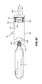
- FIG. 67 is a cross sectional view of the embodiment of FIG. 66 after the plunger has been moved to the proximal end of the device;
- FIG. 68 is a cross sectional view of another embodiment of FIG. 67 which includes an insertion tube with a repair plug for repairing a tire after injecting a sealant;
- FIG. 69 is a perspective view of for an insertion tube with an adapter, carrying a filler cord;
- FIG. 70 is a cross-sectional view of the embodiment of FIG. 69 ;
- FIG. 71 is a perspective view of the embodiment of FIG. 68 , without the inclusion of the filler cord.
- the tire repair tool 1 comprises a CO 2 cartridge (or canister) 2 , a knurled body 3 , and an insertion tube 4 .
- the gas cartridge 2 is attached to the knurled body 3
- the insertion tube 4 is attached to the knurled body.
- the knurled body 2 is the intermediate structure that controls the flow of gas from the gas cartridge and into the insertion tube.
- the insertion tube is the device by which a tire or other inflatable item receives air. In some embodiments, the insertion tube 4 is also used to repair tires or other inflatable items.
- the knurled body 3 of the tire repair tool 1 has knurling on the outside circumference of its round body.
- the knurled body can have one knurled ring 9 or at least two knurled rings 9 , 10 around the body 3 ( FIG. 8 ). While the term “knurled body” is used throughout this specification for simplicity, the term “body” or “knurled body” is more accurately be referred to as a transmittal control section 3 .
- the body 3 does not have to have knurling, and, in an alternative embodiment, the body can have a variety of other grip enhancing features, if so desired.
- the body 3 can range in size from about 1 ⁇ 2′′ to 2′′.
- the body can be larger or smaller and can be sized to comfort or need, depending on the size of the hand of the user, comfort factors, and the size of the item(s) being inflated.
- any or all of the main parts, such as the cartridge, the body, and the insertion tube 4 can be made of metal, plastic, or a combination thereof.
- the materials used in the manufacture of the knurled body 3 and the insertion tube 4 need to withstand higher pressures and lower temperatures, as compressed gases are, of course, under pressure and are usually much colder than the surrounding environs.
- the gas cartridge 2 can be of almost any length. What is important is that the cartridge 2 and the body 3 be able to mate.
- the body 3 has a mount for attachment of an air hose. All embodiments of the air body have an air passageway 12 which allows the air or CO 2 of the cartridge 2 to pass through the body 3 and out through a hose or an insertion tube 4 .
- first female threaded section 7 inside 5 of the distal end 6 of the knurled body 3 .
- This first female threaded section 7 mates with and threads with male threads 8 on the gas cartridge 2 .
- the gas cartridge 2 is thus firmly affixed to the knurled body 3 .
- threaded sections are shown in the figures, the gas cartridge 2 can be mated to the knurled body by different means, including snap fittings, locking mechanisms, etc. It should be noted that almost any gas (such as nitrogen) can be used in the gas cartridge 2 , as long as the gas does not adversely affect the item into which the gas is to be filled. The gas used should also not adversely affect the tire repair tool 1 .
- Gases including but not limited to carbon dioxide or air can be used.
- the gas cartridges 2 can also include a pressurized liquid, which in some circumstances can be used to repair a tire.
- An example of using both liquids and gases in combination would be inflating a tire through the injury using a combination of CO 2 and sealant. This is much faster than repairing a tire through the valve which requires the time consuming task of removing the “core” from the valve stem to inject the sealant, replacing the core, and then inflating the tire through the valve, risking the possibility that the valve can get clogged from the scalant, dust and dirt, etc.
- a cartridge seal 11 fitted over the proximal end of the threads of the cartridge 2 serves to seal the gas or pressurized liquid within the cartridge until needed.
- the cartridge seal 11 is usually made of steel, which is the “standard” in the industry, although some other metal coverings may be used.
- the insertion tube 4 is connected to the proximal end of the knurled body 3 .
- the insertion tube 4 has, at its distal end 27 , male threads 28 which are threaded into threads 26 within the proximal end 25 of the knurled body 3 .
- the insertion tube 4 has a collar 29 below the threads 28 which fit within the proximal opening 30 of the knurled body.
- There is an “o” ring 31 which fits tightly on top of the collar 29 and tightly around the female threads, thereby preventing or limiting air, gas, or liquid leakage.
- any form of connection can be used for attachment, as long as the insertion tube 4 does not come off when air passes through the body 3 into the insertion tube 4 .
- the insertion tube 4 is “permanently” or integrally attached to the body 3 .
- the insertion tube 4 has an upper section 33 and a lower section 34 , separated by an air impermeable wall or solid barrier 35 .
- the wall 35 can be made of any material compatible with the insertion tube 4 , but is normally made of the same material as the insertion tube 4 . As such, in one embodiment, the wall is integrally molded with the wall 35 .
- the upper section 33 has at least one hole 36 , and in another embodiment, two holes 36 , 37 through which the CO 2 gas, other gas(es), or combinations of liquids and gas flow(s) to inflate the tire ( FIG. 3 ). In yet another embodiment, there are a plurality of holes through which the gases and/or liquids can flow.
- gas or “air”
- air air
- the terms can be inclusive of gas, air, liquid, and any combination thereof.
- Air passageways referred to in this disclosure can allow for the passage of air, gas, liquid, or any combination thereof.
- lower section 34 has an opening 38 at its proximal end 39 .
- the opening 38 there can be fitted with at least one repair plug 40 (as described in U.S. Pat. No. 8,707,829, issued Apr. 29, 2014, and U.S. Pat. No. 9,067,368, issued Jun. 30, 2015, both incorporated herein by reference in their entirety.)
- the repair plug 40 comprises a pointed conical metal tip 41 ending having at its distal end a circumferential shoulder 42 and a tip collar 43 positioned proximally to the circumferential shoulder 42 .
- a rubberized impregnated cord 44 is attached to an inside of a distal end of the conical tip 41 .
- the reverse blocking valve is formed by a resilient member such as a check valve compression spring 46 , and a ball bearing seal 47 on top of the valve compression spring 46 .
- a resilient member such as a check valve compression spring 46
- a ball bearing seal 47 On top of the ball bearing seal 47 is an O-ring seal 48 for the positioning of the ball bearing seal 47 and on top of the O-ring seal 48 is a threaded ring stop 49 , which is then screwed into an inside threaded channel 50 of the insertion tube 4 has at its distal end 27 .
- This reverse blocking valve prevents the loss of tire pressure during a pressurized cartridge change, if necessary, such that the air from the higher air pressured tire is prevented from escaping by the ball bearing seal 47 pushed up against the O-ring seal, preventing air from escaping.
- the insertion tube 4 could be anywhere from 3 ⁇ 4′′ to 6′′ or more long. For example, in one embodiment, when in use with larger tires, the insertion tube 4 is longer. In another embodiment, the insertion tube 4 is 3 ⁇ 4′′ to 4′′ long, and in another embodiment, the insertion tube 4 is from about 1′′ to about 3′′ long. Sizes may vary outside of these parameters.
- the seal 11 securing the pressurized gas in the cartridge 2 must be broken . . . .
- a number of structures may be used that allows for the piercing of the gas cartridge seal 11 .
- the knurled body 3 comprises a cartridge tip piercing component 51 having a hollow pin 52 extending through the cartridge tip body 53 .
- the hollow pin 52 extends far enough such that when the gas cartridge is threaded far enough into the knurled body 4 , the hollow pin pierces the cartridge thread seal.
- the seal 11 is pierced, the CO 2 passes directly from the gas cartridge 2 through the cartridge tip piercing component 51 , and through the insertion tube 4 .
- the end of the hollow pin is at an angle to make piercing the seal easier.
- FIGS. 9 and 11-15 are directed towards another embodiment that efficiently releases and conserves the CO 2 gas in the cartridge.
- FIG. 13 illustrates a cartridge tip piercing component 203 having a continuous air groove 32 in the shoulder 204 and elongated body 205 .
- FIG. 9 shows the placement of the cartridge piercing component 203 within the tool 1 .
- the conical piercing tip 201 of the cartridge tip piercing component 203 efficiently and easily pierces the flat steel seal or flexible seal 11 covering one end of the cartridge 2 , so that pressurized gas can flow from the cartridge 2 , through the body 3 , and through the insertion tube 4 and into the tire or the item being inflated.
- the seal and/or solid rim will be positioned against the piercing tip shoulder rim 202 , which will effectively prevent air from escaping through the cartridge 2 .
- the O-rings 901 and 18 help prevent any incidental leakage from escaping from the tool or from going through the body 3 out the insertion tube.
- FIG. 11 shows the cartridge piercing component 203 in use without the groove 900 and without the O-ring 901 . This is shown in FIGS. 9, 15 a , and 15 b.
- FIGS. 15 a and 15 b illustrate the effectiveness of the cartridge piercing component in preventing undesired loss of CO 2 from the cartridge.
- FIG. 15 a shows the air passageway as the seal 11 is being pierced by the conical piercing tip 201 , just when the gas cartridge 2 is threaded clockwise, but not so far as to cut off air flow.
- the arrows in the FIG. 15 a shows the passage of air from the cartridge 2 and through the continuous air groove 32 and down through the insertion tube.
- the insertion tube 4 is entirely or almost entirely within the tire.
- the CO 2 cartridge 2 is screwed into the knurled body 3 , wherein the conical pierce tip 201 of the cartridge tip piercing component 203 pierces the cartridge seal 11 covering the threads 8 of the proximal end of the CO 2 cartridge 2 .
- the compressed gas begins to flow through the tire repair tool 1 including through the insert tube 4 , and into the tire. If more air (gas) is needed, the CO 2 cartridge 2 can be unscrewed and replaced with a fresh cartridge.
- an insertion tube cover 50 fits over the insertion tube, and in another embodiment, the distal end 51 fits up against the knurling 9 of the knurled body 3 .
- the insertion tube cover 50 is not a necessity, but it does protect the insertion tube when it is connected to the body 3 , and it can be removed when the repair tool 1 is needed. Additionally, in the event of a bicycle crash, the insertion tube cover 50 helps prevent impalement or other injury by the brass or other tip materials, when a cyclist is carrying the tool in their pocket or on their person.
- a hole 206 in the proximal end of the insertion tube cover 50 allows air to escape if, in an extremely unusual situation, a gas cartridge 2 loosens. Similarly, without hole 206 , if someone intentionally opened a valve to test it, pressure could build inside the cap, potentially creating a dangerous projectile which could cause harm or injury. The hole 206 in the insertion tube cover 50 prevents this possibility.
- the tire repair tool 1 is withdrawn. Because the shoulder of the conical tip 41 may be the same size or fractionally larger than the insertion tube 4 , the conical tip 41 with the repair plug 40 easily separates from the insertion tube 4 as the insertion tube 4 is withdrawn, allowing filling the hole in the tire by the repair plug 40 , thereby preventing air leakage. The tire is thus inflated and repaired
- FIGS. 16 and 17 are cross sections of two different insertion tubes 54 and 4 .
- Insertion tube 54 is a large insertion tube and insertion tube 4 is a normal sized insertion tube.
- the part of insertion tube 54 that connects to the body 3 is the same size as that of insertion tube 4 but the tube holding the insertion tube is wider.
- the large insertion tube 54 accommodates a large repair plug 57 and can be from about 0.15 to about 0.22 inches wide, while the plug for the “normal” sized insert tubes can range from about 0.10 to about 0.14 inches wide as measured on the inside.
- the length of the repair plug can range from about 0.7 inches to about 1.5 inches. In some embodiments, the plug can be longer such as for heavy duty bus or truck tires.
- FIGS. 18-22 represent a variety of different embodiments of the disclosure and of the attachments to the proximal end of the knurled body 3 .
- FIG. 18 is an exploded view of the tire repair tool, as described with the normal sized insertion tube 4 with a regular repair plug 40 .
- FIG. 19 is an exploded view of the tire repair tool having the larger repair plug 57 with a large insertion tube 54 , which is used for larger holes as described supra.
- FIG. 20 shows an exploded view of a repair tire tool with an inflation only insertion tube 56 .
- the inflation only tip 56 allows inflation through a cut or puncture injury in the tire.
- the tire can be repaired using the plug system described in the patents cited, supra. More specifically, in the embodiment shown in FIG. 20 , the tip of the insertion tube is blunt, not sharp.
- FIG. 21 is an exploded view of the tire repair tool having a large inflation only tip, also known as an oral inflation valve 200 .
- the tip is just an open passageway, with no impediments. This tip has the ability to fill inflatable life jackets and other pneumatic flotation devices by just inserting the tip into the flip up valve.
- FIG. 22 is an exploded view of the tire repair tool with an attachment that adapts the inflation cartridge to inflate tires having Presta/Schrader valve stem 69 (also referred to as an American/French valve stem).
- FIG. 24 is another angular view of the tire repair tool showing another embodiment allowing a different inflation tool for use for inflation of a tire through a Presta/Schrader valve stem.
- the proximal insertion tube 59 ends in a sharp slanted point to allow for the tube to push through the wound in the tire and fill the tire with air.
- a ball or globe valve 60 is positioned along passageway 12 on the inside 5 of the knurled body 3 .
- Other valve systems could be used.
- the valve is fully integrated with the body 3 , and the valve 60 is operated by the use of a ball valve lever 61 .
- the valve is located below the cartridge tip piercing component 51 and above the insertion tube 4 .
- the ball valve 60 can be positioned on the insertion tube 4 above holes 36 , 37 . Rotating the valve lever 61 90 degrees will commence or interrupt the flow of air, CO 2 , or other gases through the air passageway 12 and out through the holes 36 , 37 of insertion tube 4 .
- the tool 1 includes a pressure gauge 62 with a digital readout 63 of the tire pressure measured in pounds per square inch or in kilograms per square centimeter or bar.
- the pressure gauge 62 is positioned as integral with and part of or attached to the knurled body 3 .
- the pressure gauge 62 is positioned at the distal end of the insertion tube 4 and at the proximal end of the knurled body 3 .
- bleed valve 64 is part of the pressure gauge 62 which allows for the release of air when the air pressure of the tire is too great.
- the bleed valve 64 is not part of the pressure gauge 62 .
- the bleed valve 64 is positioned at or above the digital readout 63 , although there may be variations of its position.
- Another embodiment of the disclosure eliminated the need for having a hole 36 or holes 36 , 37 in the side of the insertion tube 4 .
- the air or CO 2 through a hole 66 in a puncture tip 67 .
- FIG. 27 there is a needle tube 67 which passes from an air passage way 35 .
- the air passageway 35 extends from the distal end to the middle of the insertion tube 4 and helps channel air or CO 2 into the needle tube 67 .
- the needle tube 67 connects with and is integral with the opening 66 through the proximal end of the needle tube 67 .
- the needle tube 67 can be connected to the air passageway 35 by a threaded connection, an O-ring at the proximal end of the passageway 35 , or any other means known in the art.
- the tool is inserted into the tire to inflate it, and can then be withdrawn, whereupon hole can be repaired by any method.
- the tire can be repaired using a Dynaplug tire repair tool or any other tire repair kit after inflation.
- pluggers 76 , 77 , 78 are integral with the insertion tube, with at least one hole 79 , 80 , 81 for the release of the CO 2 , or gases, or liquid/gas combination into the tire or other inflatable item.
- the distal end 82 , 83 , 84 , of the pluggers have a threaded section 85 , 86 , 87 that is threaded into the proximal end of the knurled body 3 , the threads being complementary to the threaded section of the body.
- a collar 88 , 89 , 90 limits the degree to which the plugger is threaded into the knurled body 3 .
- the collar 88 , 89 , 90 may serve as an O-ring or may have an O-ring positioned on top of the collar to prevent air leakage.
- the pluggers are integrally molded with or attached to the body 3 .
- the proximal end of the insertion tube is threaded, and the pluggers, threaded at their distal end, such that the pluggers are attached to the insertion tube.
- other means of attachment are available, including gluing, welding, wedging or any other means, here and throughout the description.
- FIG. 33 shows one embodiment, wherein a plugger 76 is threaded into the body with the body attached to the canister.
- a filler cord 91 is positioned or wedged between tongs 92 , 93 .
- the plugger tip 94 is pushed in through the hole in the tire up to the distal end of the plugger 76 (or insertion tube 4 ).
- the gas cartridge 2 is screwed down, and the conical piercing tip 201 or pin 52 pierces the cartridge seal 11 and inflation gas flows from the cartridge 2 , through the body 3 , through the plugger 76 and out through hole 79 and into the tire.
- the plugger is withdrawn, and the cord 91 , which is held by the tire by friction, fills the hole, limiting or preventing leakage.
- FIG. 33 shows the tool without the cord 91 .
- the tire repair tool 1 has a cartridge sleeve 95 .
- the cartridge sleeve 95 fits around and “grabs” the cartridge 2 .
- the use of the cartridge sleeve 95 negates or largely negates the need for the use of gloves, and the cartridge sleeve allows for easier manipulation of the tire repair tool 1 , and in particular, the rotation of the cartridge 2 .
- the body is made out of a high durometer or high density silicon.
- the cartridge sleeve 95 is made out of a high quality plastic, or a hard rubber.
- the cartridge sleeve could be slightly oversized (from about 3% to about 5%) to slide on the cartridge 2 easily but as soon as it is gripped with one hand, it would create an exceptional friction grip to rotate the cartridge 2 to allow for the release or closure of the flow of gas.
- a lower durometer cartridge sleeve 5 is easily stretched over the cartridge 2 .
- the cartridge sleeve 95 has a distal section 96 , a middle section 98 , and a proximal end 99 .
- the distal end has a hole 97 perpendicular through the distal section, with the hole being from 1 ⁇ 4′′ to 1′′ and large enough to put a t-handle 100 through.
- the handle t-handle 100 can be made out of wood, steel, aluminum or any other rigid material that does not easily break. The handle 100 allows the plugger to be worked into the tire, as heavier larger tires often require that more force be applied to the tool 1 to work it into the tire.
- the middle section 98 has a plurality of openings 101 , 102 , 103 which are positioned around the gas cylinder 2 . In another embodiment, there are no openings. The purpose of the openings 101 , 102 , 103 are to give the cartridge sleeve 95 enough flexibility to be fitted over the cartridge 2 .
- the proximal end 99 of the cartridge sleeve 95 has a circumference 104 that grips the gas cylinder/cartridge, such that the cartridge sleeve 95 will not slip when positioned on the cartridge 2 .
- the distal end 96 of the cartridge sleeve 95 is solid or dense 105 (with the exception of the hole 97 ).
- the distal end of the cartridge sleeve terminates in a v-rest 106 in which the distal end of the cartridge 2 resides.
- the cartridge can be rotated by firmly grasping the cartridge sleeve and rotating or turning the cartridge until the seal 17 is punctured.
- the solid section 105 of the cartridge sleeve 95 helps ensure that the rotation of the t-handle 100 will not result in undue wear and tear on the cartridge sleeve 95 .
- a regular insertion tube 4 with a repair plug 40 can be attached to the body 2 or a plugger of any sort may be used.
- a control button 107 allows for the control of passage of air from the cartridge 2 through the body 3 and out through the insertion tube 4 .
- the control button 107 is positioned through the body 3 of the repair tool 1 .
- a spring 108 inside of the button apparatus prevents gas flowing into the insertion tube such that the gas from the cylinder will not flow until the control button 107 is pressed.
- the first O-ring 109 is positioned in a cutout 111 in the button shaft 112 below the control button 107 .
- the second O-ring 110 is positioned angularly below the first O-ring 109 , positioned in a second cut out 113 in the button shaft 112 .
- the two O-rings 109 , 110 are positioned such that when the control button 107 is in the closed position, the sections of the O-rings 109 are positioned above the air passageway 12 and are positioned against a proximal wall 114 of the control button 107 within the body.
- the air or gas from the cylinder passes through the hollow pin 52 or through a double puncture wall 115 through the air passageway in the distal wall of the 116 of the control button such that CO 2 gas pressurizes the chamber 117 between the O-rings when the pin 52 punctures the cartridge.
- the walls of the extended cartridge sleeve do not terminate at the end of the cartridge 2 but have the extended cartridge sleeve 118 .
- the inside wall 121 of the extended cartridge sleeve 118 are threaded.
- the walled body 119 has extension walls 122 from its distal end, wherein the outside 123 of the walls are threaded. This allows for the threading of the cartridge sleeve 118 on to the extension walls.
- the walled body also has the button control opening 124 .
- the combination of the external canister sleeve 118 and the walled body 119 form a shell or driver housing 125 .
- a driver housing 125 needs to be adaptable to the various forms and sizes of the cartridges.
- an elongated thumb screw 126 is positioned through a hole 127 in a cap 12 at the distal end of the driver housing 125 .
- the hole 127 is threaded. As the elongated thumb screw 126 is turned, the cartridge is pushed down towards the body 3 and towards the pin insert which will puncture the seal 11 on the cartridge 2 . Because of the length within the driver housing 125 , different sized cartridges of CO 2 with different amounts of CO 2 can be inserted within said driver housing 125 .
- the thumbscrew 126 or equivalent embodiment is used both to secure the cartridge 2 in place and to drive the cartridge 2 forward, towards the pin insert.
- the molded cap 128 is concavely contoured to fit the distal end 130 of the canister 2 .
- the molded cap 128 can be made out of plastic, nylon, metal, wood, or just about any other material.
- At the proximal end of the thumbscrew is a round projection 132 that fits within the cutout 131 . This gives the molded cap 128 a degree of freedom of movement, which helps accommodate some differences in the size and shape of the distal end of a cartridge 2 .
- FIGS. 45-58 show a device that allows for the tire repair tool 1 , and more specifically the insertion tube 4 with a spiral self-boring tip to be power driven into the tire.
- this embodiment of the tire repair kit 133 has a driver housing 137 with a cutaway section 135 wide and long enough into which a cartridge 2 can be fitted.
- a shank mount 138 to which a power drill can be attached.
- a hollowed out groove 139 , 140 on each side of the driver housing through which pivot arms 141 , 142 extend from each side of the distal end of the body 142 .
- a ringlet 143 , 144 , rivet, or any other appropriate structure prevents the pivot arms 141 , 142 from slipping out of the hollowed out groove 139 , 140 .
- Notches 145 , 146 in the body 149 allow for the body to swing and mate with the extended arms 147 , 148 of driver housing 137 .
- the body 142 is swung into an “open position.”
- a cartridge 2 is fitted into the threads 152 of the body 149 , and the seal (not shown) of the cartridge 2 is pierced by cartridge tip piercing component 203 .
- the cartridge is completely rotated until air passage is blocked.
- a wide insertion tube 54 is positioned at the proximal end of the body 142 .
- At the proximal end of the insertion tube 54 there is a large repair plug 57 connected to a larger spiral conical metal tip 154 .
- the repair plug 57 connected to the spiral conical metal tip 154 may be inserted into the insertion tube 54 and the insertion tube 54 is screwed into the proximal end of the body 149 .
- the cartridge 2 is swung into position within the body, and the body 149 is then pushed back into the driver housing 134 such that notches 145 , 146 in the body 142 allow for the body to and mate with the extended arms 147 , 148 of driver housing 137 , further securing the body 142 and driver housing 134 together.
- the shank mount 138 is attached to the power drill.
- the power drill is turned on, and the insertion tube 54 is then drilled into the tire.
- the driver housing 137 is rotated out of position, and the cartridge 2 is turned counterclockwise slightly to allow air, gases, or liquid/gas combinations from the cartridge 2 to travel through the body 149 and out the insertion tube 54 through hole 207 and into the tire as shown in the figures.
- the power drill with the insertion tube 54 is withdrawn from the tire, leaving behind the spiral conical metal tip 154 on the inside of the tire, and the repair plug 57 filling in the hole in the tire, preventing further leakage.
- a cartridge less tire repair tool 208 has a hollow air collection shell 209 having a stem 210 .
- the stem may be connected to a hose supplying air to the tire or inflatable.
- the hollow air collection shell 209 is threadably connected to a body 211 by means of threads 212 on the collection shell 209 complementary to the threads 213 on the body 211 .
- the body 211 , shell 209 , and stem 210 are integrally connected, and can be one piece.
- the body 211 has no need for an insert pin or any similar structure. It has a flow through air passageway 214 and a control button switch 107 described supra, to control the filling of the tire.
- the particular stem has a Schrader valve section which is utilized to attach a portable repair inflator/compressor source to inflate tires through the injury.
- the device has an insertion tube 54 with repair plug 57 .
- the device 208 is connected to a portable compressor 215 , which is in turn connected to a car charger by means of a charger adapter 216 . It should be noted that this is not a limiting feature as the device 208 could be attached to any pump, as well as to any power source.
- the tool housing is hollow and has the same male threads as other tools having a cartridge 2 as described above.
- the body and the insertion tube with a cartridge if desired, if the body 3 has a cartridge piercing tip.
- the cartridge less repair tool 208 can operate on DC or AC power compressor hooks up its air line via a quick connect or other connector means to inflate the tire with any type of gas, normally air or nitrogen gas.
- any type of gas normally air or nitrogen gas.
- virtually any non-combustible gas can be used.
- the tool housing is hollow and has the same male threads as a threaded CO 2 so the embodiment shown above with the push button valve and threaded insertion tube is that same embodiment that can be used with threaded insertion tubes.
- a cartridge tip piercing component 203 is fitted within the body 211 . Any practical adapter to deliver air from a compressor to the body can be used.
- the body 3 of the repair tool 217 is attached to another empty housing 218 .
- the threaded nut 220 is then moved towards the distal end of the coupler 219 .
- the hose is or other flexible cable is slipped through the nut 220 , over the distal end of the coupler 219 and up to the proximal end of the coupler 219 .
- the threaded nut is tightened to the threaded collar 221 of the coupler 219 , with the hose or cable between the threaded collar 221 and the threaded nut 220 .
- the coupler 219 and housing 218 is threaded into a Schraeder male valve stem connector body 222 , which is connected to an insertion tube 54 and a repair plug 57 .
- a Schraeder male valve stem connector body 222 which is connected to an insertion tube 54 and a repair plug 57 .
- any body 3 that can be fitted with a “large” insertion tube 57 can also be fitted with a regular insertion tube 4 as the size of the threaded mount is the same.
- the empty housing (or air chamber) 218 is threaded onto the body 218 just as a gas cartridge 2 would.
- the coupler is threaded 222 , over which an air hose or a Schrader valve can be threaded.
- 223 of the coupler is threaded, and an air hose with a male thread can be attached to the coupler.
- the air hose itself can be used of any appropriate material including but not limited to rubber, plastic, nylon, polyurethane, braided stainless steel, other plastic hose materials and any combination thereof.
- FIG. 1 Another embodiment attaches a coiled air hose 224 connected to the body 3 by means of an adapter 225 .
- a cartridge 2 is attached to distal end of the body 3 .
- a first threaded arm 226 connected to the first side of the adapter 225 is threaded into the proximal end 402 of the body 3 (Note that in all of the embodiments where there are threads there can be the reverse of which thread is threaded into the other thread).
- the second threaded arm 227 of the adapter is connected to a coiled hose 228 or other type of hose.
- the proximal end 229 of the coiled hose 229 is attached to a Schrader or Presta valve stem 230 . Other valve stems could be used in other embodiments.
- the adapter 225 also has a female threaded port 231 large enough to accept a threaded pressure gauge 232 .
- the distal end of the hose has a threaded connection 401 which is threaded over the second threaded arm.
- a CO 2 cartridge 2 is attached to a sealant dispenser 233 for filling and sealing tires.
- the sealant dispenser 233 has at its distal end female threads 234 to which the cartridge 2 is attached. It has a top wall 235 , a bottom wall 236 , and a distal wall 237 containing the female threads or other attachment devices, and a tip piercing component 238 .
- a dispenser needle 239 attached to an end cap 240 that is removable so that the tire sealant can be poured in.
- a movable plunger, 241 which comprises at least one O-ring 242 , and in another embodiment a second O-ring 243 for stability and to prevent sealant leakage.
- a pressure relief valve 245 allows CO 2 gas escape after the plunger pushes the sealant into the tire. It should be noted that other methods of attaching the cartridge to the dispenser may be used, such as locking snap rings.
- the insertion tube 4 has the upper section 33 comprising at least one hole 36 through which air and sealant passes, and the lower section 34 has an opening through which a repair plug 40 fits.
- the upper and lower sections are separated by wall 35 .
- There is also a valve tube 246 which, when the pressure relief valve is pressed, air travels from the release valve 247 , through the valve tube 246 and into the upper section of the insertion tube and out through the at least one hole 36 .
- the sealant dispenser 233 is filled with the sealant, and the removable end cap 240 is fitted back on the proximal end of the sealant dispenser 233 .
- the CO 2 cartridge is attached, the CO 2 seal is punctured and the plunger 241 moves forward, dispensing the sealant through the dispenser needle 239 or through the insertion tube 4 and out through the at least one hole 36 .
- the release of the sealant should be at a reasonably fast but controlled rate of speed.
- elements may be added to this device. Indeed, all elements in the description, can, where practical, be used with other elements of the disclosure.
- the O-ring plunger is near the proximal end of the chamber after the sealant has been injected into the tire.
- the release valve 247 When an insertion tube 4 is used the release valve 247 is pressed and air travels through the valve tube 246 which allows both the hole 36 to be blown clean and allows the tire to be filled to the desired pressure. The release valve 247 is closed by removing one's finger from the valve 239 . The insertion tube is then withdrawn, leaving behind the plug 40 to complete the seal and repair of the tire.
- the flow switch button 107 a pressure gauge 62 with a digital readout 63 , reverse blocking valve formed by a check valve compression spring 46 , the ball valve lever 61 and the other features mentioned, supra, can be used alone or in combination with the other features in all of the embodiments, in this disclosure.
- a bullet nosed cylindrical insertion tube 400 has a distal cylindrical section 401 and a bullet nosed proximal section 402 .
- the proximal section has an air hole or passageway 403 .
- the bullet nosed cylindrical insertion tube 400 is bored out up to the air hole 403 .
- a continuous indenture or groove 405 into which is fitted a repair cord 410 wraps around from one side of the distal section 401 , up and around the proximal end 406 , and continues down the other side 408 in a mirror image.
- the distal end of the insertion tube is threaded into the proximal end of the body 3 of the tire repair kit.
- a repair cord can be added in the insertion tube indentures which can then be inserted into the tire.
- this insertion tube can have a variety of geometric shapes, and does not have to be cylindrical.
Landscapes
- Engineering & Computer Science (AREA)
- Mechanical Engineering (AREA)
Abstract
Description
Claims (18)
Priority Applications (4)
| Application Number | Priority Date | Filing Date | Title |
|---|---|---|---|
| US15/732,489 US10399397B2 (en) | 2016-11-21 | 2017-11-20 | Device and method for inflating and repairing tires and other inflatables |
| US16/602,196 US10940725B2 (en) | 2016-11-21 | 2019-08-28 | Device and method for inflating and repairing tires and other inflatables |
| US16/602,197 US10821789B2 (en) | 2016-11-21 | 2019-08-28 | Device and method for inflating and repairing tires and other inflatables |
| US16/602,680 US10913317B2 (en) | 2016-11-21 | 2019-11-20 | Device and method for inflating and repairing tires and other inflatables |
Applications Claiming Priority (4)
| Application Number | Priority Date | Filing Date | Title |
|---|---|---|---|
| US201662424966P | 2016-11-21 | 2016-11-21 | |
| US201762602260P | 2017-04-19 | 2017-04-19 | |
| US201762602611P | 2017-05-01 | 2017-05-01 | |
| US15/732,489 US10399397B2 (en) | 2016-11-21 | 2017-11-20 | Device and method for inflating and repairing tires and other inflatables |
Related Child Applications (2)
| Application Number | Title | Priority Date | Filing Date |
|---|---|---|---|
| US16/602,197 Division US10821789B2 (en) | 2016-11-21 | 2019-08-28 | Device and method for inflating and repairing tires and other inflatables |
| US16/602,196 Continuation US10940725B2 (en) | 2016-11-21 | 2019-08-28 | Device and method for inflating and repairing tires and other inflatables |
Publications (2)
| Publication Number | Publication Date |
|---|---|
| US20180141396A1 US20180141396A1 (en) | 2018-05-24 |
| US10399397B2 true US10399397B2 (en) | 2019-09-03 |
Family
ID=62144665
Family Applications (4)
| Application Number | Title | Priority Date | Filing Date |
|---|---|---|---|
| US15/732,489 Active - Reinstated US10399397B2 (en) | 2016-11-21 | 2017-11-20 | Device and method for inflating and repairing tires and other inflatables |
| US16/602,197 Active US10821789B2 (en) | 2016-11-21 | 2019-08-28 | Device and method for inflating and repairing tires and other inflatables |
| US16/602,196 Active US10940725B2 (en) | 2016-11-21 | 2019-08-28 | Device and method for inflating and repairing tires and other inflatables |
| US16/602,680 Active US10913317B2 (en) | 2016-11-21 | 2019-11-20 | Device and method for inflating and repairing tires and other inflatables |
Family Applications After (3)
| Application Number | Title | Priority Date | Filing Date |
|---|---|---|---|
| US16/602,197 Active US10821789B2 (en) | 2016-11-21 | 2019-08-28 | Device and method for inflating and repairing tires and other inflatables |
| US16/602,196 Active US10940725B2 (en) | 2016-11-21 | 2019-08-28 | Device and method for inflating and repairing tires and other inflatables |
| US16/602,680 Active US10913317B2 (en) | 2016-11-21 | 2019-11-20 | Device and method for inflating and repairing tires and other inflatables |
Country Status (1)
| Country | Link |
|---|---|
| US (4) | US10399397B2 (en) |
Cited By (4)
| Publication number | Priority date | Publication date | Assignee | Title |
|---|---|---|---|---|
| EP4019236A1 (en) * | 2020-12-15 | 2022-06-29 | Rexpair Industry Ltd | Tire repair kit system and method |
| US11673438B2 (en) | 2019-12-04 | 2023-06-13 | Louis Chuang | Bicycle tire repair device |
| EP4296045A1 (en) * | 2022-06-23 | 2023-12-27 | Illinois Tool Works Inc. | Tire repair tool |
| US12385197B1 (en) * | 2016-03-16 | 2025-08-12 | Jesse Clement Bunch | Tire deflation device |
Families Citing this family (10)
| Publication number | Priority date | Publication date | Assignee | Title |
|---|---|---|---|---|
| US10399397B2 (en) | 2016-11-21 | 2019-09-03 | United States Thermoelectric Consortium | Device and method for inflating and repairing tires and other inflatables |
| US20180257205A1 (en) * | 2017-03-09 | 2018-09-13 | Thomas Wood | Multipurpose tire tool |
| US20190100062A1 (en) * | 2017-09-29 | 2019-04-04 | Mould Flying Industrial Co., Ltd. | Screw-in valve connector |
| FR3092790B1 (en) * | 2019-02-14 | 2022-04-01 | Renault Sas | Self-repairing tire inflator tip |
| DE202019104721U1 (en) * | 2019-08-28 | 2020-12-01 | Canyon Bicycles Gmbh | Bicycle tool |
| TWI721650B (en) * | 2019-11-19 | 2021-03-11 | 極點股份有限公司 | Bicycle tire repair tool |
| GB2608629A (en) * | 2021-07-08 | 2023-01-11 | Hurst Poynton George | Tubeless tyre tool |
| US12528172B2 (en) * | 2021-12-15 | 2026-01-20 | Bib Creative Co., Ltd. | Cartridge tool set |
| US20230219384A1 (en) * | 2022-01-10 | 2023-07-13 | The Bike Hangar Llc | Tire Lever Adapter |
| TWI846361B (en) * | 2023-03-02 | 2024-06-21 | 優聚力企業股份有限公司 | Tire joint |
Citations (8)
| Publication number | Priority date | Publication date | Assignee | Title |
|---|---|---|---|---|
| US2812783A (en) * | 1954-10-28 | 1957-11-12 | Quentin C Bufogle | Device for injecting chemicals into vehicle tires and the like |
| US2925103A (en) * | 1956-11-23 | 1960-02-16 | Kerr Chemicals Inc | Valve assembly |
| US3834433A (en) * | 1971-11-22 | 1974-09-10 | A Thompson | Cartridge-actuated device for inflating tires and the like |
| US5012954A (en) * | 1990-02-08 | 1991-05-07 | Will Conrad A | Tire inflation system |
| US20110284124A1 (en) * | 2010-05-20 | 2011-11-24 | Ying-Che Huang | High-Pressure Inflation Pump |
| US8707829B2 (en) | 2012-05-23 | 2014-04-29 | United States Thermoelectric Consortium | Tire repair kit |
| US9067368B2 (en) | 2012-05-23 | 2015-06-30 | United States Thermoelectric Consortium (USTC) | Tire repair kit |
| US20150258970A1 (en) * | 2014-03-12 | 2015-09-17 | Tuo-Jen Chen | Tire inflator |
Family Cites Families (7)
| Publication number | Priority date | Publication date | Assignee | Title |
|---|---|---|---|---|
| FR2390302A1 (en) * | 1977-05-13 | 1978-12-08 | Wolber | PROCESS AND DEVICE FOR REPAIRING HOSES WITHOUT A CHAMBER |
| US4934543A (en) * | 1988-02-22 | 1990-06-19 | Schmidt Andrew C | Bottle cap and dispenser |
| US5590696A (en) * | 1994-07-14 | 1997-01-07 | Reebok International Ltd. | Inflation system utilizing a pressurized gas inflation device and adaptor therefor |
| TW456491U (en) * | 2000-12-28 | 2001-09-21 | Wu Shu Mu | Safety switch for air pump with high-pressure steel cylinder |
| TW530884U (en) * | 2002-06-03 | 2003-05-01 | Luo-Ping Wang | Air pump allowing pumping by air cylinder or manually |
| US10399397B2 (en) | 2016-11-21 | 2019-09-03 | United States Thermoelectric Consortium | Device and method for inflating and repairing tires and other inflatables |
| US10611103B2 (en) * | 2017-09-12 | 2020-04-07 | Bell Sports, Inc. | Tire repair tool and method of repairing a tire puncture with tire plugs |
-
2017
- 2017-11-20 US US15/732,489 patent/US10399397B2/en active Active - Reinstated
-
2019
- 2019-08-28 US US16/602,197 patent/US10821789B2/en active Active
- 2019-08-28 US US16/602,196 patent/US10940725B2/en active Active
- 2019-11-20 US US16/602,680 patent/US10913317B2/en active Active
Patent Citations (8)
| Publication number | Priority date | Publication date | Assignee | Title |
|---|---|---|---|---|
| US2812783A (en) * | 1954-10-28 | 1957-11-12 | Quentin C Bufogle | Device for injecting chemicals into vehicle tires and the like |
| US2925103A (en) * | 1956-11-23 | 1960-02-16 | Kerr Chemicals Inc | Valve assembly |
| US3834433A (en) * | 1971-11-22 | 1974-09-10 | A Thompson | Cartridge-actuated device for inflating tires and the like |
| US5012954A (en) * | 1990-02-08 | 1991-05-07 | Will Conrad A | Tire inflation system |
| US20110284124A1 (en) * | 2010-05-20 | 2011-11-24 | Ying-Che Huang | High-Pressure Inflation Pump |
| US8707829B2 (en) | 2012-05-23 | 2014-04-29 | United States Thermoelectric Consortium | Tire repair kit |
| US9067368B2 (en) | 2012-05-23 | 2015-06-30 | United States Thermoelectric Consortium (USTC) | Tire repair kit |
| US20150258970A1 (en) * | 2014-03-12 | 2015-09-17 | Tuo-Jen Chen | Tire inflator |
Cited By (4)
| Publication number | Priority date | Publication date | Assignee | Title |
|---|---|---|---|---|
| US12385197B1 (en) * | 2016-03-16 | 2025-08-12 | Jesse Clement Bunch | Tire deflation device |
| US11673438B2 (en) | 2019-12-04 | 2023-06-13 | Louis Chuang | Bicycle tire repair device |
| EP4019236A1 (en) * | 2020-12-15 | 2022-06-29 | Rexpair Industry Ltd | Tire repair kit system and method |
| EP4296045A1 (en) * | 2022-06-23 | 2023-12-27 | Illinois Tool Works Inc. | Tire repair tool |
Also Published As
| Publication number | Publication date |
|---|---|
| US10913317B2 (en) | 2021-02-09 |
| US20200223267A9 (en) | 2020-07-16 |
| US10821789B2 (en) | 2020-11-03 |
| US20200198417A1 (en) | 2020-06-25 |
| US10940725B2 (en) | 2021-03-09 |
| US20190389259A1 (en) | 2019-12-26 |
| US20200062054A1 (en) | 2020-02-27 |
| US20180141396A1 (en) | 2018-05-24 |
Similar Documents
| Publication | Publication Date | Title |
|---|---|---|
| US10940725B2 (en) | Device and method for inflating and repairing tires and other inflatables | |
| US4489855A (en) | Instant tire inflator | |
| US7866335B2 (en) | Air valve connecting device for connecting different valves | |
| US11904644B2 (en) | Inflation system for tubeless tires | |
| US9989179B2 (en) | Attachment for different air valve | |
| US5665908A (en) | Manual tire deflating and pressure indicating device | |
| MXPA06002652A (en) | Inflation valve with pneumatic assist. | |
| US12454158B2 (en) | Pneumatic chuck including valve core interface | |
| CN210970571U (en) | Pneumatic tire seater for seating tires on wheels | |
| US5803108A (en) | Tool and method for inserting a filter element into the valve stem of a wheel assembly | |
| US9346331B2 (en) | Bead seater supply line accessory | |
| US9387738B2 (en) | Attachment for air valve | |
| US20150240981A1 (en) | Combination Tire Valve Core Removal and Fluid Fill Tool | |
| US10280912B2 (en) | Air valve connecting device for different inflation valves | |
| TWI783435B (en) | Tool for repairing and inflating tires | |
| US2920638A (en) | Valved container cap having a frangible disk therein | |
| US10208865B2 (en) | Air valve connecting device | |
| US7137403B2 (en) | Device for producing bypasses under pressure in fluid piping systems | |
| US3052141A (en) | Tire repair gun and cartridge | |
| US10759238B2 (en) | Manual internal slip valve pneumatic tire seater | |
| US20140048215A1 (en) | High volume air valve for a tire bead tool | |
| US1902919A (en) | Coupling | |
| US736025A (en) | Detachable valve and implement for attaching same. | |
| US11267299B1 (en) | Hand-held device for sealing a tire to a rim during tire changing | |
| WO2011106271A2 (en) | Apparatus and method for repairing a tire |
Legal Events
| Date | Code | Title | Description |
|---|---|---|---|
| FEPP | Fee payment procedure |
Free format text: ENTITY STATUS SET TO SMALL (ORIGINAL EVENT CODE: SMAL); ENTITY STATUS OF PATENT OWNER: SMALL ENTITY |
|
| STPP | Information on status: patent application and granting procedure in general |
Free format text: NOTICE OF ALLOWANCE MAILED -- APPLICATION RECEIVED IN OFFICE OF PUBLICATIONS |
|
| STPP | Information on status: patent application and granting procedure in general |
Free format text: AWAITING TC RESP, ISSUE FEE PAYMENT VERIFIED |
|
| STPP | Information on status: patent application and granting procedure in general |
Free format text: PUBLICATIONS -- ISSUE FEE PAYMENT VERIFIED |
|
| STCF | Information on status: patent grant |
Free format text: PATENTED CASE |
|
| FEPP | Fee payment procedure |
Free format text: MAINTENANCE FEE REMINDER MAILED (ORIGINAL EVENT CODE: REM.); ENTITY STATUS OF PATENT OWNER: SMALL ENTITY |
|
| LAPS | Lapse for failure to pay maintenance fees |
Free format text: PATENT EXPIRED FOR FAILURE TO PAY MAINTENANCE FEES (ORIGINAL EVENT CODE: EXP.); ENTITY STATUS OF PATENT OWNER: SMALL ENTITY |
|
| STCH | Information on status: patent discontinuation |
Free format text: PATENT EXPIRED DUE TO NONPAYMENT OF MAINTENANCE FEES UNDER 37 CFR 1.362 |
|
| FP | Lapsed due to failure to pay maintenance fee |
Effective date: 20230903 |
|
| FEPP | Fee payment procedure |
Free format text: SURCHARGE, PETITION TO ACCEPT PYMT AFTER EXP, UNINTENTIONAL. (ORIGINAL EVENT CODE: M2558); ENTITY STATUS OF PATENT OWNER: SMALL ENTITY Free format text: PETITION RELATED TO MAINTENANCE FEES FILED (ORIGINAL EVENT CODE: PMFP); ENTITY STATUS OF PATENT OWNER: SMALL ENTITY |
|
| MAFP | Maintenance fee payment |
Free format text: PAYMENT OF MAINTENANCE FEE, 4TH YR, SMALL ENTITY (ORIGINAL EVENT CODE: M2551); ENTITY STATUS OF PATENT OWNER: SMALL ENTITY Year of fee payment: 4 |
|
| PRDP | Patent reinstated due to the acceptance of a late maintenance fee |
Effective date: 20240214 |
|
| FEPP | Fee payment procedure |
Free format text: PETITION RELATED TO MAINTENANCE FEES GRANTED (ORIGINAL EVENT CODE: PMFG); ENTITY STATUS OF PATENT OWNER: SMALL ENTITY |
|
| STCF | Information on status: patent grant |
Free format text: PATENTED CASE |