US1038917A - Buggy or wagon greaser. - Google Patents
Buggy or wagon greaser. Download PDFInfo
- Publication number
- US1038917A US1038917A US65654411A US1911656544A US1038917A US 1038917 A US1038917 A US 1038917A US 65654411 A US65654411 A US 65654411A US 1911656544 A US1911656544 A US 1911656544A US 1038917 A US1038917 A US 1038917A
- Authority
- US
- United States
- Prior art keywords
- slots
- bolt
- slot
- head
- lever
- Prior art date
- Legal status (The legal status is an assumption and is not a legal conclusion. Google has not performed a legal analysis and makes no representation as to the accuracy of the status listed.)
- Expired - Lifetime
Links
- 230000001869 rapid Effects 0.000 description 1
Images
Classifications
-
- B—PERFORMING OPERATIONS; TRANSPORTING
- B66—HOISTING; LIFTING; HAULING
- B66F—HOISTING, LIFTING, HAULING OR PUSHING, NOT OTHERWISE PROVIDED FOR, e.g. DEVICES WHICH APPLY A LIFTING OR PUSHING FORCE DIRECTLY TO THE SURFACE OF A LOAD
- B66F15/00—Crowbars or levers
Definitions
- My invention is an improvement in wagon greasers, and has for its object the provision of a simple, inexpensive, easily operated device of the character specified, consisting of but few parts, capable of being stored in compact form, and wherein a variety of adjustments are possible.
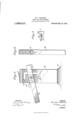
- Figure l is a side view of the improvement
- Fig. 2 is a side view of the lever
- Fig. 3 is a plan View of the bolt.
- the present embodiment of the invention comprises a standard or upright A, and a lever B, for cooperating therewith.
- the upright or standard A is of suitable length or height and width and thickness and may be of any suitable material.
- the lower end thereof is enlarged to provide a foot or base a, to provide for greater steadiness when in use.
- the upright is provided with a plurality of transverse slots a, a and a the slots a and a being parallel and spaced apart from each other, while the latter slot a is at right angles to the others, and intersects both at one end.
- the slot at is of greater length than the slot at a", so that the slots together form an opening corresponding to the shape of the letter F, reversed of course on one face of the upright.
- the lever B is preferably square in cross section, and is of suitable length and size.
- an opening I Near one end of the lever an opening I; is provided, the said opening being square in cross section, and designed to receive a pivot pin or bolt C.
- the opening I) is spaced apart from the adjacent end of the lever a suflicient distance to permit the said end to engage beneath the axle of the vehicle with which the device is to be used.
- the bolt C is provided with a head a of a width to permit the passage of the head through the slots 0, a or a and of greater length than the width of the slots, to prevent withdrawal of the bolt, when the head is turned transversely of the slot. That portion 0 of the bolt adjacent to the head is round, that is circular in cross section, while the portion 0 remote from the head is square in cross section to fit the opening 6 of the lever.
- the bolt C is passed through the opening I) of the lever, and through slot a of the upright or standard, and the device is ready for use. In lifting the rear axle, the bolt C is left in this position, but when in use at the front axle, the bolt is moved to slot (1 passing along slot a
- the portion 0 of the bolt is rounded to permit the easy turning of the bolt, but it is obvious that the said portion may be square if desired.
- the lever may be de tached from the upright, by turning the head of the bolt in alinement with either of the slots.
- the device may also be used at the bottom of slot a if desired. It will be evident that three adjustments are thus permitted, and the number of adjustments might be increased, by extending slot a and running off other slots horizontally.
- the axle or other element being lifted may be lifted onto the upper end of the upright.
- the said upper end is preferably rounded or beveled downwardly in both directions, as
- the lever may be detached from the standard, when the device is not in use, by merely turning the bolt head into alinement with any of the slots, and withdrawing the bolt.
- a device of the character specified comprising an upright or standard having a base, and having its upper end beveled in opposite directions and having near its upper end a plurality of spaced parallel substantially horizontal slots, and a vertical slot connecting the horizontal slots at one end and extending below the lowermost of the said slots, said slots being of equal width, a lever provided near one end with an opening polygonal in cross section, and a pivot bolt having one end polygonal in cross section to fit the lever opening and the other end circular in cross section for engaging the slots of the standard, said bolt having a head of a width to enter the slots, and of a length to extend transversely on each side of a slot.
- a standard having near its upper end a vertical transverse slot, and a plurality of horizontal slots leading laterally from the vertical slot and spaced apart from each other, and a lever provided near one end With a laterally extending bolt for engaging the slots, said bolt having a head of greater length than the Width of the slots and of a Width less than that of the slots to permit the head to pass through the said slots, the bolt being cylindrically adjacent to the head, and polygonal in cross section Within the lever, said lever having an opening for the bolt fitting the polygonal portion thereof.
- a device of the character specified comprising a standard having near its upg per end a vertical transverse slot, and a plurality' of horizontal slots leading laterally from the vertical slot and spaced apart from each other, and a lever provided near one end 'With a laterally extending bolt for en'- gaging the slots, said bolt having a head of greater length than the Width of the slots and of a Width less than that of the slots to permit the head to pass through the said slots, the bolt being cylindrically adjacent to the head.
- a device of the character specified comprising a standard having near its up per end a vertical transverse slot, and a plurality of horizontal slots leading laterally from the vertical slot and spaced apart from each other, and a lever provided near one end with a laterally extending bolt for engaging the slots, said bolt having a head of greater length than the Width of the slots and of a Width less than that of the slots to permit the head to pass through the said SlOtS. WILLIAM T. MADDOX.
Landscapes
- Life Sciences & Earth Sciences (AREA)
- Engineering & Computer Science (AREA)
- Geology (AREA)
- Mechanical Engineering (AREA)
- Structural Engineering (AREA)
- Body Structure For Vehicles (AREA)
Description
Nrrn
WILLIAM T. MADDOX, OF ALEXANDRIA, LOUISIANA.
BUGGY OR WAGON GREASER.
Specification of Letters Patent.
Patented Sept. 17,1912.
Application filed October 24, 1911. Serial No. 656,544.
T 0 all whom it may concern:
Be it known that I, lVILLIAM T. MADDOX, a citizen of the United States, and a resident of Alexandria, in the parish of Rapides and State of Louisiana, have invented a new and Improved Buggy or \Vagon Greaser, of which the following is a full, clear, and exact description.
My invention is an improvement in wagon greasers, and has for its object the provision of a simple, inexpensive, easily operated device of the character specified, consisting of but few parts, capable of being stored in compact form, and wherein a variety of adjustments are possible.
In the drawings, Figure l is a side view of the improvement; Fig. 2 is a side view of the lever; and Fig. 3 is a plan View of the bolt.
The present embodiment of the invention comprises a standard or upright A, and a lever B, for cooperating therewith. The upright or standard A is of suitable length or height and width and thickness and may be of any suitable material.
Preferably, the lower end thereof is enlarged to provide a foot or base a, to provide for greater steadiness when in use. The upright is provided with a plurality of transverse slots a, a and a the slots a and a being parallel and spaced apart from each other, while the latter slot a is at right angles to the others, and intersects both at one end. v
The slot at is of greater length than the slot at a", so that the slots together form an opening corresponding to the shape of the letter F, reversed of course on one face of the upright. The lever B is preferably square in cross section, and is of suitable length and size.
Near one end of the lever an opening I; is provided, the said opening being square in cross section, and designed to receive a pivot pin or bolt C. The opening I) is spaced apart from the adjacent end of the lever a suflicient distance to permit the said end to engage beneath the axle of the vehicle with which the device is to be used.
The bolt C is provided with a head a of a width to permit the passage of the head through the slots 0, a or a and of greater length than the width of the slots, to prevent withdrawal of the bolt, when the head is turned transversely of the slot. That portion 0 of the bolt adjacent to the head is round, that is circular in cross section, while the portion 0 remote from the head is square in cross section to fit the opening 6 of the lever.
The bolt C is passed through the opening I) of the lever, and through slot a of the upright or standard, and the device is ready for use. In lifting the rear axle, the bolt C is left in this position, but when in use at the front axle, the bolt is moved to slot (1 passing along slot a The portion 0 of the bolt is rounded to permit the easy turning of the bolt, but it is obvious that the said portion may be square if desired. The lever may be de tached from the upright, by turning the head of the bolt in alinement with either of the slots.
The device may also be used at the bottom of slot a if desired. It will be evident that three adjustments are thus permitted, and the number of adjustments might be increased, by extending slot a and running off other slots horizontally.
When the bolt is in slot at, the axle or other element being lifted may be lifted onto the upper end of the upright. The said upper end is preferably rounded or beveled downwardly in both directions, as
indicated at a in order that the weight may be easily shifted to either side.
The lever may be detached from the standard, when the device is not in use, by merely turning the bolt head into alinement with any of the slots, and withdrawing the bolt.
I claim 1. A device of the character specified, comprising an upright or standard having a base, and having its upper end beveled in opposite directions and having near its upper end a plurality of spaced parallel substantially horizontal slots, and a vertical slot connecting the horizontal slots at one end and extending below the lowermost of the said slots, said slots being of equal width, a lever provided near one end with an opening polygonal in cross section, and a pivot bolt having one end polygonal in cross section to fit the lever opening and the other end circular in cross section for engaging the slots of the standard, said bolt having a head of a width to enter the slots, and of a length to extend transversely on each side of a slot.
2. A device of the character specified,
comprising a standard having near its upper end a vertical transverse slot, and a plurality of horizontal slots leading laterally from the vertical slot and spaced apart from each other, and a lever provided near one end With a laterally extending bolt for engaging the slots, said bolt having a head of greater length than the Width of the slots and of a Width less than that of the slots to permit the head to pass through the said slots, the bolt being cylindrically adjacent to the head, and polygonal in cross section Within the lever, said lever having an opening for the bolt fitting the polygonal portion thereof.
3. A device of the character specified, comprising a standard having near its upg per end a vertical transverse slot, and a plurality' of horizontal slots leading laterally from the vertical slot and spaced apart from each other, and a lever provided near one end 'With a laterally extending bolt for en'- gaging the slots, said bolt having a head of greater length than the Width of the slots and of a Width less than that of the slots to permit the head to pass through the said slots, the bolt being cylindrically adjacent to the head.
4. A device of the character specified, comprising a standard having near its up per end a vertical transverse slot, and a plurality of horizontal slots leading laterally from the vertical slot and spaced apart from each other, and a lever provided near one end with a laterally extending bolt for engaging the slots, said bolt having a head of greater length than the Width of the slots and of a Width less than that of the slots to permit the head to pass through the said SlOtS. WILLIAM T. MADDOX.
Witnesses WM. L. BAILLIo, HENRY BOYLE.
Copies of this patent may be obtained for five cents each, by addressing the Commissioner of Patents,
Washington, I). C.
Priority Applications (1)
| Application Number | Priority Date | Filing Date | Title |
|---|---|---|---|
| US65654411A US1038917A (en) | 1911-10-24 | 1911-10-24 | Buggy or wagon greaser. |
Applications Claiming Priority (1)
| Application Number | Priority Date | Filing Date | Title |
|---|---|---|---|
| US65654411A US1038917A (en) | 1911-10-24 | 1911-10-24 | Buggy or wagon greaser. |
Publications (1)
| Publication Number | Publication Date |
|---|---|
| US1038917A true US1038917A (en) | 1912-09-17 |
Family
ID=3107194
Family Applications (1)
| Application Number | Title | Priority Date | Filing Date |
|---|---|---|---|
| US65654411A Expired - Lifetime US1038917A (en) | 1911-10-24 | 1911-10-24 | Buggy or wagon greaser. |
Country Status (1)
| Country | Link |
|---|---|
| US (1) | US1038917A (en) |
-
1911
- 1911-10-24 US US65654411A patent/US1038917A/en not_active Expired - Lifetime
Similar Documents
| Publication | Publication Date | Title |
|---|---|---|
| US1266929A (en) | Table and desk. | |
| US661691A (en) | Baggage-check carrier. | |
| US320487A (en) | William a | |
| US14680A (en) | Vault-cover | |
| US1020349A (en) | Dirt-receptacle. | |
| US752115A (en) | Post-hole digger | |
| US640687A (en) | Blackboard-support. | |
| US83947A (en) | Improved lifting-jack and cant-hook | |
| US11506A (en) | Fukhtttjue-castek | |
| US1031414A (en) | Plow. | |
| US64565A (en) | powell | |
| US273450A (en) | James beahn | |
| US753643A (en) | Car-stake. | |
| US561348A (en) | Inkstand | |
| US1026078A (en) | Mail-box. | |
| US324543A (en) | Wagon-jack | |
| US283131A (en) | Pedestal for chairs | |
| US79088A (en) | Jambs p | |
| US333807A (en) | Carriage-jack | |
| US463915A (en) | Table-leaf support | |
| US533012A (en) | Allen d | |
| US61678A (en) | miller | |
| US69400A (en) | Improvement in lifting-jack | |
| US305421A (en) | Lifting-jack | |
| US985552A (en) | Clothes-line prop. |