US10387308B2 - Method and apparatus for online reducing caching devices - Google Patents
Method and apparatus for online reducing caching devices Download PDFInfo
- Publication number
- US10387308B2 US10387308B2 US15/268,801 US201615268801A US10387308B2 US 10387308 B2 US10387308 B2 US 10387308B2 US 201615268801 A US201615268801 A US 201615268801A US 10387308 B2 US10387308 B2 US 10387308B2
- Authority
- US
- United States
- Prior art keywords
- cache
- cache device
- page
- cached
- link
- Prior art date
- Legal status (The legal status is an assumption and is not a legal conclusion. Google has not performed a legal analysis and makes no representation as to the accuracy of the status listed.)
- Active, expires
Links
Images


Classifications
-
- G—PHYSICS
- G06—COMPUTING; CALCULATING OR COUNTING
- G06F—ELECTRIC DIGITAL DATA PROCESSING
- G06F12/00—Accessing, addressing or allocating within memory systems or architectures
- G06F12/02—Addressing or allocation; Relocation
- G06F12/08—Addressing or allocation; Relocation in hierarchically structured memory systems, e.g. virtual memory systems
- G06F12/0802—Addressing of a memory level in which the access to the desired data or data block requires associative addressing means, e.g. caches
- G06F12/0806—Multiuser, multiprocessor or multiprocessing cache systems
- G06F12/0808—Multiuser, multiprocessor or multiprocessing cache systems with cache invalidating means
-
- G—PHYSICS
- G06—COMPUTING; CALCULATING OR COUNTING
- G06F—ELECTRIC DIGITAL DATA PROCESSING
- G06F3/00—Input arrangements for transferring data to be processed into a form capable of being handled by the computer; Output arrangements for transferring data from processing unit to output unit, e.g. interface arrangements
- G06F3/06—Digital input from, or digital output to, record carriers, e.g. RAID, emulated record carriers or networked record carriers
- G06F3/0601—Interfaces specially adapted for storage systems
- G06F3/0628—Interfaces specially adapted for storage systems making use of a particular technique
- G06F3/0655—Vertical data movement, i.e. input-output transfer; data movement between one or more hosts and one or more storage devices
- G06F3/0656—Data buffering arrangements
-
- G—PHYSICS
- G06—COMPUTING; CALCULATING OR COUNTING
- G06F—ELECTRIC DIGITAL DATA PROCESSING
- G06F12/00—Accessing, addressing or allocating within memory systems or architectures
- G06F12/02—Addressing or allocation; Relocation
- G06F12/08—Addressing or allocation; Relocation in hierarchically structured memory systems, e.g. virtual memory systems
- G06F12/0802—Addressing of a memory level in which the access to the desired data or data block requires associative addressing means, e.g. caches
- G06F12/0877—Cache access modes
- G06F12/0882—Page mode
-
- G—PHYSICS
- G06—COMPUTING; CALCULATING OR COUNTING
- G06F—ELECTRIC DIGITAL DATA PROCESSING
- G06F12/00—Accessing, addressing or allocating within memory systems or architectures
- G06F12/02—Addressing or allocation; Relocation
- G06F12/08—Addressing or allocation; Relocation in hierarchically structured memory systems, e.g. virtual memory systems
- G06F12/0802—Addressing of a memory level in which the access to the desired data or data block requires associative addressing means, e.g. caches
- G06F12/0893—Caches characterised by their organisation or structure
- G06F12/0895—Caches characterised by their organisation or structure of parts of caches, e.g. directory or tag array
-
- G—PHYSICS
- G06—COMPUTING; CALCULATING OR COUNTING
- G06F—ELECTRIC DIGITAL DATA PROCESSING
- G06F12/00—Accessing, addressing or allocating within memory systems or architectures
- G06F12/02—Addressing or allocation; Relocation
- G06F12/08—Addressing or allocation; Relocation in hierarchically structured memory systems, e.g. virtual memory systems
- G06F12/12—Replacement control
- G06F12/121—Replacement control using replacement algorithms
- G06F12/128—Replacement control using replacement algorithms adapted to multidimensional cache systems, e.g. set-associative, multicache, multiset or multilevel
-
- G—PHYSICS
- G06—COMPUTING; CALCULATING OR COUNTING
- G06F—ELECTRIC DIGITAL DATA PROCESSING
- G06F12/00—Accessing, addressing or allocating within memory systems or architectures
- G06F12/02—Addressing or allocation; Relocation
- G06F12/08—Addressing or allocation; Relocation in hierarchically structured memory systems, e.g. virtual memory systems
- G06F12/12—Replacement control
- G06F12/121—Replacement control using replacement algorithms
- G06F12/126—Replacement control using replacement algorithms with special data handling, e.g. priority of data or instructions, handling errors or pinning
-
- G—PHYSICS
- G06—COMPUTING; CALCULATING OR COUNTING
- G06F—ELECTRIC DIGITAL DATA PROCESSING
- G06F2212/00—Indexing scheme relating to accessing, addressing or allocation within memory systems or architectures
- G06F2212/10—Providing a specific technical effect
- G06F2212/1041—Resource optimization
- G06F2212/1044—Space efficiency improvement
-
- G—PHYSICS
- G06—COMPUTING; CALCULATING OR COUNTING
- G06F—ELECTRIC DIGITAL DATA PROCESSING
- G06F2212/00—Indexing scheme relating to accessing, addressing or allocation within memory systems or architectures
- G06F2212/62—Details of cache specific to multiprocessor cache arrangements
- G06F2212/621—Coherency control relating to peripheral accessing, e.g. from DMA or I/O device
Definitions
- Embodiments of the present disclosure relate to a data storage system, and more specifically to online reducing caching devices from a cache.
- Computer systems are constantly improving in terms of speed, reliability, and processing capability.
- computer systems which process and store large amounts of data typically include a one or more processors in communication with a shared data storage system in which the data is stored.
- the data storage system may include one or more storage devices, usually of a fairly robust nature and useful for storage spanning various temporal requirements, e.g., disk drives.
- the one or more processors perform their respective operations using the storage system.
- Mass storage systems typically include an array of a plurality of disks with on-board intelligent and communications electronics and software for making the data on the disks available.
- a first aspect of the present disclosure provides a method of online reducing cache devices from a cache, the cache including a first cache device and a second cache device, the method comprising: keeping the cache and the second cache device in an enabled state; labeling the first cache device as a to-be-reduced device so as to block a new data page from being promoted to the first cache device; removing a cached data page from the first cache device; removing cached input output ( 10 ) historical information from the first cache device; and removing the first cache device from the cache.
- FIG. 1 schematically shows a general view of block data path software stack in a storage system
- FIG. 2 shows a structural example of a fast cache
- FIG. 3 which incorporates FIGS. 3A and 3B , shows a schematic diagram of a process for reducing a cache device
- FIGS. 4 a -4 b show a flow diagram of an example method of online reducing a cache device according to an embodiment of the present disclosure
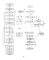
- FIG. 5 shows a flow diagram of executing reduction of a cache device, IO processing, and data promotion according to one embodiment of the present disclosure
- FIG. 6 shows a schematic diagram of a procedure for online reducing a cache device according to an embodiment of the present disclosure.
- FIG. 7 shows a structural diagram of an apparatus for online reducing a cache device according to an embodiment of the present disclosure.
- first and second are only used for distinguishing one element from another. In actuality, a first element can also be referred to as a second element, vice versa.
- terms of “comprise” and “include” are only used to state existence of the features, elements, functions or components as stated, but do not exclude existence of one or more other features, elements, functions or components.
- Cache is a component in a storage system.
- a component improves system performance by transparently storing data in a cache medium (e.g., a Flash disk).
- a flash disk cache can provide fast cache and has a higher performance than a hard disk driver (HDD).
- HDD hard disk driver
- the fast cache is a 2 nd -layer cache in VNX serial products (e.g., VNX2, VNXe) of EMCTM.
- VNX serial products e.g., VNX2, VNXe
- FIG. 1 a general view of a block data path software stack is schematically shown in FIG. 1 .
- I/O input output
- a storage system e.g., disk array
- DRAM cache hit the DRAM cache will firstly search all data cached therein; if the DRAM cache search hits, i.e., data corresponding to the IO request have already been cached in the DRAM, then the DRAM cache will use the cached data to respond to the IO request from the host; if the DRAM cache search misses, the IO request will be forwarded to the fast cache, e.g., flash disk cache.
- the fast cache e.g., flash disk cache.
- Fast cache hit when the DRAM forwards the IO request to the fast cache, the fast cache will search data cached therein. If the search hits, the fast cache will use the cached data to respond to the IO request; if the search misses, i.e., data corresponding to the IO request is not found in the fast cache, the fast cache may forward the IO request to a HDD matrix, for reading corresponding data from the HDD.
- the user's IO request be forwarded to the HDD (e.g., independent disk redundant array (RAID), multi-core RAID (MCR)), and data are read from or written to the HDD.
- the HDD e.g., independent disk redundant array (RAID), multi-core RAID (MCR)
- a first aspect of the present disclosure provides a method of online reducing cache devices from a cache, the cache including a first cache device and a second cache device, the method comprising: keeping the cache and the second cache device in an enabled state; labeling the first cache device as a to-be-reduced device so as to block a new data page from being promoted to the first cache device; removing a cached data page from the first cache device; removing cached input output (IO) historical information from the first cache device; and removing the first cache device from the cache.
- IO input output
- the cache may include a cache page Hash table that has a first link to a cached data page in the first cache device and a second link to a cached data page in the second cache device; and wherein keeping the cache and the second cache device in an enabled state comprises keeping the second link; wherein removing the cached data page from the first cache device comprises disconnecting the first link and flushing the cached data page in the first cache device to another storage device than the cache.
- the cache may comprise a cache page hash table that has a third link to a shadow page cached in the first cache device and a fourth link to a cached shadow page in the second cache device; the shadow pages have IO historical information of corresponding cache devices; and wherein keeping the cache and the second cache device in an enabled state comprises keeping the fourth link; wherein removing the cached IO historical information from the first cache device comprises disconnecting the third link and removing the shadow page cached in the first cache device.
- the cache may comprise a cache page hash table that has a fifth link to cache page metadata in the first cache device and a sixth link to cache page metadata in the second cache device;
- the cache page metadata store a mapping relationship between a data page cached in a corresponding cache device and a data page cached in another storage device than the cache; and wherein keeping the cache and the second cache device in an enabled state comprises keeping the sixth link; wherein removing the cached data page from the first cache device comprises disconnecting the fifth link and removing the cache page metadata in the first cache device.
- the cache may comprise a global shadow list that has a seventh link to a shadow page cached in the first cache device and an eighth link to a shadow page cached in the second cache device; the shadow pages having IO historical information of the corresponding cache devices; and wherein keeping the cache and the second cache device in an enabled state comprises keeping the eighth link; wherein removing the cached IO historical information from the first cache device comprises disconnecting the seventh link and removing the shadow page cached in the first cache device.
- the method may further comprise: releasing a memory for the first cache device and returning the memory to a RAM managing unit, after removing the cached data page and the cached IO historical information from the first cache device.
- one of the first cache device and the second cache device comprises a pair of solid-state disk (SSD).
- the other storage device than the cache may comprise a hard disk driver (HDD).
- the method may further comprise: searching the cache for an IO request during reducing a cache device from the cache, and if the first cache device has been labeled as a to-be-reduced device and it is found through search that a first data page associated with the IO request is cached in the first cache device, reading the first data page from the first cache device and transmitting a response to an upper layer.
- the method may further comprise: searching the cache for an IO request during reducing a cache device from the cache, and if the first cache device has been labeled as a to-be-reduced device and times of the search hitting a shadow page of the first cache device reaches a promotion threshold, wherein the shadow page has IO historical information of the first cache device, promoting the data associated with the IO request to the cache using an idle page in another cache device that is unlabeled as the to-be-reduced device in the cache.
- promoting the data associated with the IO request to the cache using an idle page in another cache device that is unlabeled as the to-be-reduced device in the cache includes: adding the data associated with the IO request into a promotion queue; searching, in the cache, a cache device that is unlabeled as a to-be-reduced device and has an idle page; obtaining to-be-promoted data from the promotion queue according to a predetermined sequence; and promoting the obtained data to the cache using the searched cache device.
- a second aspect of the present disclosure provides an apparatus for online reducing cache devices from a cache, the cache including a first cache device and a second cache device, the apparatus comprising: an enable-keeping unit configured to keep the cache and the second cache device in an enabled state; a labeling unit configured to label the first cache device as a to-be-reduced device so as to block a new data page from being promoted to the first cache device; a data page removing unit configured to remove a cached data page from the first cache device; a historical information removing unit configured to remove cached input output (IO) historical information from the first cache device; and a cache device removing unit configured to remove the first cache device from the cache.
- IO input output
- the cache may include a cache page Hash table that has a first link to a cached data page in the first cache device and a second link to a cached data page in the second cache device; and the enable-keeping unit may be configured to keep the second link; the data page removing unit may be configured to disconnect the first link and flush the cached data page in the first cache device to another storage device than the cache.
- the cache may comprise a cache page hash table that has a third link to a shadow page cached in the first cache device and a fourth link to a shadow page cached in the second cache device; the shadow pages having IO historical information of corresponding cache devices; and the enable-keeping unit may be configured to keep the fourth link; and the historical information removing unit may be configured to disconnect the third link and remove the shadow page cached in the first cache device.
- the cache may comprise a cache page hash table that has a fifth link to cache page metadata in the first cache device and a sixth link to cache page metadata in the second cache device;
- the cache page metadata store a mapping relationship between a cached data page in a corresponding cache device and a cached data page in another storage device than the cache; and the enable-keeping unit may be configured to keep the sixth link;
- the data page removing unit may be configured to disconnect the fifth link and remove the cache page metadata in the first cache device.
- the cache may comprise a global shadow list that has a seventh link to a shadow page cached in the first cache device and an eighth link to a shadow page cached in the second cache device; the shadow pages having IO historical information of the corresponding cache devices; and the enable-keeping unit may be configured to keep the eighth link; the historical information removing unit may be configured to disconnect the seventh link and remove the shadow page cached in the first cache device.
- the apparatus may further comprise: a memory releasing unit configured to release a memory for the first cache device and return the memory to a memory managing unit, after the data page removing unit removes the cached data page from the first cache device and the historical information removing unit removes the cached IO historical information from the first cache device.
- a memory releasing unit configured to release a memory for the first cache device and return the memory to a memory managing unit, after the data page removing unit removes the cached data page from the first cache device and the historical information removing unit removes the cached IO historical information from the first cache device.
- one of the first cache device and the second cache device comprises a pair of solid-state disk (SSD).
- the other storage device than the cache may comprise a hard disk driver (HDD).
- the apparatus may further comprise: a searching unit configured to search the cache for an IO request during reducing a cache device from the cache, and a hit processing unit configured to read a first data page from the first cache device and transmit a response to an upper layer, if the first cache device has been labeled as a to-be-reduced device and it is found through search that the first data page associated with the IO request is cached in the first cache device.
- a searching unit configured to search the cache for an IO request during reducing a cache device from the cache
- a hit processing unit configured to read a first data page from the first cache device and transmit a response to an upper layer, if the first cache device has been labeled as a to-be-reduced device and it is found through search that the first data page associated with the IO request is cached in the first cache device.
- the apparatus may further comprise: a searching unit configured to search the cache for an IO request during reducing a cache device from the cache, and a hit processing unit configured to: promote the data associated with the IO request to the cache using an idle page in another cache device that is unlabeled as the to-be-reduced device in the cache, if the first cache device has been labeled as a to-be-reduced device and times of the search hitting the shadow page of the first cache device reaches a promotion threshold, wherein the shadow page has IO historical information of the cache device.
- the hit processing unit may further comprise: a queuing unit configured to add the data associated with the IO request into a promotion queue; an idle page searching unit configured to search, in the cache, a cache device that is unlabeled as a to-be-reduced device and has an idle page; a scheduling unit configured to obtain to-be-promoted data from the promotion queue according to a predetermined sequence; and a promoting unit configured to promote the obtained data to the cache using the searched cache device.
- a queuing unit configured to add the data associated with the IO request into a promotion queue
- an idle page searching unit configured to search, in the cache, a cache device that is unlabeled as a to-be-reduced device and has an idle page
- a scheduling unit configured to obtain to-be-promoted data from the promotion queue according to a predetermined sequence
- a promoting unit configured to promote the obtained data to the cache using the searched cache device.
- a third aspect of the present disclosure provides a storage system, comprising any apparatus according to the second aspect.
- FIG. 2 shows a structural diagram of a fast cache.
- the fast cache includes a cache device 0 and a cache device 1 .
- RAIDs 1 configured with a pair of solid-state disk (SSD) are provided to the fast cache as a RAID group.
- the fast cache will process this pair of SSD disks as one device (cache device 0 or cache device 1 ).
- the cache device 0 and the cache device 1 may be used for storing user's hot data.
- Each cached data page has corresponding metadata.
- the metadata may store mapping information between a data page in the SSD and a data page in, for example, an HDD, and indicate whether the data page is dirty, wherein the page is a unit for data storage. If the data page in the SSD is a data page which has been copied and the data page in the SSD is the latest, it is believed that the data page is dirty.
- Each cache device in FIG. 2 can cache a certain amount of data pages, e.g., can cache N pages. Therefore, the fast cache will assign N shadow pages for tracking IO historical information that is not stored in the SSD. As shown in FIG. 2 , suppose the cache device 0 can cache N pages, and it is assigned N cache pages metadata and N shadow pages. Similarly, the other cache device in the fast cache also has its own cached data pages and shadow pages.
- the data pages, data page metadata, and shadow pages of all devices may be linked to a cache page hash table, while the shadow pages of all devices may be similarly linked to a global shadow list.
- the cache page hash table and the global shadow list are used for mapping key values to corresponding positions so as to access the data page or shadow page records.
- the cache may also have an idle list for each cache device to indicate idle pages in the corresponding cache device.
- a prior fast cache design when a user wants to delete a certain cache device (e.g., SSD) from the fast cache because the cache device is not sufficiently utilized, the user has to destroy the fast cache and then rebuilds the fast cache using less cache devices.
- This design means that hot data in the fast cache will be lost when a certain cache device is deleted; and after the fast cache is rebuilt, a long time needs to be taken for pre-warming before restart. Therefore, during deletion/creation of the fast cache, the fast cache cannot be used, and a user cannot obtain any benefit from the fast cache. Even worse, this process will affect the overall performance of a storage system (e.g., an array), because more internal IOs will be generated during the deleting/creating/pre-warming processing of the fast cache, which decreases the resources for external IO processing.
- a storage system e.g., an array
- FIG. 3 which incorporates FIGS. 3A and 3B , shows an example of a processing procedure for reducing cache devices according to a prior design.
- removing the cache device 1 will have to destroy an entire cache. That is, although only the cache device 1 is to be reduced, the cache device 0 will also be affected and cannot work.
- the cache in order to remove the cache device 1 , the cache will be first set to a destroyed state, and then cached data pages in the cache device 0 and cache device 1 will be flushed into an HDD (e.g., MCR). Afterwards, a memory for the two cache devices will be returned to a DRAM cache. Then the cache is rebuilt using the cache device 0 .
- HDD e.g., MCR
- the cache device 0 When the cache has just been built, the cache device 0 cannot be used immediately, until completion of the pre-warming procedure. For example, it is needed to re-request a memory for the cache device 0 from the DRAM. The procedure of destroying and rebuilding will seriously affect the overall performance of the storage system.
- the present disclosure provides a method and apparatus for online reducing cache devices from a cache.
- FIG. 4 a a flow chart of a method of online reducing cache devices according to the embodiments of the present disclosure is presented.
- the method may be used for online removing a cache device from the fast cache shown in FIG. 1 or FIG. 2 , while maintaining the fast cache in a serving state (i.e., an enabled state).
- a serving state i.e., an enabled state.
- the embodiments of the present disclosure are not limited to removing a cache device from the specific fast cache shown in FIG. 1 and FIG. 2 ; instead, they may be applied more broadly to remove a cache device from any cache that includes at least a first cache device and a second cache device.
- the method comprises: keeping the cache and the second cache device in an enabled state (S 410 ); labeling a first cache device as a to-be-reduced device so as to block a new data page from being promoted to the first cache device (S 420 ); removing a cached data page from the first cache device (S 430 ); removing cached input output ( 10 ) historical information from the first cache device (S 440 ); and removing the first cache device from the cache (S 450 ).
- a cache device can be removed without affecting other cache devices of the cache, obviating a need of destroying the entire cache and then rebuilding it. Therefore, according to the embodiments of the present disclosure, the overall performance of the storage system can be enhanced and user experience can be improved.
- the embodiments of the present disclosure are not limited to removing a single cache device from the cache; instead, it can remove a plurality of cache devices using a similar principle.
- the cache may comprise other cache devices than the first cache device and the second cache device, and except the cache device being reduced, other cache devices might not be affected during the process of reducing the cache device.
- the first cache device or the second cache device in the cache may comprise one or more pairs of SSDs.
- the embodiments of the present disclosure are not limited thereto. Actually, implementation of the embodiments of the present disclosure is not limited to a cache device of any specific structure.
- the cache may be a fast cache like what is shown in FIG. 2 .
- the cache may comprise a cache page hash table that has a first link to a data page cached in the first cache device and a second link to a data page cached in the second cache device.
- the method 400 may comprise: keeping a second link at the block S 410 so as to keep the cache and the second cache device in an enabled state; in addition, at block S 430 , the first link may be disconnected, and the data page cached in the first cache device may be flushed to another storage device (e.g., HDD, MCR) other than the cache.
- another storage device e.g., HDD, MCR
- the cache may comprise a cache page hash table that has a third link to a shadow page cached in the first cache device, and a fourth link to a shadow page cached in the second cache device, wherein the shadow pages has IO historical information of corresponding cache devices.
- the method 400 may include keeping the fourth link at block S 410 so as to keep the cache and the second cache device in an enabled state; in addition, at block S 440 , a third link may be disconnected, and the shadow page (i.e., corresponding IO historical information) cached in the first cache device is removed.
- the cache may comprise a cache page hash table that has a fifth link to cache page metadata in the first cache device, and a sixth link to a cache page metadata in the second cache device; the cache page metadata stores a mapping relationship between the data page cached in a corresponding cache device and a data page stored in another storage device (e.g., HDD, MCR).
- the method 400 may comprise keeping the sixth link at block S 410 ; in addition, at block S 430 , the fifth link may be disconnected, and the cache page metadata in the first cache device is removed.
- the cache includes a global shadow list similar as that shown in FIG. 2 , global shadow list having a seventh link to a shadow page cached in the first cache device and an eighth link to the shadow page cached in the second cache device; the shadow page has IO historical information of a corresponding cache device.
- the method 400 may comprise keeping the eighth link at the block S 410 ; in addition, at block S 440 , the seventh link may be disconnected to remove the shadow page cached in the first cache device.
- the method 400 may comprise: releasing (S 460 ) a memory (e.g., RAM) for the first cache device, and returns the memory to a memory managing unit, after removing the cached data page and the cached IO historical information from the first cache device.
- a memory e.g., RAM
- This embodiment enables re-allocation of the memory occupied by the first cache device, thereby enhancing utilization of the memory.
- the method 400 may further comprise performing IO processing during reducing a cache device from the cache.
- the method 400 may comprise: searching (S 470 ) the cache for an IO request during reducing a cache device from the cache; if the first cache device has been labeled as a to-be-reduced device and it is found through the search that a first data page associated with the IO request is cached in the first cache device, then reading, from the first cache device, the first data page and transmitting a response (S 480 ) to an upper layer.
- the search hit likely occurs.
- flushing of the cache page in the first cache device is being performed, with more and more cache pages being flushed and with the metadata of the cached data page are gradually flushed from the fast cache hash table, the possibility of a search hitting a cache data page in the first cache device will be decreased.
- the fast cache hash table does not have a link to the cache data page of the cache device anymore, and the user IO will not hit the first cache device any longer.
- the first cache device has been labeled as to-be-reduced device and the search in block S 470 hits a shadow page of the first cache device and the number of hits reaches a promotion threshold
- data associated with the IO request may be promoted to the cache (S 480 ) using an idle page of another cache device (e.g., the second cache device) that is unlabeled as a to-be-reduced device in the cache.
- the shadow page has IO historical information of the first cache device. As the first cache device's shadow page starts being removed from the global shadow list, the opportunity of search hitting the shadow page in the first cache device being reduced will be lowered. When the first cache device's entire shadow page is removed from the global shadow list, there will be no opportunity to make the user IO hit a shadow element in the first cache device.
- FIG. 4 b shows an example embodiment of the operation at the block S 480 .
- block S 480 may comprise:
- the embodiments of the present disclosure are not limited to any specific implementation to carry out the hit processing at block S 480 .
- the data promoting process is not necessarily based on a queue; instead, a priority of data promotion may be determined based on other factors.
- the idle page search at block S 482 may also be omitted; instead, the data will be promoted to a predetermined cache device.
- FIG. 5 shows a flow of performing reduction of cache devices, IO processing, and data promotion, as well as relationships between respective operations according to one embodiment of the present disclosure.
- a state of the to-be-reduced device may be set as “to be reduced,” or “to be removed,” so as to avoid promoting new data pages to the cache device.
- State of the device may be a newly added attribute for the device object.
- the cached data page therein may be moved into the HDD, till the cache data page is empty.
- a link to the cache data page may be disconnected from the cache hash table, i.e., removing the cache data page from the cache hash table.
- similar processing may be performed to the shadow page in the cache device, i.e., removing the shadow page from the hash table and the global shadow list.
- the cache device may be removed from the cache.
- a memory corresponding to the cache device may be returned to a memory managing unit and the SSD in the cache device may be removed.
- FIG. 5 also shows an example flow of performing IO to the cache.
- the flow comprises finding whether a cache page in the cache is hit by searching a hash table. Moreover, when hitting a shadow page, determine whether to promote corresponding data to the cache based on the times of hits.
- FIG. 5 shows a specific example of promoting corresponding data to the cache.
- a promotion queue is utilized. This operation is similar to the flow shown in FIG. 4 b , which will not be detailed here.
- FIG. 6 shows state changes of the cache and the cache devices therein when reducing a cache device from the cache according to one embodiment of the present disclosure.
- the state of the device 1 is labeled as “to be reduced,” while the cache is always in an enabled state, which forms a distinct contrast with the states shown in FIG. 3 .
- Another difference from FIG. 3 lies in that in FIG. 6 , only cache pages associated with the “to-be-reduced” device (device 1 in this example) are flushed to the MCR, without affecting the cached data of another cache device (device 0 in this example). In other words, the status of another cache device is maintained unchanged. For example, during the device 1 is being reduced, data can still be promoted to device 0 .
- FIG. 7 shows an example structure diagram of an apparatus 700 according to the embodiments of the present disclosure.
- the apparatus 700 is for online reducing a cache device from the cache.
- the apparatus may be implemented as a component in a storage system.
- the apparatus is operable for carrying out the method 400 described with reference to FIGS. 4 a - 6 and any other processing and method. It should be understood that the method 400 is not limited to being executed by the apparatus 700 ; at least some blocks of the method 400 may also be carried out by other apparatus or entity.
- the cache at least comprises a first cache device and a second cache device.
- the apparatus 700 comprises an enable-keeping unit 710 configured to keep the cache and the second cache device in an enabled state; a labeling unit 720 configured to label the first cache device as a to-be-reduced device so as to block a new data page from being promoted to the first cache device; a data page removing unit 730 configured to remove the cached data page from the first cache device; a historical information removing unit 740 configured to remove the cached input output (IO) historical information from the first cache device; and a cache device removing unit 750 configured to remove the first cache device from the cache.
- IO input output
- units 710 - 750 can be configured to perform operations of blocks S 410 -S 450 of the method 400 described with reference to FIGS. 4 a - 6 , respectively. Therefore, the depiction about blocks S 410 -S 450 are likewise applicable to units 710 - 750 . Therefore, specific details will not be repeated.
- the apparatus 700 may further comprise: a memory releasing unit 760 configured to release a memory for the first cache device and return the memory to a memory managing unit, after the data page removing unit removes the cached data page from the first cache device and the historical information removing unit removes the cached IO historical information from the first cache device.
- a memory releasing unit 760 configured to release a memory for the first cache device and return the memory to a memory managing unit, after the data page removing unit removes the cached data page from the first cache device and the historical information removing unit removes the cached IO historical information from the first cache device.
- the apparatus 700 may comprise a searching unit 770 configured to search the cache for an IO request during reducing a cache device from the cache, and a hit processing unit 780 configured to, if the first cache device has been labeled as a to-be-reduced device and it is found through the search that the first data page associated with the IO request is cached in the first cache device, read the first data page from the first cache device and transmit a response to an upper layer.
- a searching unit 770 configured to search the cache for an IO request during reducing a cache device from the cache
- a hit processing unit 780 configured to, if the first cache device has been labeled as a to-be-reduced device and it is found through the search that the first data page associated with the IO request is cached in the first cache device, read the first data page from the first cache device and transmit a response to an upper layer.
- the hit processing unit 780 may also be configured to: if the first cache device has been labeled as a to-be-reduced device and times of the search hitting the shadow page of the first cache device reaches a promotion threshold, wherein the shadow page has IO historical information of the cache device, promote the data associated with the IO request to the cache using an idle page in another cache device that is unlabeled as a to-be-reduced device in the cache.
- the hit processing unit 780 may further comprise: a queuing unit 781 configured to add the data associated with the IO request into a promotion queue; an idle page searching unit 782 configured to search, in the cache, a device that is unlabeled as a to-be-reduced device has an idle page; a scheduling unit 783 configured to obtain to-be-promoted data from the promotion queue according to a predetermined sequence; and a promoting unit 784 configured to promote the obtained data to the cache using the searched cache device.
- the embodiments of the present disclosure are not limited to any specific embodiments to implement the hit processing unit 780 .
- the promoting procedure is not necessarily based on a queue; instead, priority of data promotion may be determined based on other factors.
- the idle page searching unit 782 may also be omitted; instead, the data are promoted to a predetermined cache device.
- apparatus 700 may also comprise other units that are not shown in FIG. 7 .
- Embodiments of the present disclosure can achieve at least one of the following advantages. It is possible to reduce a cache device in an online fashion without affecting the cache to serve user IO. Moreover, the procedure of reducing a cache device is not destructive, and has little impacts on the storage system. In addition, internal 10 is reduced and the overall performance is enhanced.
- some embodiments also intend to cover a program storage device, e.g., a digital data storage medium, which is machine or computer-readable and coded machine-executable or computer-executable instruction programs, wherein the instruction performs some or all steps of the method above.
- the program storage device may be, for example, a digital memory, a magnetic storage medium such as a disk and a tape, a hard disk driver or an optical-readable digital data storage medium.
- the embodiment also intends to cover a computer programmed to execute steps of the method above.
- an apparatus comprising a memory and a processor.
- the memory comprises instructions.
- the apparatus is operable to perform any method as described with reference to FIGS. 4 a - 6 .
- Functions of the processor therein may be provided by a single dedicated processor, a single shared processor, or a plurality of individual processors.
- processor may include, but not limited to, digital signal processor (DSP) hardware, network processor, an application-specific integrated circuit (ASIC), a field programmable gate array (FPGA), a read-only memory (ROM) for storing software, a random access memory (RAM) and a non-volatile memory. It may also comprise other conventional and/or customized hardware.
- DSP digital signal processor
- ASIC application-specific integrated circuit
- FPGA field programmable gate array
- ROM read-only memory
- RAM random access memory
- non-volatile memory non-volatile memory
Abstract
Description
Claims (19)
Applications Claiming Priority (3)
| Application Number | Priority Date | Filing Date | Title |
|---|---|---|---|
| CN201510609728.9A CN106547477B (en) | 2015-09-22 | 2015-09-22 | Method and apparatus for reducing buffer memory device online |
| CN201510609728 | 2015-09-22 | ||
| CNCN201510609728.9 | 2015-09-22 |
Publications (2)
| Publication Number | Publication Date |
|---|---|
| US20170103020A1 US20170103020A1 (en) | 2017-04-13 |
| US10387308B2 true US10387308B2 (en) | 2019-08-20 |
Family
ID=58364343
Family Applications (1)
| Application Number | Title | Priority Date | Filing Date |
|---|---|---|---|
| US15/268,801 Active 2037-03-28 US10387308B2 (en) | 2015-09-22 | 2016-09-19 | Method and apparatus for online reducing caching devices |
Country Status (2)
| Country | Link |
|---|---|
| US (1) | US10387308B2 (en) |
| CN (1) | CN106547477B (en) |
Cited By (2)
| Publication number | Priority date | Publication date | Assignee | Title |
|---|---|---|---|---|
| US10761989B2 (en) | 2017-06-30 | 2020-09-01 | EMC IP Holding Company LLC | Method of storage management, storage system and computer program product |
| US11593272B2 (en) | 2018-10-31 | 2023-02-28 | EMC IP Holding Company LLC | Method, apparatus and computer program product for managing data access |
Families Citing this family (3)
| Publication number | Priority date | Publication date | Assignee | Title |
|---|---|---|---|---|
| CN110413545B (en) * | 2018-04-28 | 2023-06-20 | 伊姆西Ip控股有限责任公司 | Storage management method, electronic device, and computer program product |
| TWI725791B (en) * | 2019-01-16 | 2021-04-21 | 香港商希瑞科技股份有限公司 | Server and associated computer program product |
| TWI692955B (en) | 2019-01-16 | 2020-05-01 | 香港商希瑞科技股份有限公司 | Server and associated computer program product |
Citations (14)
| Publication number | Priority date | Publication date | Assignee | Title |
|---|---|---|---|---|
| US6633967B1 (en) * | 2000-08-31 | 2003-10-14 | Hewlett-Packard Development Company, L.P. | Coherent translation look-aside buffer |
| US6701393B1 (en) * | 2002-06-27 | 2004-03-02 | Emc Corporation | Systems and methods for managing storage location descriptors |
| US20060004860A1 (en) * | 2004-05-24 | 2006-01-05 | Antti-Pekka Liedes | Method for checkpointing a main-memory database |
| US7676554B1 (en) * | 2005-09-15 | 2010-03-09 | Juniper Networks, Inc. | Network acceleration device having persistent in-memory cache |
| US20110082962A1 (en) * | 2009-10-01 | 2011-04-07 | Vmware, Inc. | Monitoring a data structure in a virtual machine |
| US20110106804A1 (en) * | 2009-11-04 | 2011-05-05 | Seagate Technology Llc | File management system for devices containing solid-state media |
| US20110145489A1 (en) * | 2004-04-05 | 2011-06-16 | Super Talent Electronics, Inc. | Hybrid storage device |
| US20130132681A1 (en) * | 2011-11-22 | 2013-05-23 | Microsoft Corporation | Temporal standby list |
| US20130159662A1 (en) * | 2011-12-14 | 2013-06-20 | Microsoft Corporation | Working Set Swapping Using a Sequentially Ordered Swap File |
| US20130205089A1 (en) * | 2012-02-08 | 2013-08-08 | Mediatek Singapore Pte. Ltd. | Cache Device and Methods Thereof |
| US8607208B1 (en) * | 2008-10-01 | 2013-12-10 | Oracle International Corporation | System and methods for object code hot updates |
| US20140325145A1 (en) * | 2013-04-26 | 2014-10-30 | Lsi Corporation | Cache rebuilds based on tracking data for cache entries |
| US20140379959A1 (en) * | 2013-06-25 | 2014-12-25 | Lsi Corporation | Map recycling acceleration |
| US20160210044A1 (en) * | 2015-01-15 | 2016-07-21 | Commvault Systems, Inc. | Intelligent hybrid drive caching |
Family Cites Families (3)
| Publication number | Priority date | Publication date | Assignee | Title |
|---|---|---|---|---|
| US6470436B1 (en) * | 1998-12-01 | 2002-10-22 | Fast-Chip, Inc. | Eliminating memory fragmentation and garbage collection from the process of managing dynamically allocated memory |
| US7979509B1 (en) * | 2005-09-15 | 2011-07-12 | Juniper Networks, Inc. | Clustered network acceleration devices having shared cache |
| US9110813B2 (en) * | 2013-02-14 | 2015-08-18 | Avago Technologies General Ip (Singapore) Pte Ltd | Cache load balancing in storage controllers |
-
2015
- 2015-09-22 CN CN201510609728.9A patent/CN106547477B/en active Active
-
2016
- 2016-09-19 US US15/268,801 patent/US10387308B2/en active Active
Patent Citations (14)
| Publication number | Priority date | Publication date | Assignee | Title |
|---|---|---|---|---|
| US6633967B1 (en) * | 2000-08-31 | 2003-10-14 | Hewlett-Packard Development Company, L.P. | Coherent translation look-aside buffer |
| US6701393B1 (en) * | 2002-06-27 | 2004-03-02 | Emc Corporation | Systems and methods for managing storage location descriptors |
| US20110145489A1 (en) * | 2004-04-05 | 2011-06-16 | Super Talent Electronics, Inc. | Hybrid storage device |
| US20060004860A1 (en) * | 2004-05-24 | 2006-01-05 | Antti-Pekka Liedes | Method for checkpointing a main-memory database |
| US7676554B1 (en) * | 2005-09-15 | 2010-03-09 | Juniper Networks, Inc. | Network acceleration device having persistent in-memory cache |
| US8607208B1 (en) * | 2008-10-01 | 2013-12-10 | Oracle International Corporation | System and methods for object code hot updates |
| US20110082962A1 (en) * | 2009-10-01 | 2011-04-07 | Vmware, Inc. | Monitoring a data structure in a virtual machine |
| US20110106804A1 (en) * | 2009-11-04 | 2011-05-05 | Seagate Technology Llc | File management system for devices containing solid-state media |
| US20130132681A1 (en) * | 2011-11-22 | 2013-05-23 | Microsoft Corporation | Temporal standby list |
| US20130159662A1 (en) * | 2011-12-14 | 2013-06-20 | Microsoft Corporation | Working Set Swapping Using a Sequentially Ordered Swap File |
| US20130205089A1 (en) * | 2012-02-08 | 2013-08-08 | Mediatek Singapore Pte. Ltd. | Cache Device and Methods Thereof |
| US20140325145A1 (en) * | 2013-04-26 | 2014-10-30 | Lsi Corporation | Cache rebuilds based on tracking data for cache entries |
| US20140379959A1 (en) * | 2013-06-25 | 2014-12-25 | Lsi Corporation | Map recycling acceleration |
| US20160210044A1 (en) * | 2015-01-15 | 2016-07-21 | Commvault Systems, Inc. | Intelligent hybrid drive caching |
Cited By (2)
| Publication number | Priority date | Publication date | Assignee | Title |
|---|---|---|---|---|
| US10761989B2 (en) | 2017-06-30 | 2020-09-01 | EMC IP Holding Company LLC | Method of storage management, storage system and computer program product |
| US11593272B2 (en) | 2018-10-31 | 2023-02-28 | EMC IP Holding Company LLC | Method, apparatus and computer program product for managing data access |
Also Published As
| Publication number | Publication date |
|---|---|
| CN106547477B (en) | 2019-07-19 |
| US20170103020A1 (en) | 2017-04-13 |
| CN106547477A (en) | 2017-03-29 |
Similar Documents
| Publication | Publication Date | Title |
|---|---|---|
| US10387308B2 (en) | Method and apparatus for online reducing caching devices | |
| US10860493B2 (en) | Method and apparatus for data storage system | |
| US20200150890A1 (en) | Data Deduplication Method and Apparatus | |
| US8751763B1 (en) | Low-overhead deduplication within a block-based data storage | |
| WO2016107485A1 (en) | Read cache management method and device based on solid state drive | |
| US11593272B2 (en) | Method, apparatus and computer program product for managing data access | |
| CN110109915B (en) | Method, apparatus and computer program product for managing hash tables | |
| CN109800185B (en) | Data caching method in data storage system | |
| US9405643B2 (en) | Multi-level lookup architecture to facilitate failure recovery | |
| KR20120090965A (en) | Apparatus, system, and method for caching data on a solid-state strorage device | |
| US10303374B2 (en) | Data check method and storage system | |
| CN105843551A (en) | Data integrity and loss resistance in high performance and high capacity storage deduplication | |
| KR101779174B1 (en) | Data discard method for journaling filesystem and memory management apparatus thereof | |
| CN102710763B (en) | The method and system of a kind of distributed caching pond, burst and Failure Transfer | |
| EP3316150A1 (en) | Method and apparatus for file compaction in key-value storage system | |
| JP2017126334A (en) | Storage devices, operating methods thereof and systems | |
| US10719240B2 (en) | Method and device for managing a storage system having a multi-layer storage structure | |
| CN112799595A (en) | Data processing method, device and storage medium | |
| US11194720B2 (en) | Reducing index operations in a cache | |
| CN104035822A (en) | Low-cost efficient internal storage redundancy removing method and system | |
| US9645946B2 (en) | Encryption for solid state drives (SSDs) | |
| US20150212847A1 (en) | Apparatus and method for managing cache of virtual machine image file | |
| US11775194B2 (en) | Data storage method and apparatus in distributed storage system, and computer program product | |
| US9063656B2 (en) | System and methods for digest-based storage | |
| KR102403063B1 (en) | Mobile device and management method of mobile device |
Legal Events
| Date | Code | Title | Description |
|---|---|---|---|
| AS | Assignment |
Owner name: EMC IP HOLDING COMPANY LLC, MASSACHUSETTS Free format text: ASSIGNMENT OF ASSIGNORS INTEREST;ASSIGNORS:XU, XINLEI;LI, LIAM XIONGCHENG;GAO, JIAN;AND OTHERS;REEL/FRAME:040398/0319 Effective date: 20161122 |
|
| AS | Assignment |
Owner name: THE BANK OF NEW YORK MELLON TRUST COMPANY, N.A., AS COLLATERAL AGENT, TEXAS Free format text: PATENT SECURITY AGREEMENT (NOTES);ASSIGNORS:DELL PRODUCTS L.P.;EMC CORPORATION;EMC IP HOLDING COMPANY LLC;REEL/FRAME:043775/0082 Effective date: 20170829 Owner name: CREDIT SUISSE AG, CAYMAN ISLANDS BRANCH, AS COLLATERAL AGENT, NORTH CAROLINA Free format text: PATENT SECURITY AGREEMENT (CREDIT);ASSIGNORS:DELL PRODUCTS L.P.;EMC CORPORATION;EMC IP HOLDING COMPANY LLC;REEL/FRAME:043772/0750 Effective date: 20170829 Owner name: CREDIT SUISSE AG, CAYMAN ISLANDS BRANCH, AS COLLAT Free format text: PATENT SECURITY AGREEMENT (CREDIT);ASSIGNORS:DELL PRODUCTS L.P.;EMC CORPORATION;EMC IP HOLDING COMPANY LLC;REEL/FRAME:043772/0750 Effective date: 20170829 Owner name: THE BANK OF NEW YORK MELLON TRUST COMPANY, N.A., A Free format text: PATENT SECURITY AGREEMENT (NOTES);ASSIGNORS:DELL PRODUCTS L.P.;EMC CORPORATION;EMC IP HOLDING COMPANY LLC;REEL/FRAME:043775/0082 Effective date: 20170829 |
|
| STPP | Information on status: patent application and granting procedure in general |
Free format text: PUBLICATIONS -- ISSUE FEE PAYMENT VERIFIED |
|
| AS | Assignment |
Owner name: THE BANK OF NEW YORK MELLON TRUST COMPANY, N.A., T Free format text: SECURITY AGREEMENT;ASSIGNORS:CREDANT TECHNOLOGIES, INC.;DELL INTERNATIONAL L.L.C.;DELL MARKETING L.P.;AND OTHERS;REEL/FRAME:049452/0223 Effective date: 20190320 Owner name: THE BANK OF NEW YORK MELLON TRUST COMPANY, N.A., TEXAS Free format text: SECURITY AGREEMENT;ASSIGNORS:CREDANT TECHNOLOGIES, INC.;DELL INTERNATIONAL L.L.C.;DELL MARKETING L.P.;AND OTHERS;REEL/FRAME:049452/0223 Effective date: 20190320 |
|
| STCF | Information on status: patent grant |
Free format text: PATENTED CASE |
|
| AS | Assignment |
Owner name: THE BANK OF NEW YORK MELLON TRUST COMPANY, N.A., TEXAS Free format text: SECURITY AGREEMENT;ASSIGNORS:CREDANT TECHNOLOGIES INC.;DELL INTERNATIONAL L.L.C.;DELL MARKETING L.P.;AND OTHERS;REEL/FRAME:053546/0001 Effective date: 20200409 |
|
| AS | Assignment |
Owner name: EMC IP HOLDING COMPANY LLC, TEXAS Free format text: RELEASE OF SECURITY INTEREST IN PATENTS PREVIOUSLY RECORDED AT REEL/FRAME (043775/0082);ASSIGNOR:THE BANK OF NEW YORK MELLON TRUST COMPANY, N.A., AS NOTES COLLATERAL AGENT;REEL/FRAME:060958/0468 Effective date: 20220329 Owner name: EMC CORPORATION, MASSACHUSETTS Free format text: RELEASE OF SECURITY INTEREST IN PATENTS PREVIOUSLY RECORDED AT REEL/FRAME (043775/0082);ASSIGNOR:THE BANK OF NEW YORK MELLON TRUST COMPANY, N.A., AS NOTES COLLATERAL AGENT;REEL/FRAME:060958/0468 Effective date: 20220329 Owner name: DELL PRODUCTS L.P., TEXAS Free format text: RELEASE OF SECURITY INTEREST IN PATENTS PREVIOUSLY RECORDED AT REEL/FRAME (043775/0082);ASSIGNOR:THE BANK OF NEW YORK MELLON TRUST COMPANY, N.A., AS NOTES COLLATERAL AGENT;REEL/FRAME:060958/0468 Effective date: 20220329 |
|
| MAFP | Maintenance fee payment |
Free format text: PAYMENT OF MAINTENANCE FEE, 4TH YEAR, LARGE ENTITY (ORIGINAL EVENT CODE: M1551); ENTITY STATUS OF PATENT OWNER: LARGE ENTITY Year of fee payment: 4 |