US10384028B2 - Nasal interface apparatus and systems for use with a respiratory assist device - Google Patents
Nasal interface apparatus and systems for use with a respiratory assist device Download PDFInfo
- Publication number
- US10384028B2 US10384028B2 US14/427,986 US201314427986A US10384028B2 US 10384028 B2 US10384028 B2 US 10384028B2 US 201314427986 A US201314427986 A US 201314427986A US 10384028 B2 US10384028 B2 US 10384028B2
- Authority
- US
- United States
- Prior art keywords
- nasal
- nasal interface
- interface apparatus
- hub
- hub assembly
- Prior art date
- Legal status (The legal status is an assumption and is not a legal conclusion. Google has not performed a legal analysis and makes no representation as to the accuracy of the status listed.)
- Active, expires
Links
Images


Classifications
-
- A—HUMAN NECESSITIES
- A61—MEDICAL OR VETERINARY SCIENCE; HYGIENE
- A61M—DEVICES FOR INTRODUCING MEDIA INTO, OR ONTO, THE BODY; DEVICES FOR TRANSDUCING BODY MEDIA OR FOR TAKING MEDIA FROM THE BODY; DEVICES FOR PRODUCING OR ENDING SLEEP OR STUPOR
- A61M16/00—Devices for influencing the respiratory system of patients by gas treatment, e.g. mouth-to-mouth respiration; Tracheal tubes
- A61M16/06—Respiratory or anaesthetic masks
- A61M16/0666—Nasal cannulas or tubing
-
- A—HUMAN NECESSITIES
- A61—MEDICAL OR VETERINARY SCIENCE; HYGIENE
- A61M—DEVICES FOR INTRODUCING MEDIA INTO, OR ONTO, THE BODY; DEVICES FOR TRANSDUCING BODY MEDIA OR FOR TAKING MEDIA FROM THE BODY; DEVICES FOR PRODUCING OR ENDING SLEEP OR STUPOR
- A61M16/00—Devices for influencing the respiratory system of patients by gas treatment, e.g. mouth-to-mouth respiration; Tracheal tubes
- A61M16/0003—Accessories therefor, e.g. sensors, vibrators, negative pressure
-
- A—HUMAN NECESSITIES
- A61—MEDICAL OR VETERINARY SCIENCE; HYGIENE
- A61M—DEVICES FOR INTRODUCING MEDIA INTO, OR ONTO, THE BODY; DEVICES FOR TRANSDUCING BODY MEDIA OR FOR TAKING MEDIA FROM THE BODY; DEVICES FOR PRODUCING OR ENDING SLEEP OR STUPOR
- A61M16/00—Devices for influencing the respiratory system of patients by gas treatment, e.g. mouth-to-mouth respiration; Tracheal tubes
- A61M16/0057—Pumps therefor
- A61M16/0063—Compressors
-
- A—HUMAN NECESSITIES
- A61—MEDICAL OR VETERINARY SCIENCE; HYGIENE
- A61M—DEVICES FOR INTRODUCING MEDIA INTO, OR ONTO, THE BODY; DEVICES FOR TRANSDUCING BODY MEDIA OR FOR TAKING MEDIA FROM THE BODY; DEVICES FOR PRODUCING OR ENDING SLEEP OR STUPOR
- A61M16/00—Devices for influencing the respiratory system of patients by gas treatment, e.g. mouth-to-mouth respiration; Tracheal tubes
- A61M16/021—Devices for influencing the respiratory system of patients by gas treatment, e.g. mouth-to-mouth respiration; Tracheal tubes operated by electrical means
- A61M16/022—Control means therefor
-
- A—HUMAN NECESSITIES
- A61—MEDICAL OR VETERINARY SCIENCE; HYGIENE
- A61M—DEVICES FOR INTRODUCING MEDIA INTO, OR ONTO, THE BODY; DEVICES FOR TRANSDUCING BODY MEDIA OR FOR TAKING MEDIA FROM THE BODY; DEVICES FOR PRODUCING OR ENDING SLEEP OR STUPOR
- A61M16/00—Devices for influencing the respiratory system of patients by gas treatment, e.g. mouth-to-mouth respiration; Tracheal tubes
- A61M16/06—Respiratory or anaesthetic masks
- A61M16/0605—Means for improving the adaptation of the mask to the patient
- A61M16/0616—Means for improving the adaptation of the mask to the patient with face sealing means comprising a flap or membrane projecting inwards, such that sealing increases with increasing inhalation gas pressure
- A61M16/0622—Means for improving the adaptation of the mask to the patient with face sealing means comprising a flap or membrane projecting inwards, such that sealing increases with increasing inhalation gas pressure having an underlying cushion
-
- A—HUMAN NECESSITIES
- A61—MEDICAL OR VETERINARY SCIENCE; HYGIENE
- A61M—DEVICES FOR INTRODUCING MEDIA INTO, OR ONTO, THE BODY; DEVICES FOR TRANSDUCING BODY MEDIA OR FOR TAKING MEDIA FROM THE BODY; DEVICES FOR PRODUCING OR ENDING SLEEP OR STUPOR
- A61M16/00—Devices for influencing the respiratory system of patients by gas treatment, e.g. mouth-to-mouth respiration; Tracheal tubes
- A61M16/06—Respiratory or anaesthetic masks
- A61M16/0666—Nasal cannulas or tubing
- A61M16/0672—Nasal cannula assemblies for oxygen therapy
- A61M16/0677—Gas-saving devices therefor
-
- A—HUMAN NECESSITIES
- A61—MEDICAL OR VETERINARY SCIENCE; HYGIENE
- A61M—DEVICES FOR INTRODUCING MEDIA INTO, OR ONTO, THE BODY; DEVICES FOR TRANSDUCING BODY MEDIA OR FOR TAKING MEDIA FROM THE BODY; DEVICES FOR PRODUCING OR ENDING SLEEP OR STUPOR
- A61M16/00—Devices for influencing the respiratory system of patients by gas treatment, e.g. mouth-to-mouth respiration; Tracheal tubes
- A61M16/10—Preparation of respiratory gases or vapours
- A61M16/12—Preparation of respiratory gases or vapours by mixing different gases
- A61M16/122—Preparation of respiratory gases or vapours by mixing different gases with dilution
- A61M16/125—Diluting primary gas with ambient air
- A61M16/127—Diluting primary gas with ambient air by Venturi effect, i.e. entrainment mixers
-
- A—HUMAN NECESSITIES
- A61—MEDICAL OR VETERINARY SCIENCE; HYGIENE
- A61M—DEVICES FOR INTRODUCING MEDIA INTO, OR ONTO, THE BODY; DEVICES FOR TRANSDUCING BODY MEDIA OR FOR TAKING MEDIA FROM THE BODY; DEVICES FOR PRODUCING OR ENDING SLEEP OR STUPOR
- A61M16/00—Devices for influencing the respiratory system of patients by gas treatment, e.g. mouth-to-mouth respiration; Tracheal tubes
- A61M16/20—Valves specially adapted to medical respiratory devices
- A61M16/201—Controlled valves
- A61M16/202—Controlled valves electrically actuated
- A61M16/203—Proportional
- A61M16/204—Proportional used for inhalation control
-
- A—HUMAN NECESSITIES
- A61—MEDICAL OR VETERINARY SCIENCE; HYGIENE
- A61M—DEVICES FOR INTRODUCING MEDIA INTO, OR ONTO, THE BODY; DEVICES FOR TRANSDUCING BODY MEDIA OR FOR TAKING MEDIA FROM THE BODY; DEVICES FOR PRODUCING OR ENDING SLEEP OR STUPOR
- A61M16/00—Devices for influencing the respiratory system of patients by gas treatment, e.g. mouth-to-mouth respiration; Tracheal tubes
- A61M16/08—Bellows; Connecting tubes ; Water traps; Patient circuits
- A61M16/0816—Joints or connectors
- A61M16/0833—T- or Y-type connectors, e.g. Y-piece
-
- A—HUMAN NECESSITIES
- A61—MEDICAL OR VETERINARY SCIENCE; HYGIENE
- A61M—DEVICES FOR INTRODUCING MEDIA INTO, OR ONTO, THE BODY; DEVICES FOR TRANSDUCING BODY MEDIA OR FOR TAKING MEDIA FROM THE BODY; DEVICES FOR PRODUCING OR ENDING SLEEP OR STUPOR
- A61M16/00—Devices for influencing the respiratory system of patients by gas treatment, e.g. mouth-to-mouth respiration; Tracheal tubes
- A61M16/08—Bellows; Connecting tubes ; Water traps; Patient circuits
- A61M16/0866—Passive resistors therefor
-
- A—HUMAN NECESSITIES
- A61—MEDICAL OR VETERINARY SCIENCE; HYGIENE
- A61M—DEVICES FOR INTRODUCING MEDIA INTO, OR ONTO, THE BODY; DEVICES FOR TRANSDUCING BODY MEDIA OR FOR TAKING MEDIA FROM THE BODY; DEVICES FOR PRODUCING OR ENDING SLEEP OR STUPOR
- A61M16/00—Devices for influencing the respiratory system of patients by gas treatment, e.g. mouth-to-mouth respiration; Tracheal tubes
- A61M16/0003—Accessories therefor, e.g. sensors, vibrators, negative pressure
- A61M2016/0015—Accessories therefor, e.g. sensors, vibrators, negative pressure inhalation detectors
- A61M2016/0018—Accessories therefor, e.g. sensors, vibrators, negative pressure inhalation detectors electrical
- A61M2016/0021—Accessories therefor, e.g. sensors, vibrators, negative pressure inhalation detectors electrical with a proportional output signal, e.g. from a thermistor
-
- A—HUMAN NECESSITIES
- A61—MEDICAL OR VETERINARY SCIENCE; HYGIENE
- A61M—DEVICES FOR INTRODUCING MEDIA INTO, OR ONTO, THE BODY; DEVICES FOR TRANSDUCING BODY MEDIA OR FOR TAKING MEDIA FROM THE BODY; DEVICES FOR PRODUCING OR ENDING SLEEP OR STUPOR
- A61M16/00—Devices for influencing the respiratory system of patients by gas treatment, e.g. mouth-to-mouth respiration; Tracheal tubes
- A61M16/0003—Accessories therefor, e.g. sensors, vibrators, negative pressure
- A61M2016/0027—Accessories therefor, e.g. sensors, vibrators, negative pressure pressure meter
-
- A—HUMAN NECESSITIES
- A61—MEDICAL OR VETERINARY SCIENCE; HYGIENE
- A61M—DEVICES FOR INTRODUCING MEDIA INTO, OR ONTO, THE BODY; DEVICES FOR TRANSDUCING BODY MEDIA OR FOR TAKING MEDIA FROM THE BODY; DEVICES FOR PRODUCING OR ENDING SLEEP OR STUPOR
- A61M2202/00—Special media to be introduced, removed or treated
- A61M2202/0007—Special media to be introduced, removed or treated introduced into the body
-
- A—HUMAN NECESSITIES
- A61—MEDICAL OR VETERINARY SCIENCE; HYGIENE
- A61M—DEVICES FOR INTRODUCING MEDIA INTO, OR ONTO, THE BODY; DEVICES FOR TRANSDUCING BODY MEDIA OR FOR TAKING MEDIA FROM THE BODY; DEVICES FOR PRODUCING OR ENDING SLEEP OR STUPOR
- A61M2202/00—Special media to be introduced, removed or treated
- A61M2202/02—Gases
- A61M2202/0208—Oxygen
-
- A—HUMAN NECESSITIES
- A61—MEDICAL OR VETERINARY SCIENCE; HYGIENE
- A61M—DEVICES FOR INTRODUCING MEDIA INTO, OR ONTO, THE BODY; DEVICES FOR TRANSDUCING BODY MEDIA OR FOR TAKING MEDIA FROM THE BODY; DEVICES FOR PRODUCING OR ENDING SLEEP OR STUPOR
- A61M2205/00—General characteristics of the apparatus
- A61M2205/33—Controlling, regulating or measuring
- A61M2205/3331—Pressure; Flow
-
- A—HUMAN NECESSITIES
- A61—MEDICAL OR VETERINARY SCIENCE; HYGIENE
- A61M—DEVICES FOR INTRODUCING MEDIA INTO, OR ONTO, THE BODY; DEVICES FOR TRANSDUCING BODY MEDIA OR FOR TAKING MEDIA FROM THE BODY; DEVICES FOR PRODUCING OR ENDING SLEEP OR STUPOR
- A61M2210/00—Anatomical parts of the body
- A61M2210/06—Head
- A61M2210/0618—Nose
Definitions
- the invention is directed to the delivery of a respiratory gas to assist the spontaneous breathing effort of a patient with a breathing disorder, and more particularly to ambulatory nasal interface apparatus and systems for delivering the respiratory gas to the patient.
- a minimally obtrusive nasal interface, patient circuit tubing and ventilation system that delivers mechanical ventilatory support or positive airway pressure, while minimizing exhalation resistance and permitting less encumbered movement and/or ambulation of a patient so as to facilitate mobility of the patient and/or to allow activities of daily living.
- a range of clinical syndromes that require ventilation therapy that would benefit from such an interface and system, such as respiratory insufficiency, chronic obstructive lung or pulmonary disease (most commonly referred to as COPD), interstitial lung disease, fibrosis, acute respiratory distress syndrome (ARDS), airway or sleep disordered breathing, congestive heart failure and neuromuscular impairment.
- MV mechanical ventilation
- a first type delivers gas to a patient based on a frequency selected by the clinician which is independent of patient activity. This type of ventilation, known as controlled mechanical ventilation, is used when the ventilator is needed to breathe for the patient such as when the patient is non-alert, sedated, unresponsive or paralyzed.
- a second type of ventilation known as assisted mechanical ventilation, or assisted ventilation, or augmented ventilation, delivers gas to the patient in response to an inspiratory effort generated by the patient. This type of ventilation helps the patient breathe, such as when the patient has respiratory insufficiency and/or dyspnea associated with COPD.
- Certain invasive MV therapies connect to the patient by intubating the patient with a endotracheal tube, which is a tube inserted in the patient's mouth that extends to their voice box, or with a cuffed or uncuffed tracheal tube, which is a tube inserted through a stoma in the patient's throat area. While helpful in supporting the work of breathing, the patient interfaces used for invasive MV are obtrusive and/or invasive to the user, and obviously would not facilitate mobility or activities of daily living of the patient.
- NMV non-invasive mechanical ventilation
- non-invasive face or nasal masks are bulky and cumbersome and require a patient circuit with large diameter tubing that restricts movement and is also bulky and cumbersome.
- the non-invasive nasal masks used in these forms of mechanical ventilation operate using a closed gas circuit.
- a closed circuit system requires the mask to create a gas/air seal against the nose and/or mouth which can be uncomfortable to the patient.
- the bulky nature of known masks and patient circuits create a ‘dead space’ in the hollow areas of the mask and patient circuit. This dead space, coupled with the requirement of a closed system result in carbon dioxide (CO 2 ) accumulating in the ‘dead space’ or hollow areas of the mask and patient circuit.
- CO 2 carbon dioxide
- the accumulation of CO 2 needs to be flushed out of the patient circuit or mask to avoid the problem of the patient re-breathing CO 2 .
- the CO 2 is flushed out the dead space by maintaining a constant low pressure in the ventilator, mask and patient circuit system. This constant low pressure creates exhalation resistance that is sometimes uncomfortable to the patient.
- closed circuit ventilation systems increase the risk of the ventilator over pressurizing the patient's lungs, which can result in trauma to the airway tissues and then longer-term patient ventilator dependency. Consequently, known invasive and non-invasive mechanical ventilation systems do not facilitate activities of daily living of the patient or mobility and present risks of trauma to the patient's breathing tissues.
- the preferred ventilation therapies are continuous positive airway pressure (CPAP) and bi-level positive airway pressure (BiPAP).
- CPAP and BiPAP are a variant of mechanical non-invasive ventilation.
- Positive pressure applied by the ventilator in the form of CPAP or BiPAP is connected to the patient by a nasal or face mask that seals against the nose or face. The seal allows CPAP and BiPAP to operate as a closed circuit ventilation system and to treat sleep disordered breathing by pressurizing the upper airways and thereby preventing upper airway obstruction. While effective, this therapy has poor patient compliance because the patient interface and corresponding patient circuit tubing is obtrusive to the patient.
- the bulky nature of the CPAP and BiPAP masks and patient circuits create a ‘dead space’ in the hollow areas of the mask and patient circuit.
- This dead space coupled with the requirement of a closed system result in CO 2 accumulating in the ‘dead space’ or hollow areas of the mask and patient circuit.
- the accumulation of CO 2 needs to be flushed out of the patient circuit or mask to avoid the problem of the patient re-breathing CO 2 .
- the CO 2 is flushed out of the dead space by maintaining a constant low pressure in the ventilator, mask and patient circuit system. This constant low pressure creates exhalation resistance that is sometimes uncomfortable to the patient.
- the closed circuit ventilation systems such as CPAP and BiPAP, require the patient, in most instances, to unnaturally breathe through both a mask and gas delivery circuit, which can be uncomfortable.
- Oxygen therapies are categorically different and distinct from mechanical ventilation therapies. Oxygen therapy increases the concentration of oxygen in the patient's lungs and other organs, which can increase lifespan of patients suffering from the above noted syndromes. While oxygen therapy has been demonstrated to improve lifespan, there is a lack of evidence demonstrating that oxygen therapy can reduce the severe feelings of breathlessness, work of breathing and discomfort a patient experiences resulting from the above noted syndromes. Consequently, oxygen therapies, e.g., continuous flow and pulsed flow, are used for far less severe forms of the noted syndromes than mechanical ventilation therapies. Oxygen therapies work by utilizing nasal cannulas or masks to deliver concentrated oxygen to the patient.
- Concentrated oxygen is delivered to the patient in a ‘continuous’ flow rate that is provided during the patient's inspiratory and expiratory breathing cycles, using a set continuous liter per minute (LPM) flow of oxygen. Also, concentrated oxygen is delivered to the patient in an ‘intermittent’ flow rate using oxygen therapy devices known as oxygen conservers. Oxygen conserver devices deliver an intermittent flow of oxygen only during the patient's inspiratory breathing cycle.
- oxygen therapy devices known as oxygen conserver devices deliver an intermittent flow of oxygen only during the patient's inspiratory breathing cycle.
- Mechanical ventilation therapies can both utilize concentrated oxygen to improve lifespan and provide mechanical breathing support to improve breathing function, i.e., reduce breathlessness, work of breathing and patient discomfort.
- mechanical ventilation therapy is different than oxygen therapy and therefore is used to treat patient populations with more severe forms of the above noted syndromes.
- NIOV non-invasive open ventilation
- Breathe Technologies, Inc. of Irvine, Calif. that is used with bottled oxygen to deliver augmented O 2 tidal volume and entrained air during a patient's spontaneous breathing so as to deliver both ventilation and supplemental oxygen with every breath.
- This volume augmentation is provided via a nasal pillow interface having entrainment ports that are open to ambient air.
- the system senses the patient's spontaneous breath through a sense port in the nasal interface, and then delivers the selected pressurized volume of oxygen.
- ambient air is entrained through the entrainment ports, and positive pressure is developed within the interface to supplement the patient's spontaneous breathing.
- the nasal pillow interface circumferentially extends from below the patient's nose to partially circumscribe the patient's face on either side thereof in order to have a length that can accommodate a throat area of the interface, which is necessary to develop positive pressure within the interface prior to delivery of the air oxygen mixture to the patient.
- This throat area that circumscribes the patient's face also creates a ‘dead space’ in the hollow areas of the nasal pillow interface.
- the nasal interface requires a patient circuit with tubing that accommodates a first lumen for sensing the patient's breathing effort and a second lumen for delivering a pressurized volume of oxygen to the patient.
- a diameter of tubing used with the nasal interface and patient circuit must have an overall larger outer diameter to accommodate the requirement of distinct sensing and delivery lumens.
- the overall size and weight of the nasal interface and patient circuit tubing associated therewith is not insubstantial and may even be considered by some patients as cumbersome and/or burdensome.
- Embodiments hereof are directed to a low profile and light weight nasal interface that is configured to provide improved entrainment of ambient air so as to conserve the amount of compressed respiratory gas used by a patient while providing increased ventilatory support and/or positive airway pressure.
- An ambulatory assist ventilation (AAV) apparatus and system are disclosed for the delivery of a respiratory gas to assist the spontaneous breathing effort of a patient with a breathing disorder.
- the AAV system includes a compressed respiratory gas source, a respiratory assist device for controlling respiratory gas flow, and a low profile open nasal interface device, which does not have a dead space or hollow area where CO 2 can collect, and patient circuit tubing for delivering the respiratory gas to the patient, wherein the nasal interface device is fluidly connected to the respiratory assist device via tubing for receiving the respiratory gas therefrom.
- the nasal interface device operates under the Venturi principle by utilizing the energy of the delivered respiratory gas to entrain ambient air and increase airway pressure thereby increasing the net volume delivered to the patient.
- Embodiments of nasal interface device disclosed herein are configured in an open, compact, low profile manner, which does not have a dead space or hollow area where CO 2 can collect, and are significantly smaller, lighter in weight and higher performing as compared to known breathing masks.
- FIG. 1 is a side view of a nasal interface device in accordance with an embodiment hereof.
- FIG. 2 is an end view of the nasal interface device of FIG. 1 .
- FIG. 3 is a top view of the nasal interface device of FIG. 1 .
- FIGS. 4 and 5 are exploded perspective views of the nasal interface device of FIG. 1 showing various subcomponents thereof.
- FIG. 6 is a perspective bottom view of the nasal interface device of FIG. 1 .
- FIG. 7 is a sectional view of the nasal interface device of FIG. 3 taken along line A-A thereof.
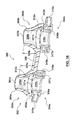
- FIG. 8 is a perspective view of a nasal interface apparatus that depicts the nasal interface device of FIG. 1 connected to tubing for fluidly coupling to a respiratory assist device (not shown) and a pressurized respiratory gas source (not shown).
- FIG. 9 is a frontal view depiction of the nasal interface apparatus as shown in FIG. 8 being worn by a patient.
- FIG. 10 is a side view depiction of the nasal interface apparatus as shown in FIG. 8 being worn by a patient.
- FIG. 10A is a sectional view of a portion of the nasal interface apparatus within a patient's nostril as shown in FIG. 10 taken along line A-A thereof.
- FIG. 10B is the sectional view of the portion of the nasal interface apparatus shown in FIG. 10A depicting the delivery of a respiratory gas during an inspiratory effort of the patient.
- FIG. 10C is the sectional view of the portion of the nasal interface apparatus shown in FIG. 10A depicting an expiratory effort of the patient.
- FIG. 11 is a perspective bottom view of a nasal interface device in accordance with another embodiment hereof.
- FIG. 11A is a sectional view of a portion of the nasal interface apparatus shown in FIG. 11 within a patient's nostril.
- FIG. 12 is an exploded perspective view of the nasal interface device of FIG. 11 showing various subcomponents thereof.
- FIG. 13 is a top view of a portion of the nasal interface device of FIG. 11 .
- FIG. 14 is a partial sectional view of the portion of the nasal interface shown in FIG. 13 taken along line A-A thereof.
- FIG. 15 is a perspective bottom view of the portion of the nasal interface shown in FIG. 13 .
- FIG. 16 is a sectional view of a nasal interface device in accordance with another embodiment hereof.
- FIG. 16A is a sectional view of a portion of the nasal interface apparatus of FIG. 16 positioned within a patient's nostril.
- FIGS. 17 and 18 are exploded perspective views of the nasal interface device of FIG. 16 showing various subcomponents thereof.
- FIGS. 19 and 20 are schematic depictions of ambulatory assist ventilation (AAV) systems in accordance with embodiments hereof.
- AAV ambulatory assist ventilation
- FIG. 21 is a schematic depiction of multiple pneumatically common sensing ports in accordance with embodiment hereof.
- FIG. 22 is an exploded perspective view of a nasal interface device in accordance with another embodiment hereof showing various subcomponents thereof.
- FIG. 23 is a top view of the nasal interface device of FIG. 22 .
- FIGS. 24 and 25 are exploded perspective views of a nasal interface device in accordance with another embodiment hereof showing various subcomponents thereof.
- FIG. 26 is a top view of the nasal interface device of FIGS. 24 and 25 .
- FIG. 27 is a perspective bottom view of the nasal interface device of FIGS. 24 and 25 .
- FIGS. 28 and 29 are exploded perspective views of a nasal interface device in accordance with another embodiment hereof showing various subcomponents thereof.
- FIG. 30 is a top view of the nasal interface device of FIGS. 28 and 29 .
- FIG. 31 is a perspective bottom view of the nasal interface device of FIGS. 28 and 29 .
- proximal and distal are used in the following description with respect to a position or direction relative to the respiratory assist device.
- Proximal and proximally are a position near from or in a direction toward the respiratory assist device.
- distal or disally are a position distant or in a direction away from the respiratory assist device.
- FIGS. 1-7 depict various views of a nasal interface device 100 in accordance with an embodiment hereof.
- FIGS. 1, 2 and 3 are side, end and top views, respectively, of nasal interface 100 with FIGS. 4 and 5 being exploded perspective views of nasal interface 100 that show the various components thereof.
- FIG. 6 is a perspective bottom view of nasal interface 100
- FIG. 7 is a sectional view of nasal interface 100 taken along line A-A of FIG. 3 .
- Nasal interface 100 is used with a respiratory assist device that doses compressed respiratory gas from a compressed respiratory gas source, as will be described in more detail below.
- nasal interface 100 is configured to be worn by a user to deliver a mixture of respiratory gas and entrained ambient air during an inspiratory effort of the patient and to permit exhalation therethrough during an expiratory effort of the patient, which will also be described in more detail below.
- Nasal interface 100 includes a nasal pillow component 102 and a pair of hub components 104 a , 104 b .
- Nasal pillow component 102 includes nasal pillows 102 a , 102 b that are tubular structures with proximal or first ends 103 a , 103 b and distal or second ends 105 a , 105 b .
- a central passageway 126 a , 126 b is defined by tubular body portions 125 a , 125 b of each nasal pillow 102 a , 102 b from substantially a first end 103 a , 103 b to a respective second end 105 a , 105 b thereof.
- tubular body portions 125 a , 125 b of nasal pillows 102 a , 102 b is configured to have an ergonomic oval cross-section along an entire length thereof and are intended to be inserted in their entirety into the nasal cavity to assist in anchoring nasal interface 100 within a user's nostrils.
- a connector strip 106 is a thin flexible segment of nasal pillow component 102 that extends between first ends 103 a , 103 b of nasal pillows 102 a , 102 b , respectively, to provide flexibility and articulation between nasal pillows 102 a , 102 b so as to permit adjustment to the particular anatomy of a user.
- connector strip 106 may be a sinusoidal strip, two or more, parallel strips, or a chain or series of oval or circular shapes that extend between nasal pillows 102 a , 102 b , respectively.
- nasal pillow component 102 with nasal pillows 102 a , 102 b and connector strip 106 is a molded component of an elastomeric material, such as 30 Shore A silicone.
- the pillows do not require or include a “bulge” or shock absorber section that are typically found in the art to permit the pillows to articulate and compress to fit and seal against the anatomy of a user because the connector strip 106 , allows the nasal pillow components to independently articulate in order for them to fit entirely into the user's nostrils creating an airtight seal.
- Hub components 104 a , 104 b are concentrically disposed with first ends 103 a , 103 b of nasal pillows 102 a , 102 b , respectively.
- each hub component 104 a , 104 b includes a distal support structure 108 a , 108 b , a central hub 110 a , 110 b with a plurality of delivery openings 112 a , 112 b , and a proximal plenum structure 114 a , 114 b .
- each hub component 104 a , 104 b are periodically spaced about a perimeter of a distal face 121 a , 121 b of respective central hub 110 a , 110 b .
- each delivery opening 112 a , 112 b has a substantially circular cross-section.
- Proximal plenum structures 114 a , 114 b in conjunction with central hub 110 a , 110 b form an enclosed space or plenum in which the air pressure is elevated above ambient pressure.
- Distal support structures 108 a , 108 b include annular rims 109 a , 109 b and spokes or struts 111 a , 111 b that radially extend between annular rims 109 a , 109 b and respective central hubs 110 a , 110 b .
- spokes or struts 111 a , 111 b that radially extend between annular rims 109 a , 109 b and respective central hubs 110 a , 110 b .
- spokes 111 a , 111 b more or fewer spokes may be used in support structures 108 a , 108 b in accordance with various embodiments hereof.
- each support structure 108 a , 108 b and its respective central hub 110 a , 110 b is a single molded component of a polycarbonate.
- a series of ambient air apertures 116 a , 116 b are formed between respective annular rims 109 a , 109 b , adjacent spokes 111 a , 111 b and central hubs 110 a , 110 b , such that as shown in FIGS. 6 and 7 , the series of ambient air apertures 116 a , 116 b of nasal interface 100 are disposed proximate first ends 103 a , 103 b of each nasal pillow 102 a , 102 b , respectively, to substantially surround the respective central hub 110 a , 110 b disposed therein.
- Central hubs 110 a , 110 b of hub components 104 a , 104 b are positioned to be coaxial with respective distal ports 101 a , 101 b of nasal pillows 102 a , 102 b such that the plurality of delivery openings 112 a , 112 b of each hub are positioned to deliver a respiratory gas within its respective nasal pillow.
- Proximal plenum structures 114 a , 114 b of hub components 104 a , 104 b define an inlet 115 a , 115 b for receiving a respiratory gas from the respiratory assist device (not shown) and a plenum or chamber 117 a , 117 b for distributing the respiratory gas to the plurality of delivery openings 112 a , 112 b of respective central hubs 110 a , 110 b .
- Proximal plenum structures 114 a , 114 b include distally extending annular flanges 118 a , 118 b that snap, or are otherwise secured by ultrasonically welding or gluing, within corresponding proximal recesses 120 a , 120 b within central hubs 110 a , 110 b .
- plenum structures 114 a , 114 b are molded components of a polycarbonate or acrylonitrile butadiene styrene (ABS).
- Hub components 104 a , 104 b further include outlet discs 122 a , 122 b having a plurality of outlets or holes 119 a , 119 b and seals 124 a , 124 b .
- outlet discs 122 a , 122 b are formed from a thin sheet of a metal, such as stainless steel or brass, with outlets 119 a , 119 b formed therethrough by electrochemical etching.
- outlet discs 122 a , 122 b have a thickness or depth of less than 0.040 inch with each outlet 119 a , 119 b having a diameter of less than 0.010 inch.
- outlet discs 122 a , 122 b have a thickness or depth that is less than a diameter of each outlet 119 a , 119 b , e.g., an outlet disc thickness or depth of 0.005 inch and an outlet diameter of 0.010 inch.
- the plurality of outlets 119 a , 119 b of outlet discs 122 a , 122 b correspond in number and orientation to the plurality of delivery openings 112 a , 112 b of respective central hubs 110 a , 110 b .
- each of the delivery openings 112 a , 112 b has a diameter that is slightly greater than the diameter of a corresponding disc outlet with each delivery opening 112 a , 112 b being sized to be large enough to not impede on the flow exiting from a corresponding disc outlet 119 a , 119 b .
- Outlet discs 122 a , 122 b and seals 124 a , 124 b are disposed within proximal recesses 120 a , 120 b of central hubs 110 a , 110 b such that disc outlets 119 a , 119 b substantially align with corresponding central hub delivery openings 112 a , 112 b .
- each disc outlet 119 a , 119 b i.e., diameter and depth, and respective larger hub delivery opening 112 a , 112 b provides for a softer more diffusive gas flow to the patient such that the patient is less likely to experience discomfort due to flow impingement, most particularly if the disc outlet thickness or depth is less than a diameter of the disc outlet.
- outlet discs 122 a , 122 b and central hubs 110 a , 110 b are oval.
- outlet discs 122 a , 122 b are held or pressed against respective proximal faces 132 a , 132 b of central hubs 110 a , 110 b by respective annular flanges 118 a , 118 b of proximal plenum structures 114 a , 114 b with seals 124 a , 124 b therebetween.
- Hub components 104 a , 104 b are attached to nasal pillow component 102 by respective annular rims 109 a , 109 b , each of which in the embodiment shown in FIGS. 4 and 5 includes a series of post-forming apertures 107 a , 107 b that receive a material of nasal pillow component 102 there through in an over-molding process that is used to connect the structures together, as best seen in the sectional view of nasal interface 100 shown in FIG. 7 .
- nasal pillow component 102 may be glued or otherwise attached to annular rims 109 a , 109 b of hub components 104 a , 104 b.
- a pattern of the plurality of disc outlets 119 a , 119 b and delivery openings 112 a , 112 b of central hubs 110 a , 110 b , respectively, are shaped and positioned to correspond with the respective distal port 101 a , 101 b of nasal pillows 102 a , 102 b so that the flow of a respiratory gas from the plurality of disc outlets 119 a , 119 b and delivery openings 112 a , 112 b in conjunction with ambient air that is entrained by the respiratory gas flow from ambient air apertures 116 a , 116 b substantially fills the respective proximal port 101 a , 101 b prior to entering a respective nare of the patient, which will be explained in more detail below with reference to FIGS.
- the plurality of disc outlets 119 a , 119 b and delivery openings 112 a , 112 b are in a pattern that corresponds to a shape of the respective proximal port 101 a , 101 b of nasal pillows 102 a , 102 b .
- the plurality of disc outlets 119 a , 119 b and delivery openings 112 a , 112 b may be arranged to form, for example, a circular, polygonal or cross pattern or a series of parallel lines through a respective central hub 110 a , 110 b that is configured such that the respective nasal pillow proximal port 101 a , 101 b is filled with the respiratory gas/ambient air outflow stream that is created thereby.
- an outlet disc may be omitted with the plurality of delivery openings of the central hubs being sized and configured to produce/deliver the pressurized respiratory gas/entrained air outflow stream to the respective nasal pillow proximal ports.
- FIG. 8 is a perspective view of a nasal interface apparatus 130 that includes nasal interface 100 connected to tubing or tubes 128 a , 128 b for fluidly coupling the nasal interface to a respiratory assist device (not shown) and a pressurized respiratory gas source (not shown), with FIGS. 9 and 10 being frontal and side views, respectively, depicting nasal interface apparatus 130 being worn by a patient.
- the unencumbering, low profile of nasal interface 100 is clearly depicted in FIGS.
- nasal interface apparatus 130 adds to the overall unencumbering nature of nasal interface apparatus 130 , which may help to reduce the self-consciousness of a wearer, to reduce impediment while eating and drinking, and/or to reduce interference with eye wear and facial hair, such as mustaches.
- Tubing 128 a , 128 b includes a first inner diameter from first or distal ends 127 a , 127 b , where each of tubing 128 a , 128 b connects with the respective hub component inlet 115 a , 115 b , to flared or stepped-up segments 129 a , 129 b of tubing 128 a , 128 b that are disposed along a length of the respective tubing that is intended to sit behind or under a patient's ear.
- Tubing 128 a , 128 b includes a second inner diameter that is greater than the first inner diameter from flared or stepped-up segments 129 a , 129 b to second or proximal ends 131 a , 131 b.
- a first inner diameter of tubing 128 a , 128 b may be in the range of 0.020 inch to 0.070 inch and a second inner diameter of tubing 128 a , 128 b may be in the range of 0.080 inch to 0.125 inch.
- the smaller first inner diameter tubing increases in diameter at flared or stepped-up segments 129 a , 129 b behind the patient's ear and thereby minimizes pressure drop compared to having the smaller first inner diameter tubing extend to the respiratory assist device or a Y- or T-connector.
- Second ends 131 a , 131 b of tubing 128 a , 128 b may each directly connect to the respiratory assist device, as depicted in the system of FIG. 19 , or may connect via a T- or Y-connector to another length of tubing or hose that connects with the respiratory assist device, as depicted in the system of FIG. 20 .
- each tubing 128 a , 128 b may be formed from more than one segment of tubing or tubes with at least a first or proximal segment of tubing having the first inner diameter and a second or distal segment of tubing having the second inner diameter with flared or stepped-up segment 129 a , 129 b being a flared connector, fitting or additional segment of tubing that fluidly couples the first and second segments of tubing together while providing a gradual transition between the first and second inner diameters thereof.
- tubing 128 a , 128 b may have more than one flared or stepped-up segment between the first and second ends thereof.
- FIG. 10A is a simplified sectional view taken along line A-A in FIG. 10 of a patient's nostril PN with a portion of nasal interface 100 disposed therein.
- a length L 1 of tubular body portion 125 a of nasal pillow 102 a is greater than a length L 2 of hub component 104 a , with the length L 1 of the nasal pillow body portion being sized to fit within the nostril of a user and with a length L 3 being a length of hub component 104 a that extends slightly proximal of the nostril opening.
- a length L 1 of tubular body portion 125 a may be in the range of 0.10 inch to 0.60 inch
- a length L 2 of hub component 104 a may be in the range of 0.05 inch to 0.40 inch
- a length L 3 being a length of hub component 104 a that extends slightly proximal of the nostril opening may be in the range of 0.050 inch to 0.30 inch.
- a width of nasal pillow 102 a at the half line, L 1 ′/2 is equivalent to a width of the nostril opening and/or a width of hub component 104 a is selected to be no wider than a rim of the nostril opening.
- a length L 1 of tubular body portion 125 a of nasal pillow 102 a is sized to reside within the nostril of a user such that when nasal interface 100 is worn by the user connector strip 106 abuts against the columella C between the patient's nostrils while the remainder of the nasal interface 100 , which includes length L 3 of hub component 104 a , is disposed within or slightly proximal of the nostril of the user, as depicted in FIGS. 9, 10 and 10A .
- an overall length L 1 ′ of nasal pillow 102 a is sized such that when nasal interface 100 is worn by a user the nasal pillow first end 103 a does not substantially extend beyond the nostril opening of the user.
- an overall length L 1 ′ of nasal pillows 102 a , 102 b may be in the range of 0.10 inch to 0.60 inch.
- the use of the phrase “does not substantially extend beyond the nostril opening of a user” is meant to convey that none of to less than a quarter of a length of the nasal pillow extends below or proximal of the rim of the nostril opening.
- FIGS. 10B and 10C are sectional views taken along line A-A in FIG. 10 of a portion of nasal interface 100 , with FIG. 10B depicting the delivery of respiratory gas and entrained ambient air during an inspiratory effort of the patient and FIG. 10C depicting an expiratory effort of the patient.
- Central hub 110 a of hub component 104 a is positioned at first or proximal end 103 a of nasal pillow 102 a so as to be substantially coaxial with distal port 101 a of the nasal pillow.
- the flow of a pressurized respiratory gas from the plurality of delivery openings 112 a of central hub 110 a (represented by arrows made with dot-dashed lines in FIG.
- the size of ambient air apertures 116 a , 116 b and their position within nasal interface 100 to be substantially aligned with rims of the patient's nostril provides less resistance to the patient's inhalation and exhalation and particularly minimizes exhalation resistance, such that the nasal interface does not interfere with the patient's breathing out to thereby prevent undesirable “breath stacking.”
- the arrangement and number of disc outlets 119 a , 119 b or delivery openings 112 a of central hub 110 a and their location proximate to or near the ambient air apertures 116 a provides 300% to 400% of ambient air entrainment, which conserves the respiratory gas supply while providing a therapeutic volume of the entrained ambient air and respiratory gas mixture to the patient.
- the arrangement and number of disc outlets 119 a , 119 b or delivery openings 112 a of central hub 110 a and their location within the nasal interface proximate to or near the ambient air apertures 116 a provides a therapeutic volume of an entrained ambient air and respiratory gas mixture to the patient that has 3 to 5 times more entrained ambient air than respiratory gas, which also serves to conserve the respiratory gas supply.
- the afore-mentioned improvement in entrainment is realized due to the arrangement of disc outlets or delivery openings, the number of pressurized respiratory gas disc outlets or delivery openings, the minimal diameters of each disc outlet or delivery opening and the spacing, nearness and/or proximity of the disc outlet or delivery openings to the ambient air aperture(s).
- the arrangement of delivery openings is preferably configured in a pattern that will maximize the amount of respiratory gas flow from each of the delivery openings that is exposed to entrained ambient air while also maximizing a size of the ambient air aperture so as to permit a maximum amount of entrained ambient air to flow through and into the nasal pillows of the nasal interface. Furthermore, it is preferable to maximize the number of delivery openings, while maintaining a constant net sum of the cross-sectional areas of the openings, i.e., minimal diameters, which further increases the perimetrical amount of respiratory gas flow from each of the delivery openings that is exposed to the entrained ambient air while minimizing an internal area of the respiratory gas flow that is not exposed to the entrained ambient air. Additionally, it is preferred to locate the delivery openings in close proximity to the ambient air aperture(s) to maximize exposure of the respiratory gas flow from each delivery opening with the entrained ambient air.
- the number of pressurized respiratory gas disc outlets or delivery openings, the minimal diameters of each disc outlet or delivery opening and the spacing, nearness and/or proximity of the disc outlets or delivery openings to the ambient air aperture(s) also permits the delivery of the pressurized respiratory gas relatively close to or near the entrance to the nare opening without creating discomfort to the patient due to flow impingement, and it is consideration of these factors that has led to the development of the small, lightweight and discrete nasal interfaces of embodiments hereof.
- the amount of fluid power exiting each discrete disc outlet or delivery opening is proportional to the mass flow rate and the square of the velocity. By design to increase entrainment and patient pressure, the fluid velocity out of each outlet or opening is sonic.
- Sonic flow is a physical limitation of the fluid speed exiting an outlet or opening.
- the mass flow rate exiting each disc outlet/delivery opening is reduced by the total amount of outlets/openings, assuming a constant net sum of the cross-sectional areas of the openings. Therefore, for e.g., when ten outlets are to be employed as opposed to one outlet, the fluid power out of each opening would be 1/10 that of a single outlet. This will reduce the discomfort transmitted to the patient do to flow impingement.
- distal surfaces 121 a , 121 b of central hubs 110 a , 110 b of hub components 104 a , 104 b include the plurality of delivery openings 112 a , 112 b formed therein with outlet discs 122 a , 122 b secured therein.
- distal surfaces 121 a , 121 b of each central hub 110 a , 110 b may be one of aligned with, proximal to and distal of a proximal surface 123 of nasal pillow component 102 .
- FIG. 11 is a perspective bottom view of a nasal interface device 200 in accordance with another embodiment hereof, with FIG. 12 being an exploded perspective view of nasal interface device 200 showing various subcomponents thereof.
- the embodiment of FIGS. 11-15 may be used with all features described with reference to other embodiments hereof and only features and functions that differ from those already described will be detailed herein.
- Nasal interface 200 includes a nasal pillow component 202 and a pair of hub components 204 a , 204 b .
- Nasal pillow component 202 includes nasal pillows 202 a , 202 b with tubular body portions 225 a , 225 b having lattice-like walls that include a series of circumferentially extending apertures 233 a , 233 b therethrough.
- nasal pillows 202 a , 202 b aids in anchoring the nasal pillow within a respective nare of the nasal interface wearer, while improving comfort of the wearer.
- Nasal pillows 202 a , 202 b have proximal or first ends 203 a , 203 b and distal or second ends 205 a , 205 b .
- a central passageway 226 a , 226 b is defined by tubular body portions 225 a , 225 b of each nasal pillow 202 a , 202 b from substantially a first end 203 a , 203 b to a respective second end 205 a , 205 b thereof.
- Nasal pillow component 202 also includes distal support structures 208 a , 208 b for attaching nasal pillow component 202 to hub components 204 a , 204 b , as described below.
- a connector strip 206 is a thin flexible segment of nasal pillow component 202 that extends between struts 211 a , 211 b proximal of first ends 203 a , 203 b of nasal pillows 202 a , 202 b , respectively, to provide flexibility and articulation between nasal pillows 202 a , 202 b so as to permit adjustment to the particular anatomy of a user.
- nasal pillow component 202 with nasal pillows 202 a , 202 b , connector strip 206 and distal support structures 208 a , 208 b is a unitary, contiguous molded component.
- nasal pillow component 202 is of an elastomeric material, such as 30 Shore A silicone.
- Nasal pillows 202 a , 202 b are formed to have concave outer surfaces distal of first ends 203 a , 203 b that form grooves 235 a , 235 b for accommodating and/or contouring to a respective rim or lip of the nostril opening. As best shown in FIG.
- distal support structures 208 a , 208 b include sealing rings 224 a , 224 b and struts or members 211 a , 211 b with each strut 211 a , 211 b laterally or radially extending between a respective sealing ring 224 a , 224 b and a respective first end 203 a , 203 b of a respective nasal pillow 202 a , 202 b .
- more or fewer struts may be used in support structures 208 a , 208 b in accordance with various embodiments hereof.
- Struts 211 a , 211 b are configured to permit a change in an aspect ratio of a cross-section of respective nasal pillows 202 a , 202 b from which they extend, which permits the respective nasal pillow to be squeezed radially inward or otherwise elastically deformed for insertion within a nostril and when released substantially return to their original shape to thereby anchor within a respective nostril to secure nasal interface 200 to the patient.
- nasal interface 200 provides for a more comfortable and secure fit for the user.
- the aspect ratio of the cross-section is the ratio of the larger diameter of the major axis of the ellipse to the smaller diameter of the minor axis of the ellipse.
- the flexibility of struts 211 a , 211 b permits the change in the aspect ratio of the cross-section of the respective nasal pillow 202 a , 202 b .
- a shape of struts 211 a , 211 b permits the change in the aspect ratio of the cross-section of the respective nasal pillow 202 a , 202 b , such as the curved, thin and narrow strip-like or plank-like shape of struts 211 a , 211 b .
- strut 211 a , 211 b may have a shape of a curved beam with a circular or square cross-section that permits the change in the aspect ratio of the cross-section of the respective nasal pillow 202 a , 202 b.
- Hub components 204 a , 204 b include central hubs 210 a , 210 b having distal surfaces 221 a , 221 b through which a plurality of delivery openings 212 a , 212 b are formed and a proximal plenum structure 214 a , 214 b that defines an inlet 215 a , 215 b for receiving a compressed or pressurized respiratory gas and a plenum 217 a , 217 b for distributing the respiratory gas through the plurality of delivery openings 212 a , 212 b .
- Hub components 204 a , 204 b are attached to nasal pillow component 202 so as to be concentrically or axially disposed with respective distal ports 201 a , 201 b of nasal pillows 202 a , 202 b such that the plurality of delivery openings 212 a , 212 b of each central hub 210 a , 210 b are sized and positioned to deliver a respiratory gas within its respective nasal pillow.
- distal surfaces 221 a , 221 b of central hubs 210 a , 210 b have a thickness or depth of less than 0.040 inch with each delivery opening 212 a , 212 b having a diameter of less than 0.010 inch.
- each of the plurality of delivery openings 212 a , 212 b forms a pattern in the distal surface of its respective central hub that corresponds to a shape of the corresponding distal port 201 a , 201 b .
- hub components 204 a , 204 b are attached to nasal pillow component 202 by positioning a respective sealing ring 224 a , 224 b between its corresponding central hub 210 a , 210 b and proximal plenum structure 214 a , 214 b , and securing the respective central hub 210 a , 210 b and proximal plenum structure 214 a , 214 b together with the respective sealing ring 224 a , 224 b sandwiched therebetween.
- each proximal plenum structure 214 a , 214 b is attached to its respective central hub 210 a , 210 b by any suitable means known to one of skill in the art, such as by a snap fit, gluing or welding.
- outlet discs similar to outlet discs 122 a , 122 b may be used with central hubs 210 a , 210 b with the disc outlets being sized and configured to produce/deliver the pressurized respiratory gas/entrained air outflow stream to the respective nasal pillow proximal ports 201 a , 201 b .
- each of the plurality of delivery openings 212 a , 212 b would be adapted to have a diameter that is slightly greater than the diameter of a corresponding disc outlet such that each delivery opening 212 a , 212 b is large enough to not impede on the flow exiting from a corresponding disc outlet or outlets.
- a series of ambient air apertures 216 a , 216 b are formed between respective portions of annular first ends 203 a , 203 b of nasal pillows 202 a , 202 b , adjacent struts 211 a , 211 b and central hubs 210 a , 210 b such that as shown in FIGS. 11, and 13-15 , the series of ambient air apertures 216 a , 216 b of nasal interface 200 are disposed proximate to or near first ends 203 a , 203 b of each nasal pillow 202 a , 202 b , respectively, to substantially surround the respective hub components 204 a , 204 b disposed therein.
- Nasal interface device 200 is fluidly connectable to a respiratory assist device via tubing for receiving the respiratory gas therefrom, as described above with reference to FIG. 8 that depicts nasal interface apparatus 130 .
- Nasal interface device 200 also functions in a similar manner as described above with reference to the previous embodiment. More particularly with reference to FIG.
- FIG. 11A which is a sectional view of a portion of nasal interface apparatus 200 within a patient's nostril, during an inspiratory phase of a patient wearing nasal interface device 200 as part of apparatus 130 , the flow of a pressurized respiratory gas from the plurality of delivery openings 212 b of central hub 210 b in conjunction with entrained ambient air drawn from ambient air apertures 216 b produces an outflow stream that substantially fills proximal port 201 b prior to exiting nasal pillow 202 b and entering a respective nare of the patient.
- an overall length L 1 ′ of each nasal pillow 202 a , 202 b is the same as a length L 1 of its tubular body portion 225 a , 225 b and is sized such that when nasal interface 200 is worn by a user the nasal pillow first end 203 a , 203 b does not extend beyond the nostril opening of the user with a rim or lip of the nostril opening fitting or abutting against a respective groove 235 a , 235 b of the nasal pillow 202 a , 202 b .
- length L 1 , L 1 ′ of tubular body portion 225 b /nasal pillow 202 b is greater than a length L 2 of hub component 204 b , with length L 1 , L 1 ′ of tubular body portion 225 b /nasal pillow 202 b being sized to fit within the nostril of a user.
- a length L 1 of tubular body portions 225 a , 225 b may be in the range of 0.10 inch to 0.60 inch and a length L 2 of hub components 204 a , 204 b may be in the range of 0.05 inch to 0.40 inch.
- FIG. 16 is a sectional view of a nasal interface device 300 in accordance with another embodiment hereof, with FIGS. 17 and 18 being exploded perspective views showing various subcomponents of nasal interface device 300 .
- the embodiment of FIGS. 16-18 may be used with all features described with reference to other embodiments hereof and only features and functions that differ from those already described will be detailed herein.
- Nasal interface 300 includes a nasal pillow component 302 and a pair of annular hub components 304 a , 304 b .
- Annular as used to describe various features of embodiments hereof means substantially shaped like a ring, hollow cylinder, or toroid and is not meant to be limited to a such shapes having a circular perimeter but is intended to include various other perimetrical shapes such as oval, elliptical, etc.
- Nasal pillow component 302 includes nasal pillows 302 a , 302 b with tubular body portions 325 a , 325 b defining central passageways 326 a , 326 b from substantially first or proximal ends 303 a , 303 b to respective second ends 305 a , 305 b thereof.
- Nasal pillow component 302 also includes a connector strip 306 that extends between nasal pillow first ends 303 a , 303 b to provide flexibility and articulation between nasal pillows 302 a , 302 b so as to permit adjustment to the particular anatomy of a user.
- nasal pillow component 302 with nasal pillows 302 a , 302 b and connector strip 306 is a molded component of an elastomeric material, such as 30 Shore A silicone.
- Annular hub components 304 a , 304 b are concentrically disposed with or at first ends 303 a , 303 b of nasal pillows 302 a , 302 b , respectively.
- each annular hub component 304 a , 304 b includes an annular hub 310 a , 310 b with a plurality of delivery openings 312 a , 312 b formed through distal surfaces 321 a , 321 b thereof, and a proximal annular cap 336 a , 336 b .
- the plurality of delivery openings 312 a , 312 b are periodically spaced about distal surfaces 321 a , 321 b so as to circumferentially surround centrally located ambient air apertures 316 a , 316 b .
- the plurality of delivery openings 312 a , 312 b are sized to produce/deliver the pressurized respiratory gas/entrained air outflow stream to the respective nasal pillow proximal ports 301 a , 301 b .
- each of the plurality of delivery openings 312 a , 312 b has a circular cross-section.
- Annular hubs 310 a , 310 b define respective inlets 315 a , 315 b for receiving a respiratory gas from a respiratory assist device (not shown), and in conjunction with respective annular caps 336 a , 336 b form an enclosed space or plenum 317 a , 317 b for distributing the respiratory gas to the plurality of delivery openings 312 a , 312 b of the annular hub component.
- Annular caps 336 a , 336 b include distally extending annular flanges 318 a , 318 b that snap, or are otherwise secured by gluing or welding, within corresponding recesses within annular hubs 310 a , 310 b.
- Annular hubs 310 a , 310 b of annular hub components 304 a , 304 b are positioned to be coaxial with respective distal ports 301 a , 301 b of nasal pillows 302 a , 302 b such that the plurality of delivery openings 312 a , 312 b of each annular hub component are positioned to deliver a respiratory gas within its respective nasal pillow.
- a central ambient air aperture 316 a , 316 b is formed by respective inner circumferential surfaces of annular hub components 304 a , 304 b so as to be disposed proximate to or near the plurality of delivery openings 312 a , 312 b of the respective annular hubs 310 a , 310 b at first ends 303 a , 303 b of nasal pillows 302 a , 302 b , respectively, as shown in FIG. 16 .
- outlet discs similar to outlet discs 122 a , 122 b may be used with central hubs 310 a , 310 b with the disc outlets being sized and configured to produce/deliver the pressurized respiratory gas/entrained air outflow stream to the respective nasal pillow proximal ports 301 a , 301 b .
- each of the plurality of delivery openings 312 a , 312 b would be adapted to have a diameter that is slightly greater than the diameter of a corresponding disc outlet such that each delivery opening 312 a , 312 b is large enough to not impede on the flow exiting from a corresponding disc outlet or outlets.
- Nasal interface device 300 is fluidly connectable to a respiratory assist device via tubing for receiving the respiratory gas therefrom, as described above with reference to FIG. 8 that depicts nasal interface apparatus 130 .
- Nasal interface device 300 also functions in a similar manner as described above with reference to nasal interface device 100 .
- the flow of a pressurized respiratory gas from the plurality of delivery openings 312 a , 312 b of annular hubs 310 a , 310 b in conjunction with entrained ambient air drawn from centrally located ambient air apertures 316 a , 316 b produces an outflow stream that substantially fills proximal ports 301 a , 301 b prior to exiting nasal pillows 302 a , 302 b and entering a respective nare of the patient.
- FIG. 16A is a sectional view of a portion of nasal interface apparatus 300 of FIG. 16 positioned within a patient's nostril.
- An overall length L 1 ′ of each nasal pillow 302 a , 302 b is the same as a length L 1 of its tubular body portion 325 a , 325 b and is sized such that when nasal interface 300 is worn by a user the nasal pillow first end 303 a , 303 b does not extend beyond the nostril of the user with a rim or lip of the nostril opening abutting against a respective first end 303 a , 303 b of the nasal pillow 302 a , 302 b .
- FIG. 16A is a sectional view of a portion of nasal interface apparatus 300 of FIG. 16 positioned within a patient's nostril.
- An overall length L 1 ′ of each nasal pillow 302 a , 302 b is the same as a length L 1 of its tubular body portion 325 a , 325
- length L 1 , L 1 ′ of tubular body portion 325 a /nasal pillow 302 a is greater than a length L 2 of annular hub component 304 a , with length L 1 , L 1 ′ of tubular body portion 325 a /nasal pillow 302 a being sized to fit within the nostril of a user.
- a length L 1 of tubular body portions 325 a , 325 b may be in the range of 0.10 inch to 0.60 inch and a length L 2 of hub components 304 a , 304 b may be in the range of 0.05 inch to 0.40 inch.
- a length L 1 of tubular body portion 325 a of nasal pillow 302 a is sized to reside within the nostril of a user such that when nasal interface 300 is worn by the user connector strip 306 abuts against the columella C between the patient's nostrils while the remainder of the nasal interface 300 , which includes annular hub component 304 a , is disposed within or slightly proximal of the nostril of the user, as depicted in FIG. 16A .
- slightly proximal of the nostril of the user is meant to convey that no part of the nasal pillow or hub component extends a distance proximal of the rim of the nostril opening that is sufficient to touch or interact with any tissue proximate or proximal of the rim of the nostril opening.
- FIGS. 19 and 20 are schematic depictions of ambulatory assist ventilation (AAV) systems 1950 , 2050 in accordance with embodiments hereof that may include any one of nasal interface devices 100 , 200 , 300 , 400 , 500 , 600 as described above and a respiratory assist device 1952 , 2052 .
- respiratory assist device 1952 , 2052 are designed to be small and lightweight compared to existing respiratory ventilators which permits the device to be ambulatory.
- Respiratory assist device 1952 , 2052 can either be worn by the user using a belt clip, shoulder strap or while residing in a pack such as a backpack or waist pack.
- Respiratory assist device 1952 , 2052 can also be attached to the user's oxygen source (gaseous cylinder) eliminating the burden to the user of carrying the device.
- oxygen source gaseous cylinder
- Common functionalities of AAV systems 1950 , 2050 will be described together herein.
- AAV systems 1950 , 2050 deliver mechanical ventilatory support or positive airway pressure to a patient, while permitting less encumbered movement so as to facilitate mobility of the patient and to allow activities of daily living.
- a negative pressure develops within the nasal pillows of the nasal interface that gets communicated through one or more sensing ports of the nasal interface to respiratory assist device 1952 , 2052 and more particularly to a trigger or pressure sensor 1954 , 2054 contained therein.
- a continuous fluid flow passageway extends via tubing 1928 between trigger sensor 1954 and a central passageway of only one nasal pillow, with tubing 1928 having a first or proximal end coupled to respiratory assist device 1952 and a second or distal end couple to an inlet of the corresponding hub component of the nasal pillow.
- a continuous fluid flow passageway extends via tubing 2028 between trigger sensor 2054 and central passageways of each of the pair of nasal pillows, with tubing 2028 having a first or proximal end coupled to respiratory assist device 2052 and a second or distal end coupled to a connector or fitting that couples to two tubes or length of tubing, such as tubing 128 a , 128 b shown in FIG. 8 , that are attached to respective inlets of the hub components of the pair of nasal pillows.
- Trigger sensor 1954 , 2054 are configured to sense a negative pressure associated with an inspiratory phase of breathing, even a slight negative pressure, and when the negative pressure is sensed at a trigger value, logic controllers 1956 , 2056 in response thereto open a control or solenoid valve 1958 , 2058 to permit compressed respiratory gas to flow from compressed respiratory gas cylinders or reservoirs 1960 , 2060 to pressure regulators 1964 , 2064 , which reduce the respiratory gas pressure, and then through respective flow orifice 1962 , 2062 of the respiratory assist device to the nasal interface.
- a control or solenoid valve 1958 , 2058 to permit compressed respiratory gas to flow from compressed respiratory gas cylinders or reservoirs 1960 , 2060 to pressure regulators 1964 , 2064 , which reduce the respiratory gas pressure, and then through respective flow orifice 1962 , 2062 of the respiratory assist device to the nasal interface.
- the compressed respiratory gas flows to nasal interface 100 , 200 , 300 through tubing 1928 , 1928 ′, which in embodiments in accordance herewith may be or include lengths of tubing 128 a , 128 b as described above.
- the compressed respiratory gas flows to nasal interface 100 , 200 , 300 through tubing 2028 and 128 a , 128 b .
- the logic controllers 1956 , 2056 are programmed to open control valves 1958 , 2058 for a percentage of an inspiratory period and then to turn-off or close the control valve 1956 , 2056 /flow orifice 1962 , 2062 until after exhalation. In this manner a patient or wearer of nasal interface 100 , 200 , 300 is able to freely exhale through the nasal interface, as described above.
- one or more of tubing 128 a , 128 b , 1928 , 2028 defines a single lumen that is used both to provide fluid communication between the one or more sensing ports or openings of a corresponding hub component(s) of the nasal interface and the trigger sensor or pressure sensor of the respiratory assist device, and to deliver the compressed respiratory gas from the flow orifice of the respiratory assist device to the corresponding hub component(s) of the nasal interface.
- Single lumen tubing may be effectively used for combined sensing and respiratory gas delivery functionalities in embodiments hereof due to the efficient delivery of the compressed respiratory gas that is possible with nasal interfaces made in accordance with embodiments hereof.
- the efficient delivery of the compressed respiratory gas allows the use of regulated pressure respiratory gas, such as a compressed respiratory gas of less than 20 PSI, that does not adversely affect the trigger/pressure sensor during delivery of the lower pressure respiratory gas to the nasal pillows, such that the trigger/pressure sensor retains its functionality to sense very low pressures associated with triggering the next delivery of the respiratory gas.
- regulated pressure respiratory gas such as a compressed respiratory gas of less than 20 PSI
- the use of a single lumen tube allows the reduction of the overall diameter of the tubing as compared to dual or multiple lumen tubing. This reduction in diameter allows further reduction in the interface size and the amount of ‘bulk’ that is strung across the users face.
- a single lumen tube reduces the complexity of the circuit assembly by simplifying bifurcation points as well as connections to the interface and the respiratory assist devices as compared to multiple lumen tubing.
- a sensing opening or openings of nasal interfaces 100 , 200 , 300 , 400 , 500 , 600 may be one or more of the delivery openings of one of the hub components of the nasal interface.
- sensing openings of a nasal interface 100 used with AAV device 1950 may be either the plurality of delivery openings 112 a of hub component 104 a , or alternatively may be the plurality of delivery openings 112 b of hub component 104 b depending upon which of the hub components 102 a , 102 b is connected via tubing 1928 to trigger/pressure sensor 1954 of respiratory assist device 1952 .
- a sensing opening or openings of nasal interfaces 100 , 200 , 300 , 400 , 500 , 600 may be one or more of the delivery openings of each of the hub components of the nasal interface.
- sensing openings of a nasal interface 100 used with AAV device 2050 may be the plurality of delivery openings 112 a of hub component 104 a and the plurality of delivery openings 112 b of hub component 104 b that are connected via tubing 128 a , 128 b and tubing 2028 to trigger/pressure sensor 2054 of respiratory assist device 2052 .
- FIG. 21 is a schematic depiction of multiple pneumatically common sensing ports in accordance with embodiment hereof.
- the pressure communicated to the trigger/pressure sensor of AAV systems 1952 , 2052 will be roughly equivalent to the average of the pressure measured at each discrete sensing port across that area or P sensor ⁇ ( P 1 +P 2 +P 3 + . . . +P n ) ⁇ n, with n being the total number of sensing ports.
- a preferred average pressure across a sensing area may be established, which will reduce or eliminate the effect of localized velocity pressures that may occur at a single sensing port location. More particularly in known systems, velocity pressure at a single sensing port location, depending on flow direction, can disadvantageously either increase or reduce the static pressure measurement and thereby may yield erroneous pressure measurements that can ultimately affect the AAV system's ability to match the spontaneous breathing pattern of the user resulting in the system undesirably triggering out of synch. Such situations are avoided in accordance with embodiments hereof that include multiple sensing ports or openings that have pneumatic commonality via a plenum as described herein.
- each sensing port or opening being small relative to the plenum volume
- multiple pneumatically common sensing ports in accordance with embodiments hereof will act as a low pass filter between the source pressure of the respiratory gas, a proximal patient pressure, and the trigger/pressure sensor.
- the low pass filter affect is created by and a function of the restriction of the orifices and the compliance of the plenum. If the restriction is increased, such as by reducing a size of the sensing opening, and/or the compliance of the plenum were to increase, such as by using a larger plenum, then the amount of filtering would increase.
- the low pass filtering affect is advantageous as it may improve the AAV systems synchrony with the patient by reducing false or missed triggers that may otherwise be caused by a higher frequency noise signal that occurs without the low pass filter affect.
- FIG. 22 is an exploded perspective view of a nasal interface device 400 in accordance with another embodiment hereof that shares features with nasal interface device 100 of FIGS. 1-7 , with FIG. 23 depicting a top view of nasal interface device 400 .
- the embodiment of FIGS. 22 and 23 may be used or adapted for use with all features described with reference to other embodiments hereof and only features and functions that differ from those already described will be detailed herein.
- Nasal interface 400 includes nasal pillow component 102 and a pair of hub components 404 a , 404 b .
- Each hub component 404 a , 404 b includes a distal support structure 408 a , 408 b , a central hub 410 a , 410 b with a plurality of delivery openings 412 a , 412 b , outlet discs 122 a , 122 b having a plurality of outlets 119 a , 119 b , seals 124 a , 124 b and proximal plenum structures 114 a , 114 b.
- Hub components 404 a , 404 b are attached to nasal pillow component 102 by respective annular rims 409 a , 409 b , each of which in the embodiment shown in FIGS. 22 and 23 includes a series of post-forming apertures 407 a , 407 b that receive a material of nasal pillow component 102 there through in an over-molding process that is used to connect the structures together.
- nasal pillow component 102 may be glued or otherwise attached to annular rims 409 a , 409 b of hub components 404 a , 404 b .
- a series of ambient air apertures 416 a , 416 b are formed between respective annular rims 409 a , 409 b , adjacent spokes 411 a , 411 b and central hubs 410 a , 410 b.
- each hub component 404 a , 404 b are spaced about a perimeter of distal face 421 a , 421 b of respective central hub 410 a , 410 b and are sized to be large enough to not impede on the flow exiting from two or more disc outlets 119 a , 119 b .
- the plurality of outlets 119 a , 119 b of outlet discs 122 a , 122 b do not directly correspond in number and arrangement to the plurality of delivery openings 412 a , 412 b of respective central hubs 410 a , 410 b .
- Outlet discs 122 a , 122 b and seals 124 a , 124 b are disposed within proximal recesses (not shown) of central hubs 410 a , 410 b such that the two or more disc outlets 119 a , 119 b substantially align with a corresponding central hub delivery opening 412 a , 412 b .
- outlet discs 122 a , 122 b are held or pressed against respective proximal faces (not shown) of central hubs 410 a , 410 b by respective annular flanges 118 a , 118 b of proximal plenum structures 114 a , 114 b with seals 124 a , 124 b therebetween.
- FIGS. 24 and 25 are exploded perspective views of a nasal interface device 500 in accordance with another embodiment hereof showing various subcomponents thereof, with FIG. 26 depicting a top view of nasal interface device 500 and FIG. 27 depicting a perspective bottom view of nasal interface device 500 .
- the embodiment of FIGS. 24-27 may be used or adapted for use with all features described with reference to other embodiments hereof and only features and functions that differ from those already described will be detailed herein.
- Nasal interface 500 includes nasal pillow component 102 and a pair of hub components 504 a , 504 b .
- Each hub component 504 a , 504 b includes a distal support structure 508 a , 508 b , an X- or cross-shaped central hub 510 a , 510 b with a plurality of delivery openings 512 a , 512 b , X- or cross-shaped outlet discs 522 a , 522 b having a plurality of outlets 519 a , 519 b , X- or cross-shaped seals 524 a , 524 b and X- or cross-shaped proximal plenum structures 514 a , 514 b.
- Respective annular rims 509 a , 509 b of hub components 504 a , 504 b are attached to nasal pillow component 502 by gluing, welding or the like, and in another embodiment may include a series of post-forming apertures for receiving a material of nasal pillow component 102 there through in an over-molding process.
- a series of ambient air apertures 516 a , 516 b are formed between respective annular rims 509 a , 509 b , and X- or cross-shaped central hubs 510 a , 510 b.
- Central hubs 510 a , 510 b of hub components 504 a , 504 b are positioned to longitudinally align with respective distal ports 101 a , 101 b of nasal pillows 102 a , 102 b such that the plurality of disc outlets 519 a , 519 b and delivery openings 512 a , 512 b of each hub are positioned to deliver a respiratory gas within its respective nasal pillow.
- Proximal plenum structures 514 a , 514 b of hub components 504 a , 504 b define an inlet 515 a , 515 b for receiving a respiratory gas from the respiratory assist device (not shown) and a plenum or chamber 517 a , 517 b for distributing the respiratory gas to the plurality of disc outlets 519 a , 519 b and delivery openings 512 a , 512 b of respective central hubs 510 a , 510 b .
- a respective plenum 517 a , 517 b is formed when a proximal plenum structure 514 a , 514 b is secured or otherwise attached to a corresponding central hub 510 a , 510 b to be defined by proximal recesses 520 a , 520 b therebetween.
- Proximal plenum structures 514 a , 514 b are shaped and sized to snap or fit within corresponding proximal recesses 520 a , 520 b within central hubs 510 a , 510 b , to be secured therein by ultrasonic welding, gluing or the like.
- each hub component 504 a , 504 b are periodically spaced along X- or cross-shaped distal face 521 a , 521 b of respective central hub 510 a , 510 b and are sized to be large enough to not impede on the flow exiting from a corresponding disc outlet 519 a , 519 b , as best shown in FIG. 26 .
- the plurality of outlets 519 a , 519 b of outlet discs 522 a , 522 b directly correspond in number and arrangement to the plurality of delivery openings 512 a , 512 b of respective central hubs 510 a , 510 b .
- Outlet discs 522 a , 522 b and seals 524 a , 524 b are disposed within proximal recesses 520 a , 520 b of central hubs 510 a , 510 b such that the disc outlets 519 a , 519 b substantially align with corresponding central hub delivery openings 512 a , 512 b .
- outlet discs 522 a , 522 b are held or pressed against respective proximal faces (not shown) of central hubs 510 a , 510 b by proximal plenum structures 514 a , 514 b being received within proximal recesses 520 a , 520 b to press seals 224 a , 224 b against an edge or perimeter of respective outlet discs 522 a , 522 b.
- FIGS. 28 and 29 are exploded perspective views of a nasal interface device 600 in accordance with another embodiment hereof showing various subcomponents thereof, with FIG. 30 depicting a top view of nasal interface device 600 and FIG. 31 depicting a perspective bottom view of nasal interface device 600 .
- the embodiment of FIGS. 28-31 may be used or adapted for use with all features described with reference to other embodiments hereof and only features and functions that differ from those already described will be detailed herein.
- Nasal interface 600 includes nasal pillow component 102 and a pair of hub components 604 a , 604 b .
- Each hub component 604 a , 604 b includes a distal support structure 608 a , 608 b , an Y-shaped central hub 610 a , 610 b with a plurality of delivery openings 612 a , 612 b , Y-shaped outlet discs 622 a , 622 b having a plurality of outlets 619 a , 619 b , Y-shaped seals 624 a , 624 b and Y-shaped proximal plenum structures 614 a , 614 b.
- Respective annular rims 609 a , 609 b of hub components 604 a , 604 b are attached to nasal pillow component 602 by gluing, welding or the like, and in another embodiment may include a series of post-forming apertures for receiving a material of nasal pillow component 102 there through in an over-molding process.
- a series of ambient air apertures 616 a , 616 b are formed between respective annular rims 609 a , 609 b , and Y-shaped central hubs 610 a , 610 b.
- Central hubs 610 a , 610 b of hub components 604 a , 604 b are positioned to longitudinally align with respective distal ports 101 a , 101 b of nasal pillows 102 a , 102 b such that the plurality of disc outlets 619 a , 619 b and delivery openings 612 a , 612 b of each hub are positioned to deliver a respiratory gas within its respective nasal pillow.
- Proximal plenum structures 614 a , 614 b of hub components 604 a , 604 b define an inlet 615 a , 615 b for receiving a respiratory gas from the respiratory assist device (not shown) and a plenum or chamber 617 a , 617 b for distributing the respiratory gas to the plurality of disc outlets 619 a , 619 b and delivery openings 612 a , 612 b of respective central hubs 610 a , 610 b .
- a respective plenum 617 a , 617 b is formed when a proximal plenum structure 614 a , 614 b is secured or otherwise attached to a corresponding central hub 610 a , 610 b to be defined by proximal recesses 620 a , 620 b therebetween.
- Proximal plenum structures 614 a , 614 b are shaped and sized to snap or fit within corresponding proximal recesses 620 a , 620 b within central hubs 610 a , 610 b , to be secured therein by ultrasonic welding, gluing or the like.
- each hub component 604 a , 604 b are periodically spaced along Y-shaped distal face 621 a , 621 b of respective central hub 610 a , 610 b and are sized to be large enough to not impede on the flow exiting from a corresponding disc outlet 619 a , 619 b , as best shown in FIG. 30 .
- FIGS. 30 illustrates that in the embodiment of FIGS.
- the plurality of outlets 619 a , 619 b of outlet discs 622 a , 622 b directly correspond in number and arrangement to the plurality of delivery openings 612 a , 612 b of respective central hubs 610 a , 610 b .
- Outlet discs 622 a , 622 b and seals 624 a , 624 b are disposed within proximal recesses 620 a , 620 b of central hubs 610 a , 610 b such that the disc outlets 619 a , 619 b substantially align with corresponding central hub delivery openings 612 a , 612 b .
- outlet discs 622 a , 622 b are held or pressed against respective proximal faces (not shown) of central hubs 610 a , 610 b by proximal plenum structures 614 a , 614 b being received within proximal recesses 620 a , 620 b to press seals 624 a , 624 b against an edge or perimeter of respective outlet discs 622 a , 622 b.
Abstract
Description
P sensor≈(P 1 +P 2 +P 3 + . . . +P n)÷n,
with n being the total number of sensing ports.
Claims (54)
Priority Applications (1)
| Application Number | Priority Date | Filing Date | Title |
|---|---|---|---|
| US14/427,986 US10384028B2 (en) | 2012-09-12 | 2013-08-27 | Nasal interface apparatus and systems for use with a respiratory assist device |
Applications Claiming Priority (3)
| Application Number | Priority Date | Filing Date | Title |
|---|---|---|---|
| US201261699969P | 2012-09-12 | 2012-09-12 | |
| PCT/US2013/056702 WO2014042862A1 (en) | 2012-09-12 | 2013-08-27 | Nasal interface apparatus and systems for use with a respiratory assist device |
| US14/427,986 US10384028B2 (en) | 2012-09-12 | 2013-08-27 | Nasal interface apparatus and systems for use with a respiratory assist device |
Related Parent Applications (1)
| Application Number | Title | Priority Date | Filing Date |
|---|---|---|---|
| PCT/US2013/056702 A-371-Of-International WO2014042862A1 (en) | 2012-09-12 | 2013-08-27 | Nasal interface apparatus and systems for use with a respiratory assist device |
Related Child Applications (1)
| Application Number | Title | Priority Date | Filing Date |
|---|---|---|---|
| US16/275,255 Continuation US11376387B2 (en) | 2012-09-12 | 2019-02-13 | Nasal interface apparatus and systems for use with a respiratory assist device |
Publications (2)
| Publication Number | Publication Date |
|---|---|
| US20150250973A1 US20150250973A1 (en) | 2015-09-10 |
| US10384028B2 true US10384028B2 (en) | 2019-08-20 |
Family
ID=50278603
Family Applications (2)
| Application Number | Title | Priority Date | Filing Date |
|---|---|---|---|
| US14/427,986 Active 2036-04-09 US10384028B2 (en) | 2012-09-12 | 2013-08-27 | Nasal interface apparatus and systems for use with a respiratory assist device |
| US16/275,255 Active 2034-11-13 US11376387B2 (en) | 2012-09-12 | 2019-02-13 | Nasal interface apparatus and systems for use with a respiratory assist device |
Family Applications After (1)
| Application Number | Title | Priority Date | Filing Date |
|---|---|---|---|
| US16/275,255 Active 2034-11-13 US11376387B2 (en) | 2012-09-12 | 2019-02-13 | Nasal interface apparatus and systems for use with a respiratory assist device |
Country Status (5)
| Country | Link |
|---|---|
| US (2) | US10384028B2 (en) |
| EP (1) | EP2895222B1 (en) |
| CN (1) | CN104780965B (en) |
| ES (1) | ES2716051T3 (en) |
| WO (1) | WO2014042862A1 (en) |
Cited By (6)
| Publication number | Priority date | Publication date | Assignee | Title |
|---|---|---|---|---|
| USD879947S1 (en) * | 2017-11-15 | 2020-03-31 | Innomed Healthscience, Inc. | Respiratory mask |
| USD880687S1 (en) * | 2017-11-15 | 2020-04-07 | Innomed Healthscience, Inc. | Respiratory mask |
| US10702669B2 (en) | 2005-02-09 | 2020-07-07 | Vbox, Incorporated | Removable cartridge for oxygen concentrator |
| US11607519B2 (en) | 2019-05-22 | 2023-03-21 | Breathe Technologies, Inc. | O2 concentrator with sieve bed bypass and control method thereof |
| US11642486B2 (en) | 2019-05-17 | 2023-05-09 | Breathe Technologies, Inc. | Portable oxygen concentrator retrofit system and method |
| US11904096B2 (en) | 2012-09-12 | 2024-02-20 | Inogen, Inc. | Nasal interface apparatus and systems for use with a respiratory assist device |
Families Citing this family (21)
| Publication number | Priority date | Publication date | Assignee | Title |
|---|---|---|---|---|
| US9451981B2 (en) * | 2009-11-14 | 2016-09-27 | Spiway Llc | Surgical tissue protection sheath |
| US10384028B2 (en) | 2012-09-12 | 2019-08-20 | Silverbow Development, Llc | Nasal interface apparatus and systems for use with a respiratory assist device |
| US9995645B2 (en) * | 2013-10-18 | 2018-06-12 | Silverbow Development, Llc | Techniques for determining patient airway pressure |
| US11607517B2 (en) | 2014-07-18 | 2023-03-21 | Inogen, Inc. | Conforming nasal pillow |
| WO2016157103A1 (en) * | 2015-03-31 | 2016-10-06 | Fisher & Paykel Healthcare Limited | Nasal cannula |
| EP3328474B1 (en) * | 2015-07-31 | 2020-12-09 | ASAP Breatheassist Pty Ltd | Nasal devices |
| US20170281918A1 (en) * | 2016-03-31 | 2017-10-05 | Erich Gross | Nasal Dilator |
| EP3246064A1 (en) * | 2016-05-16 | 2017-11-22 | L'air Liquide, Societe Anonyme Pour L'etude Et L'exploitation Des Procedes Georges Claude | Nasal cannula |
| USD876615S1 (en) * | 2017-05-01 | 2020-02-25 | Inogen, Inc. | Nasal interface for ventilation |
| USD849929S1 (en) * | 2017-11-15 | 2019-05-28 | Innomed Healthscience, Inc. | Respiratory mask |
| USD868240S1 (en) * | 2017-11-15 | 2019-11-26 | Innomed Healthscience, Inc. | Respiratory mask |
| USD849238S1 (en) * | 2017-11-15 | 2019-05-21 | Innomed Healthscience, Inc. | Respiratory mask |
| USD852948S1 (en) * | 2017-11-15 | 2019-07-02 | Innomed Healthscience, Inc. | Respiratory mask |
| USD863535S1 (en) * | 2017-11-15 | 2019-10-15 | Innomed Healthscience, Inc. | Respiratory mask |
| USD868238S1 (en) * | 2017-11-15 | 2019-11-26 | Innomed Healthscience, Inc. | Respiratory mask |
| USD863537S1 (en) * | 2017-11-15 | 2019-10-15 | Innomed Healthscience, Inc. | Respiratory mask |
| USD863536S1 (en) * | 2017-11-15 | 2019-10-15 | InnoMed Healthsciene, Inc. | Respiratory mask |
| US20210236753A1 (en) * | 2018-02-02 | 2021-08-05 | Nathan T. Prather | Wearable intranasal clip apparatus and method of use |
| EP3840808A1 (en) * | 2018-08-23 | 2021-06-30 | Koninklijke Philips N.V. | Nasal portion and patient interface device including same |
| CN113474031A (en) * | 2019-01-24 | 2021-10-01 | 艾诺格有限公司 | Nasal interface device and system for a respiratory assistance device |
| USD938014S1 (en) * | 2019-05-30 | 2021-12-07 | Inogen, Inc. | Cannula pillows of a nasal interface device |
Citations (16)
| Publication number | Priority date | Publication date | Assignee | Title |
|---|---|---|---|---|
| US20020029004A1 (en) | 1998-02-25 | 2002-03-07 | Respironics, Inc. | Patient monitor and method of using same |
| US20050241644A1 (en) | 2004-04-09 | 2005-11-03 | Resmed Limited | Nasal assembly |
| US20090044808A1 (en) | 2007-07-30 | 2009-02-19 | Resmed Limited | Patient interface |
| CN101405047A (en) | 2006-03-17 | 2009-04-08 | 伊诺苏色管理股份公司 | Device for introducing breathing gas directly in the nose of a user |
| CN101455871A (en) | 2007-07-30 | 2009-06-17 | 雷斯梅德有限公司 | Patient Interface |
| US20100043801A1 (en) | 2008-08-19 | 2010-02-25 | Jordan Halling | Minimally invasive nasal cannula |
| WO2010115166A1 (en) | 2009-04-02 | 2010-10-07 | Breathe Technologies, Inc. | Methods, systems and devices for non-invasive open ventilation with gas delivery nozzles in free space |
| WO2011029073A1 (en) | 2009-09-03 | 2011-03-10 | Breathe Technologies, Inc. | Methods, systems and devices for non-invasive ventilation including a non-sealing ventilation interface with a free space nozzle feature |
| WO2011029074A1 (en) | 2009-09-03 | 2011-03-10 | Breathe Technologies, Inc. | Methods, systems and devices for non-invasive ventilation including a non-sealing ventilation interface with an entrainment port and/or pressure feature |
| US20110240035A1 (en) | 2008-11-21 | 2011-10-06 | Bidibots Pty Ltd | Respiratory assistance device and system and method |
| US8136525B2 (en) * | 2004-12-24 | 2012-03-20 | Resmed Limited | Mask system |
| USD662200S1 (en) | 2009-01-16 | 2012-06-19 | Breathe Technologies, Inc. | Nasal interface |
| US20120204870A1 (en) | 2008-06-12 | 2012-08-16 | Mcauley Alastair Edwin | Breathing assistance apparatus |
| US9132250B2 (en) | 2009-09-03 | 2015-09-15 | Breathe Technologies, Inc. | Methods, systems and devices for non-invasive ventilation including a non-sealing ventilation interface with an entrainment port and/or pressure feature |
| US9730830B2 (en) * | 2011-09-29 | 2017-08-15 | Trudell Medical International | Nasal insert and cannula and methods for the use thereof |
| US9962512B2 (en) | 2009-04-02 | 2018-05-08 | Breathe Technologies, Inc. | Methods, systems and devices for non-invasive ventilation including a non-sealing ventilation interface with a free space nozzle feature |
Family Cites Families (16)
| Publication number | Priority date | Publication date | Assignee | Title |
|---|---|---|---|---|
| US7059328B2 (en) * | 2000-03-13 | 2006-06-13 | Innomed Technologies, Inc. | Ventilation interface for sleep apnea therapy |
| CN2798975Y (en) * | 2005-03-10 | 2006-07-26 | 李松林 | Respiration therapeutic device for nose |
| US7559327B2 (en) * | 2005-05-31 | 2009-07-14 | Respcare, Inc. | Ventilation interface |
| US8753435B2 (en) | 2006-04-03 | 2014-06-17 | Ric Investments, Llc | Portable oxygen concentrator |
| US20070272247A1 (en) * | 2006-04-25 | 2007-11-29 | Oridion Medical Ltd. | Oral nasal cannula |
| EP2051761B1 (en) * | 2006-08-04 | 2019-08-21 | ResMed Pty Ltd | Nasal prongs for mask system |
| CN101653632A (en) * | 2008-06-04 | 2010-02-24 | 雷斯梅德有限公司 | Patient interface systems |
| CN102159273B (en) * | 2008-08-25 | 2015-01-28 | 皇家飞利浦电子股份有限公司 | Respiratory patient interfaces |
| JP2012508074A (en) | 2008-11-10 | 2012-04-05 | チャート・シークワル・テクノロジーズ・インコーポレイテッド | Medical ventilator system and method using an oxygen concentrator |
| WO2010137493A1 (en) * | 2009-05-29 | 2010-12-02 | 日本エー・シー・ピー株式会社 | Gas mist inhaler |
| US8616207B2 (en) | 2010-09-07 | 2013-12-31 | Inova Labs, Inc. | Oxygen concentrator heat management system and method |
| WO2012063532A1 (en) * | 2010-11-12 | 2012-05-18 | アルプス電気株式会社 | Arrival angle calculation device |
| US8440004B2 (en) | 2010-12-30 | 2013-05-14 | Inogen, Inc. | Advanced portable oxygen concentrator |
| US9486602B2 (en) * | 2011-06-22 | 2016-11-08 | Breathe Technologies, Inc. | Ventilation mask with integrated piloted exhalation valve and method of ventilating a patient using the same |
| US10384028B2 (en) | 2012-09-12 | 2019-08-20 | Silverbow Development, Llc | Nasal interface apparatus and systems for use with a respiratory assist device |
| US10245406B2 (en) | 2015-03-24 | 2019-04-02 | Ventec Life Systems, Inc. | Ventilator with integrated oxygen production |
-
2013
- 2013-08-27 US US14/427,986 patent/US10384028B2/en active Active
- 2013-08-27 WO PCT/US2013/056702 patent/WO2014042862A1/en active Application Filing
- 2013-08-27 CN CN201380058857.2A patent/CN104780965B/en active Active
- 2013-08-27 EP EP13837336.0A patent/EP2895222B1/en active Active
- 2013-08-27 ES ES13837336T patent/ES2716051T3/en active Active
-
2019
- 2019-02-13 US US16/275,255 patent/US11376387B2/en active Active
Patent Citations (27)
| Publication number | Priority date | Publication date | Assignee | Title |
|---|---|---|---|---|
| US20020029004A1 (en) | 1998-02-25 | 2002-03-07 | Respironics, Inc. | Patient monitor and method of using same |
| US20050241644A1 (en) | 2004-04-09 | 2005-11-03 | Resmed Limited | Nasal assembly |
| US8136525B2 (en) * | 2004-12-24 | 2012-03-20 | Resmed Limited | Mask system |
| CN101405047A (en) | 2006-03-17 | 2009-04-08 | 伊诺苏色管理股份公司 | Device for introducing breathing gas directly in the nose of a user |
| US20090101154A1 (en) | 2006-03-17 | 2009-04-23 | Innosuisse Management Ag | Device For Delivering Respiratory Gas Directly Into The Nose Of A User |
| CN101455871A (en) | 2007-07-30 | 2009-06-17 | 雷斯梅德有限公司 | Patient Interface |
| US20090044808A1 (en) | 2007-07-30 | 2009-02-19 | Resmed Limited | Patient interface |
| US20120204870A1 (en) | 2008-06-12 | 2012-08-16 | Mcauley Alastair Edwin | Breathing assistance apparatus |
| US20100043801A1 (en) | 2008-08-19 | 2010-02-25 | Jordan Halling | Minimally invasive nasal cannula |
| US20110240035A1 (en) | 2008-11-21 | 2011-10-06 | Bidibots Pty Ltd | Respiratory assistance device and system and method |
| USD662200S1 (en) | 2009-01-16 | 2012-06-19 | Breathe Technologies, Inc. | Nasal interface |
| WO2010115168A1 (en) | 2009-04-02 | 2010-10-07 | Breathe Technologies, Inc. | Methods, systems and devices for non-invasive open ventilation with gas delivery nozzles within an outer tube |
| US9675774B2 (en) | 2009-04-02 | 2017-06-13 | Breathe Technologies, Inc. | Methods, systems and devices for non-invasive open ventilation with gas delivery nozzles in free space |
| US10232136B2 (en) | 2009-04-02 | 2019-03-19 | Breathe Technologies, Inc. | Methods, systems and devices for non-invasive open ventilation for treating airway obstructions |
| WO2010115170A2 (en) | 2009-04-02 | 2010-10-07 | Breathe Technologies, Inc. | Methods, systems and devices for non-invasive open ventilation for treating airway obstructions |
| US20100252037A1 (en) | 2009-04-02 | 2010-10-07 | Breathe Technologies, Inc. | Methods, systems and devices for non-invasive open ventilation with gas delivery nozzles within nasal pillows |
| WO2010115169A1 (en) | 2009-04-02 | 2010-10-07 | Breathe Technologies, Inc. | Methods, systems and devices for non-invasive open ventilation for providing ventilation support |
| WO2010115166A1 (en) | 2009-04-02 | 2010-10-07 | Breathe Technologies, Inc. | Methods, systems and devices for non-invasive open ventilation with gas delivery nozzles in free space |
| US10046133B2 (en) | 2009-04-02 | 2018-08-14 | Breathe Technologies, Inc. | Methods, systems and devices for non-invasive open ventilation for providing ventilation support |
| US9962512B2 (en) | 2009-04-02 | 2018-05-08 | Breathe Technologies, Inc. | Methods, systems and devices for non-invasive ventilation including a non-sealing ventilation interface with a free space nozzle feature |
| US9180270B2 (en) | 2009-04-02 | 2015-11-10 | Breathe Technologies, Inc. | Methods, systems and devices for non-invasive open ventilation with gas delivery nozzles within an outer tube |
| US9227034B2 (en) | 2009-04-02 | 2016-01-05 | Beathe Technologies, Inc. | Methods, systems and devices for non-invasive open ventilation for treating airway obstructions |
| WO2011029073A1 (en) | 2009-09-03 | 2011-03-10 | Breathe Technologies, Inc. | Methods, systems and devices for non-invasive ventilation including a non-sealing ventilation interface with a free space nozzle feature |
| US20150314098A1 (en) | 2009-09-03 | 2015-11-05 | Breathe Technologies, Inc. | Methods, systems and devices for non-invasive ventilation including a non-sealing ventilation interface with an entrainment port and/or pressure feature |
| US9132250B2 (en) | 2009-09-03 | 2015-09-15 | Breathe Technologies, Inc. | Methods, systems and devices for non-invasive ventilation including a non-sealing ventilation interface with an entrainment port and/or pressure feature |
| WO2011029074A1 (en) | 2009-09-03 | 2011-03-10 | Breathe Technologies, Inc. | Methods, systems and devices for non-invasive ventilation including a non-sealing ventilation interface with an entrainment port and/or pressure feature |
| US9730830B2 (en) * | 2011-09-29 | 2017-08-15 | Trudell Medical International | Nasal insert and cannula and methods for the use thereof |
Non-Patent Citations (2)
| Title |
|---|
| International Search Report Application No. PCT/US2013/056702, dated Jan. 16, 2014, 3 pages. |
| International search report for application No. PCT/US2013/056702, dated Jan. 16, 2014. |
Cited By (7)
| Publication number | Priority date | Publication date | Assignee | Title |
|---|---|---|---|---|
| US10702669B2 (en) | 2005-02-09 | 2020-07-07 | Vbox, Incorporated | Removable cartridge for oxygen concentrator |
| US11389614B2 (en) | 2005-02-09 | 2022-07-19 | Vbox, Incorporated | Removable cartridge for oxygen concentrator |
| US11904096B2 (en) | 2012-09-12 | 2024-02-20 | Inogen, Inc. | Nasal interface apparatus and systems for use with a respiratory assist device |
| USD879947S1 (en) * | 2017-11-15 | 2020-03-31 | Innomed Healthscience, Inc. | Respiratory mask |
| USD880687S1 (en) * | 2017-11-15 | 2020-04-07 | Innomed Healthscience, Inc. | Respiratory mask |
| US11642486B2 (en) | 2019-05-17 | 2023-05-09 | Breathe Technologies, Inc. | Portable oxygen concentrator retrofit system and method |
| US11607519B2 (en) | 2019-05-22 | 2023-03-21 | Breathe Technologies, Inc. | O2 concentrator with sieve bed bypass and control method thereof |
Also Published As
| Publication number | Publication date |
|---|---|
| EP2895222B1 (en) | 2018-12-19 |
| EP2895222A1 (en) | 2015-07-22 |
| US20150250973A1 (en) | 2015-09-10 |
| EP2895222A4 (en) | 2016-04-20 |
| US11376387B2 (en) | 2022-07-05 |
| ES2716051T3 (en) | 2019-06-07 |
| CN104780965B (en) | 2017-03-08 |
| CN104780965A (en) | 2015-07-15 |
| WO2014042862A1 (en) | 2014-03-20 |
| US20190175860A1 (en) | 2019-06-13 |
Similar Documents
| Publication | Publication Date | Title |
|---|---|---|
| US11376387B2 (en) | Nasal interface apparatus and systems for use with a respiratory assist device | |
| US11154672B2 (en) | Methods, systems and devices for non-invasive ventilation including a non-sealing ventilation interface with an entrainment port and/or pressure feature | |
| US10265486B2 (en) | Methods, systems and devices for non-invasive ventilation including a non-sealing ventilation interface with an entrainment port and/or pressure feature | |
| EP2670491B1 (en) | System for ventilation using a nasal ventilation mask with a manifold and internal compliant tube and nasal sealing cushion assembly | |
| US8839791B2 (en) | Ventilation mask with integrated piloted exhalation valve | |
| JP6153725B2 (en) | Ventilation assistance system and ventilator including an unsealed ventilation interface with intake ports and / or pressure features | |
| EP3593847B1 (en) | Systems for non-invasive open ventilation with gas delivery nozzles within an outer tube | |
| EP3305354B1 (en) | Hollow curved connector with several abutment structures for a respiratory mask | |
| US11904096B2 (en) | Nasal interface apparatus and systems for use with a respiratory assist device | |
| WO2014138125A1 (en) | Ventilation mask with integrated piloted exhalation valve | |
| EP3914326A1 (en) | Nasal interface apparatus and systems for use with a respiratory assist device | |
| WO2014164813A1 (en) | Ventilation mask with integrated piloted exhalation valve | |
| TW202300190A (en) | Patient interface | |
| EP3300761A1 (en) | Hollow connector with a gas venting system suitable for respiratory mask | |
| KR20240010716A (en) | patient interface |
Legal Events
| Date | Code | Title | Description |
|---|---|---|---|
| AS | Assignment |
Owner name: SILVERBOW DEVELOPMENT, LLC, CALIFORNIA Free format text: ASSIGNMENT OF ASSIGNORS INTEREST;ASSIGNORS:ALLUM, TODD W.;KAPUST, GREGORY J.;REEL/FRAME:035167/0634 Effective date: 20150312 |
|
| STPP | Information on status: patent application and granting procedure in general |
Free format text: PUBLICATIONS -- ISSUE FEE PAYMENT VERIFIED |
|
| STCF | Information on status: patent grant |
Free format text: PATENTED CASE |
|
| STPP | Information on status: patent application and granting procedure in general |
Free format text: WITHDRAW FROM ISSUE AWAITING ACTION |
|
| STPP | Information on status: patent application and granting procedure in general |
Free format text: DOCKETED NEW CASE - READY FOR EXAMINATION |
|
| STPP | Information on status: patent application and granting procedure in general |
Free format text: NOTICE OF ALLOWANCE MAILED -- APPLICATION RECEIVED IN OFFICE OF PUBLICATIONS |
|
| STPP | Information on status: patent application and granting procedure in general |
Free format text: PUBLICATIONS -- ISSUE FEE PAYMENT VERIFIED |
|
| STCF | Information on status: patent grant |
Free format text: PATENTED CASE |
|
| AS | Assignment |
Owner name: INOGEN, INC., CALIFORNIA Free format text: ASSIGNMENT OF ASSIGNORS INTEREST;ASSIGNOR:SILVERBOW DEVELOPMENT, LLC;REEL/FRAME:051221/0246 Effective date: 20190808 |
|
| FEPP | Fee payment procedure |
Free format text: ENTITY STATUS SET TO UNDISCOUNTED (ORIGINAL EVENT CODE: BIG.); ENTITY STATUS OF PATENT OWNER: LARGE ENTITY |
|
| MAFP | Maintenance fee payment |
Free format text: PAYMENT OF MAINTENANCE FEE, 4TH YEAR, LARGE ENTITY (ORIGINAL EVENT CODE: M1551); ENTITY STATUS OF PATENT OWNER: LARGE ENTITY Year of fee payment: 4 |