US10382097B2 - Method for managing communication between a contactless reader and a portable contactless device - Google Patents
Method for managing communication between a contactless reader and a portable contactless device Download PDFInfo
- Publication number
- US10382097B2 US10382097B2 US16/076,894 US201716076894A US10382097B2 US 10382097 B2 US10382097 B2 US 10382097B2 US 201716076894 A US201716076894 A US 201716076894A US 10382097 B2 US10382097 B2 US 10382097B2
- Authority
- US
- United States
- Prior art keywords
- portable device
- contactless reader
- wireless unit
- wireless
- wireless technology
- Prior art date
- Legal status (The legal status is an assumption and is not a legal conclusion. Google has not performed a legal analysis and makes no representation as to the accuracy of the status listed.)
- Active
Links
- 238000004891 communication Methods 0.000 title claims abstract description 77
- 238000000034 method Methods 0.000 title claims abstract description 16
- 238000005516 engineering process Methods 0.000 claims abstract description 58
- 230000005540 biological transmission Effects 0.000 claims description 11
- 230000005672 electromagnetic field Effects 0.000 claims description 7
- 230000010363 phase shift Effects 0.000 claims description 4
- 230000008685 targeting Effects 0.000 claims description 2
- 239000003795 chemical substances by application Substances 0.000 description 5
- 230000008901 benefit Effects 0.000 description 3
- 230000008878 coupling Effects 0.000 description 2
- 238000010168 coupling process Methods 0.000 description 2
- 238000005859 coupling reaction Methods 0.000 description 2
- 230000004044 response Effects 0.000 description 2
- 239000004606 Fillers/Extenders Substances 0.000 description 1
- 230000006735 deficit Effects 0.000 description 1
- 238000005265 energy consumption Methods 0.000 description 1
- 230000001939 inductive effect Effects 0.000 description 1
- 230000007246 mechanism Effects 0.000 description 1
- 238000010079 rubber tapping Methods 0.000 description 1
Images


Classifications
-
- H04B5/72—
-
- H—ELECTRICITY
- H04—ELECTRIC COMMUNICATION TECHNIQUE
- H04B—TRANSMISSION
- H04B5/00—Near-field transmission systems, e.g. inductive loop type
- H04B5/0025—Near field system adaptations
- H04B5/0031—Near field system adaptations for data transfer
-
- G—PHYSICS
- G06—COMPUTING; CALCULATING OR COUNTING
- G06K—GRAPHICAL DATA READING; PRESENTATION OF DATA; RECORD CARRIERS; HANDLING RECORD CARRIERS
- G06K19/00—Record carriers for use with machines and with at least a part designed to carry digital markings
- G06K19/06—Record carriers for use with machines and with at least a part designed to carry digital markings characterised by the kind of the digital marking, e.g. shape, nature, code
- G06K19/067—Record carriers with conductive marks, printed circuits or semiconductor circuit elements, e.g. credit or identity cards also with resonating or responding marks without active components
- G06K19/07—Record carriers with conductive marks, printed circuits or semiconductor circuit elements, e.g. credit or identity cards also with resonating or responding marks without active components with integrated circuit chips
- G06K19/0723—Record carriers with conductive marks, printed circuits or semiconductor circuit elements, e.g. credit or identity cards also with resonating or responding marks without active components with integrated circuit chips the record carrier comprising an arrangement for non-contact communication, e.g. wireless communication circuits on transponder cards, non-contact smart cards or RFIDs
-
- H—ELECTRICITY
- H01—ELECTRIC ELEMENTS
- H01Q—ANTENNAS, i.e. RADIO AERIALS
- H01Q1/00—Details of, or arrangements associated with, antennas
- H01Q1/12—Supports; Mounting means
- H01Q1/22—Supports; Mounting means by structural association with other equipment or articles
- H01Q1/24—Supports; Mounting means by structural association with other equipment or articles with receiving set
- H01Q1/241—Supports; Mounting means by structural association with other equipment or articles with receiving set used in mobile communications, e.g. GSM
- H01Q1/242—Supports; Mounting means by structural association with other equipment or articles with receiving set used in mobile communications, e.g. GSM specially adapted for hand-held use
-
- H—ELECTRICITY
- H01—ELECTRIC ELEMENTS
- H01Q—ANTENNAS, i.e. RADIO AERIALS
- H01Q5/00—Arrangements for simultaneous operation of antennas on two or more different wavebands, e.g. dual-band or multi-band arrangements
- H01Q5/20—Arrangements for simultaneous operation of antennas on two or more different wavebands, e.g. dual-band or multi-band arrangements characterised by the operating wavebands
- H01Q5/25—Ultra-wideband [UWB] systems, e.g. multiple resonance systems; Pulse systems
-
- H—ELECTRICITY
- H04—ELECTRIC COMMUNICATION TECHNIQUE
- H04W—WIRELESS COMMUNICATION NETWORKS
- H04W76/00—Connection management
- H04W76/10—Connection setup
- H04W76/15—Setup of multiple wireless link connections
Definitions
- the present invention relates to methods of managing communication between a contactless reader and a portable contactless device. It relates particularly to methods of establishing a communication session between two contactless objects.
- the NFC (Near Field Communication) technology is based on the exchanging of data via a magnetic field.
- a NFC reader has an antenna which is able to modulate the magnetic field and to provide energy to NFC devices.
- the NFC reader is usually named a PCD (Proximity Coupling Device).
- a NFC device may be a PICC (Proximity Integrated Circuit Card or Proximity Card) or may embed components which act as logical PICC.
- a NFC-enabled smartphone may embed a physical or logical PICC.
- a PICC and a PCD communicate thanks to an inductive coupling in a field frequency equal to 13.56 MHz.
- the ISO14443 and ISO18092 standards provide modulation technologies and communication protocols which may be used in NFC domain.
- such a movement is not convenient for the user and it may take time. For example, when a user want to access a public transport network he has to tap to the fare media of the gate.
- An object of the invention is to solve the above mentioned technical problem.
- the object of the present invention is a method for managing communication between a contactless reader and a portable device, said contactless reader being able to communicate using a first wireless technology configured to communicate in a short-range mode.
- the method comprises the following steps:
- said first communication channel may be established using said first wireless technology.
- said first communication channel may be established using a wired communication technology.
- the first wireless technology may be the Near Field Communication and said second wireless technology may be the Ultra-Wideband.
- said second wireless technology may be configured with the following parameters/operating mode: an impulse Ultra wide band signal generated using short baseband pulses from 100 picosecond to 1 nanosecond, using pulse position modulation for data transmission or binary phase shift keying, wherein a non-uniform inter pulse spacing may be used, wherein the pulse repetition frequency can range from hundreds of thousands to billions of pulse/seconds and wherein predictable time hopping sequence technics may be used.
- the bridge between the contactless reader and the portable device may be established only if both the detected position of the portable device and the movement direction of the portable device match with the contactless reader.
- Another object of the invention is a wireless unit able to establish a first communication channel with a contactless reader able to communicate using a first wireless technology configured to communicate in a short-range mode.
- the wireless unit is configured to establish with a portable device a second communication channel using a second wireless technology.
- the second wireless technology is configured:
- the wireless unit may be configured to extract a frequency from an electromagnetic field generated by the contactless reader and to use said frequency as a base reference for managing said second wireless technology.
- the first communication channel may be established using said first wireless technology and the wireless unit may be configured to run using only power extracted from an electromagnetic field generated by the contactless reader.
- the first wireless technology may be the Near Field Communication and said second wireless technology may be the Ultra-Wideband.
- the wireless unit may be configured to establish the bridge between the contactless reader and the portable device only if both the detected position of the portable device and the measured movement direction of the portable device match with the contactless reader.
- Another object of the invention is a portable device able to establish a direct communication channel with a contactless reader using a first wireless technology configured to communicate in a short-range mode.
- the portable device is configured to establish with a wireless unit a second communication channel using a second wireless technology which is configured:
- Another object of the invention is a system comprising a contactless reader, a portable device according to the invention and a wireless unit according to the invention.
- FIG. 1 depicts schematically an example of architecture of a system including a contactless reader, a wireless unit and a portable contactless device according to the invention
- FIG. 2 is an example of a flowchart for establishing a communication session between a contactless reader and a portable contactless device according to the invention
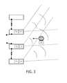
- FIG. 3 depicts schematically an example an automatic fare collection system upgraded according to the invention
- FIG. 4 depicts schematically an example of architecture of a wireless unit according to the invention.
- the invention may apply to any type of contactless system where a portable contactless device is intended to establish a communication session with a contactless reader.
- the portable contactless device may be any device associated with a user.
- the portable contactless device may be a mobile phone, a tablet, a wearable device (like a watch or a bracelet) or an Electronic Funds Transfer Terminal for payment.
- the contactless reader is a fixed device like access control machine for transport network or a building.
- wireless unit and “wireless device” are considered to have the same meaning in this specification.
- FIG. 1 shows an example of system SY including a contactless reader D 1 , a wireless unit D 3 and a portable contactless device D 2 according to the invention.
- the contactless reader D 1 comprises a communication interface NFC- 1 able to communicate according to a standard belonging to Near Field Communication domain.
- the contactless reader D 1 may be a conventional NFC reader.
- the wireless unit D 3 comprises a communication interface NFC- 2 able to communicate according to the same standard as the communication interface NFC- 1 .
- a communication channel C 1 may be established using a NFC protocol between the interfaces NFC- 1 and NFC- 2 .
- the wireless unit D 3 is set to establish a communication channel C 2 with the portable contactless device D 2 through the communication interface UWB- 1 .
- the wireless unit D 3 comprises a bridge agent M 1 configured to establishing a bridge between the communications interfaces NFC- 2 and UWB- 1 only if the detected position of the portable device D 2 matches with the contactless reader D 1 .
- the bridge agent M 1 is adapted to establish a bridge between the contactless reader D 1 and the portable device D 2 through said first and second communication channels C 1 and C 2 only if the detected position of the portable device D 2 matches with the location of the contactless reader D 1 .
- the portable contactless device D 2 comprises a communication interface NFC- 3 able to communicate according to the same standard as the communication interface NFC- 1 .
- a communication channel C 3 may be established using a NFC protocol between the interfaces NFC- 1 and NFC- 3 when the portable contactless device D 2 is placed close to the reader D 1 .
- the portable contactless device D 2 comprises a communication interface UWB- 2 configured to communicate according to the same standard as the communication interface UWB- 1 .
- a communication channel C 2 may be established using a UWB (Ultra-Wide Band or Ultra-Wideband) protocol between the interfaces UWB- 1 and UWB- 2 .
- UWB Ultra-Wide Band
- UWB is defined by IEEE 802.15.4a standard.
- Conventional radio transmissions systems transmit information by varying the power level, frequency, and/or phase of a sinusoidal wave.
- UWB transmit information by generating radio energy at specific time intervals and occupying a large bandwidth, thus enabling pulse-position or time modulation.
- the information can also be modulated on UWB signals (pulses) by encoding the polarity of the pulse, its amplitude and/or by using orthogonal pulses.
- UWB pulses can be sent sporadically at relatively low pulse rates to support time or position modulation.
- An important aspect of UWB technology is the ability for a UWB radio system to measure the distance between two communicating objects and to detect the position of a communicating object relative to another communicating object with an accurate precision.
- a signal with ultra-wide bandwidth is generated using electrical short, baseband pulses (100 ps to 1 ns. Data transmission is made through pulse modulation: either Amplitude, or position or phase modulation.
- the Base-band pulses are applied directly to the antenna. This technology may be used thanks to low cost equipment with minimal RF components.
- UWB signals are typically modulated pulse trains, usually very short pulse duration (i.e. ⁇ 1 ns). Uniform or non-uniform inter-pulse spacing may be set. Pulse repetition frequency (PRF) can range from hundreds of thousands to billions of pulses/second. Modulation techniques include pulse-position modulation, binary phase-shift keying and others.
- UWB may be set to use Time hopping sequence, where Time hopping Sequence (THS) is predictable to user who knows a specific secret so that pulses appear random unless the user know the secret allowing to identify the time hopping sequence.
- THS Time hopping Sequence
- UWB technology is able to resist to Channel Impairments (interferences) because multiple paths are distinguishable. It can be implemented to be robust to interference and to reliably manage anti-collision.
- the data transmission rate via the UWB technology is so high that it has no significant impact on the transmission between the contactless reader D 1 and the portable contactless device D 2 .
- the contactless reader D 1 , the portable contactless device D 2 and wireless unit D 3 are assumed to have architectures similar to those described at FIG. 1 .
- the contactless reader D 1 and the wireless unit D 3 establish a communication channel C 1 .
- they can establish a NFC channel for instance.
- the contactless reader D 1 may send a command through the communication channel C 1 and the command is forwarded to the portable device D 2 through the communication channel C 2 .
- a response to the command can also take the same path in opposite sense.
- the contactless reader D 1 can complete a transaction with the portable contactless device D 2 even if these devices are separated by a distance greater than the distance required for a conventional NFC transaction.
- the bridge i.e. communication link
- the bridge i.e. communication link
- the contactless reader D 1 is established only if the portable contactless device D 2 has a location that matches with the location of the contactless reader D 1 .
- the invention allows to run a transaction with the contactless reader D 1 only if this reader D 1 is the one which is targeted by the user which brings the portable contactless device D 2 .
- the automatic fare collection system comprises three gates which are configured to allow access only to authorized users. An authorized user is assumed to bring a personal token like the portable contactless device D 2 .
- each gate comprises its own NFC reader (D 1 , D 1 A, respectively D 1 B) and its own wireless unit (D 3 , D 3 A, respectively D 3 B) placed near the NFC reader.
- the step sequence described at FIG. 2 can be run.
- the wireless unit D 3 can determine that the user is in front of the gate associated with the contactless reader D 1 , even if the user must still walk several meters to reach the gate.
- the NFC transaction allows the system to anticipate the gate opening.
- No specific gesture is required from the user: he just has to bring the portable contactless device D 2 , in a pocket, a bag or as a wearable object for example.
- the wireless unit D 3 can also determine the movement direction of the portable contactless device D 2 so as to take into account the walk direction of the user.
- the selection of the relevant gate i.e. relevant NFC reader
- the movement direction may be computed from a sequence of measures of the device position.
- each gate has its own NFC reader and a single wireless unit D 3 is associated with the full automatic fare collection system.
- the wireless unit D 3 can connect each of the NFC readers through a communication channel different from NFC.
- the wireless unit D 3 may communicate with each of the NFC readers through a wired channel.
- they may use a wireless protocol like Bluetooth® or any contactless technology having an appropriate range.
- the wireless unit D 3 can be configured to manage several UWB channels in parallel in order to establish simultaneous channels with as many portable contactless devices. Then identification of the targeted contactless reader (i.e. gate intended to be used by the user) and establishment of the relevant bridge may be done when the accuracy of the position/movement of the portable contactless device reaches a preset threshold.
- identification of the targeted contactless reader i.e. gate intended to be used by the user
- establishment of the relevant bridge may be done when the accuracy of the position/movement of the portable contactless device reaches a preset threshold.
- FIG. 4 depicts schematically the architecture of the wireless unit D 3 according to an example of the invention.
- the wireless unit D 3 (also named R-Link Reader Proxy) comprises an RF antenna configured to communicate through ISO/IEC 14443 standard with a conventional NFC reader.
- the wireless unit D 3 comprises an Active Boost Contactless Front-End connected to the RF antenna.
- the Active Boost Contactless Front-End is configured to get energy from the electromagnetic field generated by the NFC reader (i.e. Power extractor feature). It is assumed that the extracted energy allows to power the wireless unit D 3 (i.e. without battery).
- the Active Boost Contactless Front-End is configured to retrieve a clock reference (or frequency reference) from the electromagnetic field generated by the NFC reader (i.e. Clock extractor feature).
- the Active Boost Contactless Front-End is also configured to receive transaction messages from the NFC reader and to transmit response to the NFC reader by modulating the reader magnetic field as described in ISO/IEC 14443 standard.
- the wireless unit D 3 comprises a UWB antenna and a UWB controller in charge of managing the UWB interface (R-Link interface).
- the UWB interface is configured with the following parameters and operating mode: an impulse Ultra wide band signal generated using short baseband pulses from 100 picosecond to 1 nanosecond, using pulse position modulation for data transmission or binary phase shift keying, where a non-uniform inter pulse spacing is used.
- the pulse repetition frequency (PRF) can range from hundreds of thousands to billions of pulse/seconds.
- This impulse Ultra wide band uses a predictable time hopping sequence technics (THS) where pulses appear random.
- the UWB interface is designed to manage anti-collision mechanism. It is adapted to select one portable device among a plurality of devices.
- the UWB controller is configured so that the UWB controller uses the reference clock (13.56 MHz) extracted from the NFC reader field by the Active Boost Contactless Front-End.
- the wireless unit can be configured to extract a frequency from the electromagnetic field generated by the contactless reader D 1 and to use the extracted frequency as a base reference for managing the UWB communication.
- the wireless unit D 3 comprises an application controller (Application Micro Controller) connected to both the Active Boost Contactless Front-End and the UWB controller.
- the application controller is configured to run a direct NFC transaction with a NFC reader through the Active Boost Contactless Front-End and RF antenna. (i.e. corresponding to the communication channel C 3 of FIG. 1 )
- the application controller is also configured to acts as a bridge (e.g. range extender) between the NFC reader and a portable contactless device equipped with its own UWB interface. (i.e. corresponding to combination of communication channels C 1 and C 2 of FIG. 1 )
- the application controller may be configured to encapsulate NFC messages into UWB messages and extract NFC messages from UWB messages.
- the application controller may be configured to translate incoming NFC messages in outgoing UWB messages and to translate incoming UWB messages into outgoing NFC messages.
- the application controller is configured to establish the bridge only if the detected position of the portable contactless device matches with the location of the NFC reader.
- the matching operation may implemented through a comparison between the measured position and a preset physical area associated with the NFC reader.
- the application controller may be configured to take into account both the detected position and movement direction of the portable contactless device relative to the NFC reader.
- the application controller may be configured to take into account both the detected position and movement direction of the portable contactless device relative to the NFC reader.
- VDD is the DC Power supply created thanks to the energy extracted from the NFC RF field, usually it is a 3.3 Vdc.
- VSS is the ground (i.e. 0 Vdc).
- FIG. 5 depicts schematically the architecture of the portable contactless device D 2 according to an example of the invention.
- the portable contactless device D 2 (wearable) comprises an NFC antenna configured to communicate through ISO/IEC 14443 standard with a conventional NFC reader.
- the portable contactless device D 2 comprises a secure element dedicated to manage NFC transactions.
- the portable contactless device D 2 comprises a UWB antenna and a UWB interface (R-Link interface).
- the UWB interface is configured communicate with the UWB interface of the wireless unit according to the invention.
- the portable contactless device D 2 comprises a host controller connected to both the secure element and the UWB interface.
- the host controller is configured to redirect data between the UWB interface and the secure element.
- the host controller may be configured to extract NFC messages from incoming UWB messages and to encapsulate NFC messages into outgoing UWB messages.
- the host controller may be configured to translate incoming UWB messages in NFC messages (or any other communication protocol like ISO7816, SWP or SPI) and to translate messages coming from the secure element into outgoing UWB messages.
- NFC messages or any other communication protocol like ISO7816, SWP or SPI
- the host controller can retrieve data received by the UWB interface and send the data to the secure element via a contact ISO7816 interface.
- the UWB interface may be directly connected to the secure element.
- the UWB interface is configured to directly exchange data with the secure element.
- the portable contactless device D 2 may comprise a Sensors and a Bluetooth® Low Energy interface (BLE controller). These features are not required to implement the present invention.
- a user can access a usual automatic fare collection system by tapping the portable contactless device D 2 to the NFC reader.
- the user can also access an automatic fare collection system upgraded according to the invention without any specific gesture.
- VDD is the DC Power supply. Usually it is a 3.3 Vdc. The power may come from a battery (not shown).
- VSS is the ground (i.e. 0 Vdc).
- the contactless reader may communicate with a radio technology different from the ISO14443. It may be compliant with ISO18092 or ISO15693 standards for instance.
- the invention is not limited to NFC communication and may apply to any kinds of contactless communication where the range need to be extended.
- the invention is not limited to the described embodiments or examples.
- the invention may apply to payment transactions, access to a service, or access to a building.
Landscapes
- Engineering & Computer Science (AREA)
- Computer Networks & Wireless Communication (AREA)
- Computer Hardware Design (AREA)
- Microelectronics & Electronic Packaging (AREA)
- Physics & Mathematics (AREA)
- General Physics & Mathematics (AREA)
- Theoretical Computer Science (AREA)
- Signal Processing (AREA)
- Mobile Radio Communication Systems (AREA)
- Near-Field Transmission Systems (AREA)
- Telephone Function (AREA)
Abstract
-
- establishing a first channel between the contactless reader and a wireless unit,
- establishing between the wireless unit and the portable device a second channel using a second wireless technology which is configured:
- to operate with a range greater than that of said first wireless technology,
- to detect the position of the portable device with respect to the wireless unit,
- to handle an anti-collision phase,
- establishing a bridge between the contactless reader and the portable device through said first and second channels only if the detected position of the portable device matches with the contactless reader.
Description
-
- establishing a first communication channel between the contactless reader and a wireless unit,
- establishing between the wireless unit and the portable device a second communication channel using a second wireless technology, said second wireless technology being configured:
- to operate with a range greater than that of said first wireless technology,
- to detect the position of the portable device with respect to the wireless unit,
- to handle an anti-collision phase,
- establishing a bridge between the contactless reader and the portable device through said first and second communication channels only if the detected position of the portable device matches with the contactless reader.
-
- to operate with a range greater than that of said first wireless technology,
- to detect the position of the portable device with respect to the wireless unit, and
- to handle an anti-collision phase.
The wireless unit is configured to establish a bridge between the contactless reader and the portable device through said first and second communication channels only if the detected position of the portable device matches with the contactless reader.
-
- to operate with a range greater than that of said first wireless technology,
- to detect the position of the portable device with respect to the wireless unit, and
- to handle an anti-collision phase.
The portable device is configured to exchange incoming messages generated by the contactless reader and outgoing messages targeting the contactless reader through said second communication channel.
-
- to operate with a range greater than the range of the NFC technology,
- to detect the position of the portable device D2 with respect to the wireless unit D3, and
- to handle an anti-collision phase.
Claims (14)
Applications Claiming Priority (4)
| Application Number | Priority Date | Filing Date | Title |
|---|---|---|---|
| EP16305155 | 2016-02-11 | ||
| EP16305155.0A EP3206305A1 (en) | 2016-02-11 | 2016-02-11 | Method for managing communication between a contactless reader and a portable contactless device |
| EP16305155.0 | 2016-02-11 | ||
| PCT/EP2017/051412 WO2017137249A1 (en) | 2016-02-11 | 2017-01-24 | Method for managing communication between a contactless reader and a portable contactless device |
Publications (2)
| Publication Number | Publication Date |
|---|---|
| US20190052314A1 US20190052314A1 (en) | 2019-02-14 |
| US10382097B2 true US10382097B2 (en) | 2019-08-13 |
Family
ID=55357952
Family Applications (1)
| Application Number | Title | Priority Date | Filing Date |
|---|---|---|---|
| US16/076,894 Active US10382097B2 (en) | 2016-02-11 | 2017-01-24 | Method for managing communication between a contactless reader and a portable contactless device |
Country Status (3)
| Country | Link |
|---|---|
| US (1) | US10382097B2 (en) |
| EP (2) | EP3206305A1 (en) |
| WO (1) | WO2017137249A1 (en) |
Families Citing this family (7)
| Publication number | Priority date | Publication date | Assignee | Title |
|---|---|---|---|---|
| WO2020089484A1 (en) | 2018-11-02 | 2020-05-07 | Assa Abloy Ab | Systems, methods, and devices for access control |
| FR3092217B1 (en) | 2019-01-30 | 2022-11-25 | St Microelectronics Rousset | NFC and UWB communications |
| EP3928113A1 (en) | 2019-03-25 | 2021-12-29 | Assa Abloy Ab | Ultra-wide band device for access control reader system |
| CN113678014A (en) | 2019-03-25 | 2021-11-19 | 亚萨合莱有限公司 | Physical access control system with location-based intent detection |
| KR20210039109A (en) | 2019-10-01 | 2021-04-09 | 삼성전자주식회사 | Electronic device for transmitting/receiving data and method thereof |
| FR3106664B1 (en) * | 2020-01-24 | 2022-02-11 | Xtreamwave | Device for the identification, precise localization and selection of a mobile object among a plurality of objects located nearby. |
| WO2023048721A1 (en) * | 2021-09-24 | 2023-03-30 | Visa International Service Association | System and methods for enabling ultra-wide band in passive devices |
Citations (9)
| Publication number | Priority date | Publication date | Assignee | Title |
|---|---|---|---|---|
| US20050035862A1 (en) * | 2001-05-08 | 2005-02-17 | Wildman Timothy D. | Article locating and tracking apparatus and method |
| US20070073935A1 (en) * | 2005-09-15 | 2007-03-29 | Jong Won Kim | Wireless USB host apparatus supporting UWB |
| US20080212558A1 (en) * | 2005-01-19 | 2008-09-04 | Gemplus | Communication Set Up Between Wireless Devices |
| US20120028579A1 (en) * | 2009-04-09 | 2012-02-02 | Gemalto Sa | Method of detecting a nfc device emulating several contactless cards which may use a plurality of protocols |
| US20130092741A1 (en) * | 2007-09-21 | 2013-04-18 | Michael Loh | Wireless smart card and integrated personal area network, near field communication and contactless payment system |
| US20130203351A1 (en) * | 2012-02-02 | 2013-08-08 | Qualcomm Incorporated | Methods and apparatus for improving the identification of multiple nfc-a devices |
| US20140020081A1 (en) * | 2012-07-16 | 2014-01-16 | Qualcomm Incorporated | Portable Token Device |
| US20150039494A1 (en) * | 2013-08-01 | 2015-02-05 | Mastercard International Incorporated | Paired wearable payment device |
| US20160239795A1 (en) * | 2015-02-18 | 2016-08-18 | Fedex Corporate Services, Inc. | Apparatus, non-transient computer readable media, and methods for automatically quantifying space within a logistics container using a scanning sensor node disposed within the container |
-
2016
- 2016-02-11 EP EP16305155.0A patent/EP3206305A1/en not_active Withdrawn
-
2017
- 2017-01-24 WO PCT/EP2017/051412 patent/WO2017137249A1/en active Application Filing
- 2017-01-24 EP EP17701849.6A patent/EP3375103B1/en active Active
- 2017-01-24 US US16/076,894 patent/US10382097B2/en active Active
Patent Citations (9)
| Publication number | Priority date | Publication date | Assignee | Title |
|---|---|---|---|---|
| US20050035862A1 (en) * | 2001-05-08 | 2005-02-17 | Wildman Timothy D. | Article locating and tracking apparatus and method |
| US20080212558A1 (en) * | 2005-01-19 | 2008-09-04 | Gemplus | Communication Set Up Between Wireless Devices |
| US20070073935A1 (en) * | 2005-09-15 | 2007-03-29 | Jong Won Kim | Wireless USB host apparatus supporting UWB |
| US20130092741A1 (en) * | 2007-09-21 | 2013-04-18 | Michael Loh | Wireless smart card and integrated personal area network, near field communication and contactless payment system |
| US20120028579A1 (en) * | 2009-04-09 | 2012-02-02 | Gemalto Sa | Method of detecting a nfc device emulating several contactless cards which may use a plurality of protocols |
| US20130203351A1 (en) * | 2012-02-02 | 2013-08-08 | Qualcomm Incorporated | Methods and apparatus for improving the identification of multiple nfc-a devices |
| US20140020081A1 (en) * | 2012-07-16 | 2014-01-16 | Qualcomm Incorporated | Portable Token Device |
| US20150039494A1 (en) * | 2013-08-01 | 2015-02-05 | Mastercard International Incorporated | Paired wearable payment device |
| US20160239795A1 (en) * | 2015-02-18 | 2016-08-18 | Fedex Corporate Services, Inc. | Apparatus, non-transient computer readable media, and methods for automatically quantifying space within a logistics container using a scanning sensor node disposed within the container |
Non-Patent Citations (4)
| Title |
|---|
| Connell, Ciaran. "What's the Difference Between Measuring Location by UWB, Wi-Fi, and Bluetooth?", Feb. 2015 (Year: 2015). * |
| International Search Report (PCT/ISA/210) dated Apr. 24, 2017, by the European Patent Office as the International Searching Authority for International Application No. PCT/EP2017/051412. |
| Written Opinion (PCT/ISA/237) dated Apr. 24, 2017, by the European Patent Office as the International Searching Authority for International Application No. PCT/EP2017/051412. |
| Yavari, Mohammadreza. "Indoor Real-Time Positioning Using Ultra-Wideband Technology.", Aug. 2015 (Year: 2015). * |
Also Published As
| Publication number | Publication date |
|---|---|
| US20190052314A1 (en) | 2019-02-14 |
| EP3375103A1 (en) | 2018-09-19 |
| EP3206305A1 (en) | 2017-08-16 |
| WO2017137249A1 (en) | 2017-08-17 |
| EP3375103B1 (en) | 2019-09-11 |
Similar Documents
| Publication | Publication Date | Title |
|---|---|---|
| US10382097B2 (en) | Method for managing communication between a contactless reader and a portable contactless device | |
| US9122903B2 (en) | Method of managing communications with a NFC controller | |
| EP2241031B1 (en) | Switching between multiple coupling modes | |
| EP1869842B1 (en) | Communications apparatus | |
| US20120045989A1 (en) | Device discovery in near-field communication | |
| Timalsina et al. | NFC and its application to mobile payment: Overview and comparison | |
| CN102215050B (en) | Detection method for radio-frequency SIM (Subscriber Identity Module) card collision with low-frequency magnetic communication | |
| EP2805428B1 (en) | Near-field communication (nfc) system and method for private near-field communication | |
| US11301651B2 (en) | Method and device for data transfer between a mobile device and a reader device | |
| US9577743B2 (en) | Communications system having a secure credentials storage device | |
| Nagashree et al. | Near field communication | |
| KR102228653B1 (en) | Tag identification system with improved authentication | |
| Ranganathan et al. | Proximity verification for contactless access control and authentication systems | |
| Kumar | Near field communication | |
| CN102412870A (en) | Fast-access near field wireless communication module used for controlling communication range | |
| JP5079953B2 (en) | Non-contact type IC card reader / writer system | |
| Bolić et al. | Proximity detection with RFID in the Internet of Things | |
| CN109727357A (en) | Electronic lock system based on UWB two-dimensional localization | |
| Hancke | Security of proximity identification systems | |
| Dudwadkar et al. | Near field communication in mobile phones | |
| EP2816737A1 (en) | Secure near field communication | |
| KR100774362B1 (en) | Control Process using this Control Installation using RFID and UWB Communication | |
| Wang | Study on several promising short-range wireless communication technologies | |
| CN103178907B (en) | Improve the method for collision detection success rate | |
| CharanPuladas | Near field communication: programming and security |
Legal Events
| Date | Code | Title | Description |
|---|---|---|---|
| AS | Assignment |
Owner name: GEMALTO SA, FRANCE Free format text: ASSIGNMENT OF ASSIGNORS INTEREST;ASSIGNOR:CARUANA, JEAN-PAUL;REEL/FRAME:046600/0646 Effective date: 20180613 |
|
| FEPP | Fee payment procedure |
Free format text: ENTITY STATUS SET TO UNDISCOUNTED (ORIGINAL EVENT CODE: BIG.); ENTITY STATUS OF PATENT OWNER: LARGE ENTITY |
|
| STPP | Information on status: patent application and granting procedure in general |
Free format text: DOCKETED NEW CASE - READY FOR EXAMINATION |
|
| STPP | Information on status: patent application and granting procedure in general |
Free format text: NOTICE OF ALLOWANCE MAILED -- APPLICATION RECEIVED IN OFFICE OF PUBLICATIONS |
|
| STCF | Information on status: patent grant |
Free format text: PATENTED CASE |
|
| MAFP | Maintenance fee payment |
Free format text: PAYMENT OF MAINTENANCE FEE, 4TH YEAR, LARGE ENTITY (ORIGINAL EVENT CODE: M1551); ENTITY STATUS OF PATENT OWNER: LARGE ENTITY Year of fee payment: 4 |
|
| AS | Assignment |
Owner name: THALES DIS FRANCE SA, FRANCE Free format text: CHANGE OF NAME;ASSIGNOR:GEMALTO SA;REEL/FRAME:064716/0634 Effective date: 20190716 |
|
| AS | Assignment |
Owner name: THALES DIS FRANCE SAS, FRANCE Free format text: ASSIGNMENT OF ASSIGNORS INTEREST;ASSIGNOR:THALES DIS FRANCE SA;REEL/FRAME:064792/0714 Effective date: 20211215 |