US10380725B2 - Image processing apparatus, image processing method, and storage medium - Google Patents
Image processing apparatus, image processing method, and storage medium Download PDFInfo
- Publication number
- US10380725B2 US10380725B2 US15/353,158 US201615353158A US10380725B2 US 10380725 B2 US10380725 B2 US 10380725B2 US 201615353158 A US201615353158 A US 201615353158A US 10380725 B2 US10380725 B2 US 10380725B2
- Authority
- US
- United States
- Prior art keywords
- gradation
- image
- range
- gradation value
- converted
- Prior art date
- Legal status (The legal status is an assumption and is not a legal conclusion. Google has not performed a legal analysis and makes no representation as to the accuracy of the status listed.)
- Active, expires
Links
- 238000012545 processing Methods 0.000 title claims abstract description 85
- 238000003672 processing method Methods 0.000 title claims description 9
- 238000006243 chemical reaction Methods 0.000 claims abstract description 108
- 238000000034 method Methods 0.000 claims abstract description 52
- 238000012937 correction Methods 0.000 description 45
- 230000015556 catabolic process Effects 0.000 description 8
- 238000006731 degradation reaction Methods 0.000 description 8
- 239000000872 buffer Substances 0.000 description 7
- 230000007423 decrease Effects 0.000 description 7
- 230000009467 reduction Effects 0.000 description 7
- 230000006870 function Effects 0.000 description 6
- 238000010586 diagram Methods 0.000 description 3
- 230000007613 environmental effect Effects 0.000 description 3
- 238000003384 imaging method Methods 0.000 description 3
- 238000012986 modification Methods 0.000 description 3
- 230000004048 modification Effects 0.000 description 3
- 230000008859 change Effects 0.000 description 2
- 230000003247 decreasing effect Effects 0.000 description 2
- 230000000694 effects Effects 0.000 description 2
- 238000005401 electroluminescence Methods 0.000 description 2
- 230000011218 segmentation Effects 0.000 description 2
- 230000008901 benefit Effects 0.000 description 1
- 238000007796 conventional method Methods 0.000 description 1
- 239000004973 liquid crystal related substance Substances 0.000 description 1
- 230000003287 optical effect Effects 0.000 description 1
- 230000002269 spontaneous effect Effects 0.000 description 1
Images


Classifications
-
- G06T5/92—
-
- G06T5/94—
-
- G—PHYSICS
- G06—COMPUTING; CALCULATING OR COUNTING
- G06T—IMAGE DATA PROCESSING OR GENERATION, IN GENERAL
- G06T5/00—Image enhancement or restoration
- G06T5/007—Dynamic range modification
- G06T5/009—Global, i.e. based on properties of the image as a whole
-
- G—PHYSICS
- G06—COMPUTING; CALCULATING OR COUNTING
- G06T—IMAGE DATA PROCESSING OR GENERATION, IN GENERAL
- G06T5/00—Image enhancement or restoration
- G06T5/007—Dynamic range modification
- G06T5/008—Local, e.g. shadow enhancement
-
- G—PHYSICS
- G06—COMPUTING; CALCULATING OR COUNTING
- G06T—IMAGE DATA PROCESSING OR GENERATION, IN GENERAL
- G06T5/00—Image enhancement or restoration
- G06T5/20—Image enhancement or restoration by the use of local operators
-
- H—ELECTRICITY
- H04—ELECTRIC COMMUNICATION TECHNIQUE
- H04N—PICTORIAL COMMUNICATION, e.g. TELEVISION
- H04N23/00—Cameras or camera modules comprising electronic image sensors; Control thereof
- H04N23/60—Control of cameras or camera modules
- H04N23/63—Control of cameras or camera modules by using electronic viewfinders
-
- H—ELECTRICITY
- H04—ELECTRIC COMMUNICATION TECHNIQUE
- H04N—PICTORIAL COMMUNICATION, e.g. TELEVISION
- H04N5/00—Details of television systems
- H04N5/14—Picture signal circuitry for video frequency region
- H04N5/20—Circuitry for controlling amplitude response
- H04N5/202—Gamma control
-
- H04N5/23293—
-
- G—PHYSICS
- G06—COMPUTING; CALCULATING OR COUNTING
- G06T—IMAGE DATA PROCESSING OR GENERATION, IN GENERAL
- G06T2207/00—Indexing scheme for image analysis or image enhancement
- G06T2207/10—Image acquisition modality
- G06T2207/10024—Color image
-
- G—PHYSICS
- G06—COMPUTING; CALCULATING OR COUNTING
- G06T—IMAGE DATA PROCESSING OR GENERATION, IN GENERAL
- G06T2207/00—Indexing scheme for image analysis or image enhancement
- G06T2207/20—Special algorithmic details
- G06T2207/20172—Image enhancement details
- G06T2207/20208—High dynamic range [HDR] image processing
-
- H—ELECTRICITY
- H04—ELECTRIC COMMUNICATION TECHNIQUE
- H04N—PICTORIAL COMMUNICATION, e.g. TELEVISION
- H04N23/00—Cameras or camera modules comprising electronic image sensors; Control thereof
- H04N23/70—Circuitry for compensating brightness variation in the scene
- H04N23/741—Circuitry for compensating brightness variation in the scene by increasing the dynamic range of the image compared to the dynamic range of the electronic image sensors
-
- H04N5/2355—
Definitions
- the present disclosure relates to an image processing apparatus, an image processing method, and a storage medium, and is particularly suitable for being used to improve the image quality of images.
- a general video content is generated on an assumption that a display apparatus has a dynamic range of about 2000.
- some display apparatuses actually used for viewing have a narrow dynamic range because of performance restrictions.
- an assumed content view is not achieved because of the degradation of the dynamic range of a display apparatus due to a bright viewing environment or the degradation of the dynamic range of a projector due to re-reflection of spontaneous light from the side of a viewer.
- the viewer views a content under degraded contrast conditions.
- tone curve correction processing is performed.
- the image quality may be degraded by blown-out highlights and blocked-up shadows as side effects resulting from the raised contrast in an intermediate portion through the tone curve correction processing.
- the dynamic range of the display apparatus decreases when viewing the display apparatus in a bright environment. Accordingly, gamma correction for raising the contrast may be performed according to an ambient illuminance of the display apparatus. Also in this case, the image quality may be degraded by blown-out highlights and blocked-up shadows similar to the case where the tone curve correction processing is performed.
- Japanese Patent Application Laid-Open No. 2009-17200 discusses a technique for changing a use ratio of a tone curve for raising a luminance and a use ratio of a tone curve for reducing the luminance based on histograms of black and white side sections.
- Japanese Patent Application Laid-Open No. 2009-17200 in which an entire screen is uniformly corrected for the degradation of the dynamic range of a display apparatus, effects of the improved contrast are effective in some portions and not in other portions.
- Japanese Patent Application Laid-Open No. 10-293841 discusses a technique for raising the contrast and sharpness along with the increase of difference between the average gradation value of an image and the average gradation value of neighborhood pixels of a target pixel.
- Japanese Patent Application Laid-Open No. 2005-312008 discusses a technique for changing a coefficient of an unsharp-mask in sharpness processing based on the average gradation value of neighborhood pixels of a target pixel.
- an image processing apparatus includes, a first acquisition unit configured to, in order to generate a converted image having a narrower dynamic range than an input image, acquire gradation values of a plurality of neighborhood pixels positioned in a predetermined range from a processing target pixel of the input image, a second acquisition unit configured to acquire conversion information from a holding unit holding the conversion information used to generate the converted image having a narrower dynamic range than the input image, and a determination unit configured to determine a gradation value of a pixel on the converted image corresponding to the processing target pixel by using the gradation values of the plurality of neighborhood pixels acquired by the first acquisition unit and the conversion information acquired by the second acquisition unit.
- FIG. 1 illustrates a relation between a dynamic range and contrast.
- FIG. 2 illustrates a configuration of a display apparatus.
- FIG. 3 illustrates a first exemplary embodiment of a configuration of a contrast correction circuit.
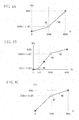
- FIGS. 4A, 4B, and 4C illustrate tone curves in a light gradation portion, an intermediate gradation portion, and a dark gradation portion, respectively.
- FIGS. 5A and 5B illustrate ratio conversion tables for three different tone curves.
- FIG. 6 illustrates a tone curve in an intermediate light gradation portion.
- FIG. 7 illustrates a ratio conversion table for four different tone curves.
- FIG. 8 illustrates a second exemplary embodiment of the configuration of the contrast correction circuit.
- FIG. 9 illustrates a wide range tone curve.
- FIGS. 10A and 10B illustrate a first and a second examples of a part of the wide range tone curve.
- FIGS. 11A and 11B illustrate a third and a fourth examples of a part of the wide range tone curve.
- FIG. 1 illustrates an example of a relation between a content, the dynamic range of the display apparatus, and the contrast thereof.
- a vertical axis indicates a luminance. The higher a position on the axis, the higher the luminance.
- a luminance range 11 is the luminance range assumed by the content.
- Contrast 12 is contrast between certain gradations A and B in the content.
- a luminance range 13 is the luminance range to be displayed by the display apparatus.
- Contrast 14 is contrast between certain gradations a and b of the display apparatus.
- Contrast 15 is contrast between gradations a′ and b′ with which the contrast is expanded by performing processing according to the present exemplary embodiment (described below).
- a ratio of the luminance ranges used for the content and the display apparatus is equal to the dynamic range of the content or the display apparatus.
- the dynamic range of BT709 i.e., a representative standard in TV broadcast, is only about 850. This dynamic range is so narrow that blown-out highlights may occur. Therefore, with a photographing camera, a high gradation region is folded by 200 to 400% on a gamma curve. Accordingly, the dynamic range assumed by the content is about 2000 to 3000. However, there are cases where the dynamic range actually displayed is only 500 due to the performance of the display apparatus and where only about 100 by the influence of outdoor daylight and reflected light of display.
- the contrast 12 between the gradations A and B is A/B.
- the luminance range 13 displayed by the display apparatus is narrower than the luminance range 11 assumed by the content, in other words, when the content is displayed on a display apparatus having a dynamic range narrower than the dynamic range assumed by the content, the gradation A becomes the gradation a and the gradation B becomes the gradation b. Therefore, the contrast between the gradations a and b corresponding to the gradations A and B, respectively, is a/b. In this case, a condition a/b ⁇ A/B is satisfied.
- the following exemplary embodiments perform contrast expansion processing in which the gradation a is changed to the gradation a′ which is higher than the gradation a, the gradation b is changed to the gradation b′ which is lower than the gradation b, or both pieces of processing are performed.
- the contrast 15 between the gradations a′ and b′ is larger than the contrast 14 between the gradations a and b. More specifically, a condition a′/b′>a/b is satisfied.
- FIG. 2 is a block diagram illustrating an exemplary embodiment of an overall configuration of a display apparatus 20 including an image quality processing device.
- a gamma system image quality adjustment circuit 21 performs gamma system image quality correction on an input image.
- a dynamic range estimation circuit 22 calculates a reduction ratio of the dynamic range.
- a contrast correction circuit 23 corrects the contrast of an image that has undergone the gamma system image quality correction according to the narrowness of the dynamic range.
- a linear system image quality adjustment circuit 24 performs linear system image quality correction on an image that has undergone the gamma system image quality correction.
- a panel driver 25 converts an image signal that has undergone the linear system image quality correction into a display panel drive signal.
- a display panel 26 displays an image.
- An input image can be obtained, for example, through an external input or by decoding a signal received by a TV tuner.
- An image (input image) input to the display apparatus 20 is normally a gamma system image to which the gamma value 2.2 is applied.
- the gamma system image quality adjustment circuit 21 performs gamma system image processing such as gamma system scaling on the input image.
- the dynamic range estimation circuit 22 estimates the actually displayed dynamic range based on an original dynamic range of the display panel 26 and an environmental illuminance (an ambient illuminance of the display apparatus 20 ).
- the original dynamic range of the display panel 26 is obtained by measuring a white luminance, a black luminance, or a luminance for a gradation value 1 of the display panel 26 at the time of shipment.
- a user sets such a value as 500 or 1000 as the dynamic range of the display panel 26 .
- the display apparatus 20 is provided with an illuminance sensor (not illustrated).
- the illuminance sensor senses the environmental illuminance. The larger the ambient illuminance of the display apparatus 20 (more specifically, the lighter the periphery thereof), the narrower the dynamic range of the display panel 26 .
- the user sets how much the dynamic range is narrowed with respect to the original dynamic range of the display panel 26 . For example, the user sets such a value as 1 ⁇ 5 or 1/20.
- the user also needs to set the dynamic range assumed by the content displayed by the display apparatus 20 .
- the dynamic range assumed by the content displayed by the display apparatus 20 As described above, normal broadcasting images are assumed to have a dynamic range of about 2000. Therefore, it is necessary that the initial value of the dynamic range assumed by the content is set to 2000 and that the assumed dynamic range is changeable by the user depending on the content displayed by the display apparatus 20 .
- the dynamic range estimation circuit 22 calculates the reduction ratio of the dynamic range as follows.
- a dynamic range reduction ratio SK to be obtained is represented by the following formula (1).
- SK ( DD/CD ) ⁇ KK (1)
- the dynamic range assumed by the content is 2000
- the dynamic range of the display panel 26 is 500
- the dynamic range is reduced to 1 ⁇ 3 by an ambient light
- the dynamic range reduction ratio SK becomes 1/12 (formula (2)).
- the contrast correction circuit 23 derives the dynamic range magnification GDR by obtaining the reciprocal of the dynamic range reduction ratio SK calculated by the dynamic range estimation circuit 22 .
- the contrast correction circuit 23 performs contrast correction processing based on the dynamic range magnification GDR on an image signal output from the gamma system image quality adjustment circuit 21 .
- the contrast correction circuit 23 will be described in detail below with reference to FIG. 3 .
- the dynamic range magnification GDR may be derived by the dynamic range estimation circuit 22 .
- the contrast correction circuit 23 outputs the image signal to the linear system image quality adjustment circuit 24 without performing contrast correction on the image signal output from the gamma system image quality adjustment circuit 21 .
- the linear system image quality adjustment circuit 24 converts the image signal into a linear system signal and then performs linear system edge intensifying processing on the linear system signal to adjust the image quality.
- FIG. 2 illustrates as an example of a case where an image processing apparatus is built in the display apparatus 20 .
- an image quality adjustment apparatus incorporating an image processing apparatus an image quality processing apparatus may be configured to be connected to a preceding stage of a general display apparatus.
- an imaging apparatus incorporating an image processing apparatus an image processing apparatus may be configured to be connected to the following stage of a general imaging apparatus.
- FIG. 3 is a block diagram illustrating an exemplary embodiment of a configuration of the contrast correction circuit 23 in the image processing apparatus according to the present exemplary embodiment.
- line buffers 31 temporarily stores an input image signal.
- a Gaussian filter 32 calculates a neighborhood average gradation value which is an average value of the gradation values of neighborhood pixels of a processing target pixel.
- a light portion gamma conversion unit 33 expands a light gradation portion.
- An intermediate portion gamma conversion unit 34 expands an intermediate gradation portion.
- a dark portion gamma conversion unit 35 expands a dark gradation portion.
- the light gradation portion refers to a relatively light region (a region having large gradation values).
- the dark gradation portion refers to a relatively dark region (a region having small gradation values).
- the intermediate gradation portion refers to a region having brightness between the light and the dark gradation portions (a region having intermediate gradation values).
- a use ratio calculation unit 36 derives a use ratio for outputs of the light portion gamma conversion unit 33 , the intermediate portion gamma conversion unit 34 , and the dark portion gamma conversion unit 35 based on the neighborhood average gradation value.
- a multiplier 37 multiplies the image signal with the expanded light gradation portion by the use ratio for the output of the light portion gamma conversion unit 33 .
- a multiplier 38 multiplies the image signal with the expanded intermediate gradation portion by the use ratio for the output of the intermediate portion gamma conversion unit 34 .
- a multiplier 39 multiplies the image signal with the expanded dark gradation portion by the use ratio for the output of the dark portion gamma conversion unit 35 .
- the contrast correction circuit 23 converts the color space of the image signal into a luminance-and-chrominance (YPbPr) color space and performs processing only on the value of a luminance signal (Y). Then, the contrast correction circuit 23 adds the value of the luminance signal (Y) processed by the contrast correction circuit 23 and the value of the chrominance signal (PbPr) and returns the color space of an image signal to the RGB color space.
- the line buffer 31 holds an image signal only for the number of lines required by the Gaussian filter 32 .
- the line buffer 31 holds the image signal for 9 lines.
- the Gaussian filter 32 performs calculation by using only the gradation value of the luminance signal (Y). Therefore, the line buffer 31 needs only to hold the gradation value of the luminance signal (Y) for 9 lines, and to hold a chrominance signal (PbPr) for 5 lines, which is a time period until the processing target pixel can be calculated, to be output in synchronization with the luminance signal (Y).
- the Gaussian filter 32 calculates the average value of the gradation values of pixels in the neighborhood region of the current processing target pixel.
- the Gaussian filter 32 sets weights by using the Gaussian distribution (setting larger weights for average value calculation for pixels closer to the processing target pixel, and setting smaller weights for pixels farther from the processing target pixel).
- An average value filter may be used instead of a Gaussian filter. In this case, a circuit scale decreases although the influence of pixels distant from the processing target pixel increases. If the 9 ⁇ 9 filter size is too large, a smaller size (7 ⁇ 7 or 5 ⁇ 5) Gaussian filter may be used since the accuracy of the correction processing result only slightly degrades.
- a representative value of the gradation values of pixels in the neighborhood region of the processing target pixel may be derived without using the neighborhood average gradation value.
- the representative value can be derived by performing super pixel processing or a split-and-merge method as a kind of segmentation. Performing segmentation of the processing target image enables determining an image region including the processing target pixel. Therefore, the contrast can be suitably corrected by using the average value of the gradation values of the image region.
- the degree of the expansion of the gradation portion can be achieved by changing an inclination of a tone curve of each gradation portion to be expanded, according to the dynamic range magnification GDR.
- the inclination of the tone curve is represented by the ratio of an increased amount of the gradation value of an output pixel when the gradation value of an input pixel is increased by an increased amount to the increased amount of the gradation value of the input pixel.
- the contrast correction circuit 23 After the gradation value of the luminance signal (Y) is processed by the light portion gamma conversion unit 33 , the intermediate portion gamma conversion unit 34 , and the dark portion gamma conversion unit 35 , the contrast correction circuit 23 outputs three different luminance signals (Y) in which the respective gradation values are converted to expand mutually different gradation portions.
- the light portion gamma conversion unit 33 , the intermediate portion gamma conversion unit 34 , and the dark portion gamma conversion unit 35 will be described in detail below with reference to FIGS. 4A, 4B, and 4C , respectively.
- the use ratio calculation unit 36 determines the use ratios for the outputs of the light portion gamma conversion unit 33 , the intermediate portion gamma conversion unit 34 , and the dark portion gamma conversion unit 35 .
- the ratio conversion table will be described in detail below with reference to FIGS. 5A and 5B .
- the multipliers 37 , 38 , and 39 multiply the respective outputs (image signals with the expanded light, intermediate, and dark gradation portions) from the light portion gamma conversion unit 33 , the intermediate portion gamma conversion unit 34 , and the dark portion gamma conversion unit 35 by the respective use ratios.
- An adder 40 adds the three outputs (signals obtained by multiplying the expanded light, intermediate, and dark gradation portions by the respective use ratios) from the multipliers 37 , 38 , and 39 , respectively.
- the outputs of the light portion gamma conversion unit 33 , the intermediate portion gamma conversion unit 34 , and the dark portion gamma conversion unit 35 are mixed to obtain the luminance signal (Y) after correction processing.
- the luminance signal (Y) after correction processing and the chrominance (PbPr) with which a delay amount is adjusted by the line buffer 31 are combined and output to the linear system image quality adjustment circuit 24 as an output image.
- the linear system image quality adjustment circuit 24 When an image signal in the RGB color space is required in its post-process, normal YPbPr-RGB conversion will be performed.
- FIGS. 4A, 4B, and 4C illustrate examples of tone curves in the light, the intermediate, and the dark gradation portions, respectively.
- FIG. 4A illustrates an example of a tone curve for the light gradation portion.
- FIG. 4B illustrates an example of a tone curve for the intermediate gradation portion.
- FIG. 4C illustrates an example of a tone curve for the dark gradation portion.
- a horizontal axis Yi indicates a gamma system 12-bit gradation value as the gradation value of the luminance signal (Y) before correction
- each of vertical axes HYo, MYo, and LYo indicates the gamma system 12-bit gradation value as the gradation value of the luminance signal (Y) after correction.
- the light gradation portion (a portion with the gradation value 2048 or larger out of all (4095) gradations) is assumed to be a light portion.
- the inclination of a light gradation portion tone curve 41 in the light portion is assumed to be 1 or larger (preferably larger than 1).
- the light gradation portion of the luminance signal (Y) output from the light portion gamma conversion unit 33 is expanded to a further extent than the light gradation portion of the luminance signal (Y) input to the light portion gamma conversion unit 33 , resulting in the raised contrast of the light gradation portion.
- the boundary between the light and the dark gradation portions is not limited to the gradation value 2048, and may be a predetermined value other than 2048 (for example, 1024).
- the magnitude (degree) of the inclination of the light gradation portion of the light gradation portion tone curve 41 can be controlled by a control point 42 on the light gradation portion tone curve 41 .
- the output value HYo at the control point 42 on the light gradation portion tone curve 41 is made smaller than 2048, and the inclination of the light portion of the light gradation portion tone curve 41 is increased.
- a coefficient GP is used to raise the contrast according to the dynamic range magnification GDR.
- the dynamic range magnification GDR can be converted into the coefficient GP by the following formula (3).
- GP k ⁇ GDR j (3) where k>0 and j>0.
- the coefficient GP is 0.06 when the dynamic range magnification GDR is 12, and is 0.123 when the dynamic range magnification GDR is 64.
- the above-described values of the constants k and j are examples, and may be suitably adjusted.
- adding an element of a neighborhood average gradation value LPFY to the calculation formula of the coefficient GP enables providing a higher contrast to a lighter gradation portion or providing a higher contrast to a darker gradation portion.
- applying the larger coefficient GP for the larger neighborhood average gradation value LPFY enables providing a higher contrast to a lighter gradation portion.
- applying the larger coefficient GP for the smaller neighborhood average gradation value LPFY enables providing a higher contrast to a darker gradation portion.
- the intermediate gradation portion (a portion with the gradation value 512 to 2048 out of all (4095) gradations) is assumed to be an intermediate portion.
- the inclination of an intermediate gradation portion tone curve 43 in the intermediate portion is assumed to be 1 or larger (preferably larger than 1).
- the intermediate gradation portion of the luminance signal (Y) output from the intermediate portion gamma conversion unit 34 is expanded to a further extent than the intermediate gradation portion of the luminance signal (Y) input to the intermediate portion gamma conversion unit 34 , resulting in the raised contrast of the intermediate gradation portion.
- the boundary between the intermediate and the dark gradation portions is not limited to the gradation value 512, and may be a predetermined value other than 512 (for example, 256).
- the boundary between the intermediate and the light gradation portions is not limited to the gradation value 2048, and may be a predetermined value other than 2048 (for example, 1024). There needs to be an intermediate portion between the dark and the light portions.
- the magnitude (degree) of the inclination of the intermediate gradation portion of the intermediate gradation portion tone curve 43 can be controlled by a dark side control point 44 and a light side control point 45 on the intermediate gradation portion tone curve 43 .
- the inclination of the intermediate gradation portion of the intermediate gradation portion tone curve 43 is increased. More specifically, the output value MYo at the dark side control point 44 on the intermediate gradation portion tone curve 43 is made smaller than 512, and the output value MYo at the light side control point 45 thereon is made larger than 2048.
- the dark gradation portion (a portion with the gradation value 2048 or less out of all (4095) gradations) is assumed to be a dark portion.
- the inclination of a dark gradation portion tone curve 46 in the dark portion is assumed to be 1 or larger (preferably larger than 1).
- the dark gradation portion of the luminance signal (Y) output from the dark portion gamma conversion unit 35 is expanded to a further extent than the dark gradation portion of the luminance signal (Y) input to the dark portion gamma conversion unit 35 , resulting in the raised contrast of the dark gradation portion.
- the boundary between the dark and the light gradation portions is not limited to the gradation value 2048, and may be a predetermined value other than 2048 (for example, 1024 or 512).
- the magnitude (degree) of the inclination of the dark gradation portion of the dark gradation portion tone curve 46 can be controlled by a control point 47 on the dark gradation portion tone curve 46 .
- the output value LYo at the control point 47 on the dark gradation portion tone curve 46 is made larger than 2048, and the inclination of the dark portion of the dark gradation portion tone curve 46 is increased.
- a tone curve is implemented by a straight line connecting control points.
- the tone curve needs to partially be a straight line, and can be implemented by a circuit which combines multipliers and an adder.
- look-up tables may be used instead of functions. Using look-up tables makes it easier to curve a tone curve.
- the inclination of (a tangent of) the tone curve needs to be 1 or larger in each of the light, the intermediate, and the dark gradation portions. Further, in this case, the look-up tables for the light, the intermediate, and the dark gradation portions are continuously changed according to the neighborhood average gradation value.
- FIGS. 5A and 5B illustrate examples of ratio conversion tables for the above-described three different tone curves (the light gradation portion tone curve 41 , the intermediate gradation portion tone curve 43 , and the dark gradation portion tone curve 46 ).
- FIG. 5A illustrates a first example of a ratio conversion table
- FIG. 5B illustrates a second example of a ratio conversion table.
- a horizontal axis indicates the neighborhood average gradation value as an 8-bit gradation value.
- a vertical axis indicates the value of the use ratio ranging from 0 to 1.0.
- a use ratio 51 of the output of the dark portion gamma conversion unit 35 is maximized when the neighborhood average gradation value is 0 (zero) and decreases with increasing gradation value.
- a use ratio 54 of the output of the light portion gamma conversion unit 33 is maximized when the neighborhood average gradation value is 255 and decreases with decreasing gradation value.
- Use ratios 52 and 53 of the output of the intermediate portion gamma conversion unit 34 are set so that the sum of the use ratios 52 and 53 and the two other use ratios 51 and 54 constantly becomes 1.0.
- the light and dark gradation portions change when the neighborhood average gradation value is 64
- the light and dark gradation portions may change when the neighborhood average gradation value is a predetermined value other than 64 (for example, 40 or 80).
- the use ratio 51 of the output of the dark portion gamma conversion unit 35 becomes 0 (zero) when the neighborhood average gradation value is 32 and the use ratio of the output of the light portion gamma conversion unit 33 starts increasing when the neighborhood average gradation value is 128.
- the use ratios 52 , 53 , and 55 of the output of the intermediate portion gamma conversion unit 34 are high. Therefore, compared to the ratio conversion table illustrated in FIG. 5A , the contrast of the intermediate gradation portion is intensified.
- the use ratio of the output of the dark portion gamma conversion unit 35 may become 0 (zero) when the neighborhood average gradation value is 96, and the use ratio of the output of the light portion gamma conversion unit 33 may start increasing when the neighborhood average gradation value is 64.
- the use ratio calculation unit 36 can operate as follows. More specifically, the use ratio calculation unit 36 determines which of the light, the intermediate, and the dark gradation portions is the processing target pixel according to the neighborhood average gradation value. Then, the use ratio calculation unit 36 determines the use ratio so that the use ratio of the output of a gamma conversion unit which corrects the determined gradation portion is larger than the use ratios of the outputs of other gamma conversion units.
- the gamma conversion units respectively convert the gradation values of the luminance signal (Y) to expand the light, the intermediate, and the dark gradation portions of the luminance signal (Y). Then, the use ratios of the light, the intermediate, and the dark gradation portions are multiplied by the converted gradation values and then added. Therefore, when an image in which a wide dynamic range is assumed is displayed with a narrow dynamic range, it is possible to perform contrast correction with restrained blocked-up shadows and blown-out highlights at high speed (in real time) using a small number of circuits and calculations.
- the present exemplary embodiment is not limited to the above descriptions.
- the number of the tone curves to be used is not limited to three, and may be any number equal to or larger than two.
- a second exemplary embodiment will be described below in which the number of the tone curves to be used is differentiated from that in the first exemplary embodiment.
- the second exemplary embodiment will be described below centering on an example of a case where four tone curves are used.
- the present exemplary embodiment differs from the first exemplary embodiment mainly in the configuration and processing in which different tone curves are used. Therefore, in the descriptions of the present exemplary embodiment, elements identical to those in the first exemplary embodiment are assigned the same reference numerals as those in FIGS. 1 to 5 , and detailed descriptions thereof will be omitted.
- the use ratio calculation unit 36 derives the use ratios for the outputs of the four gamma conversion units. Since the contrast correction circuit according to the present exemplary embodiment differs from the contrast correction circuit 23 illustrated in FIG. 3 in these points, an illustration of the configuration will be omitted.
- the present exemplary embodiment uses the four different tone curves including an intermediate light gradation portion tone curve in addition to the dark gradation portion tone curve 46 , the intermediate gradation portion tone curve 43 , and the light gradation portion tone curve 41 according to the first exemplary embodiment.
- a gamma conversion unit for performing contrast correction by using the intermediate light gradation portion tone curve is referred to as an intermediate light portion gamma conversion unit as required.
- FIG. 6 illustrates an example of the fourth tone curve (an intermediate light gradation portion tone curve 61 ) which has been added in the present exemplary embodiment.
- the horizontal axis Yi indicates the gamma system 12-bit gradation value as the gradation value of the luminance signal (Y) to be input.
- a vertical axis MHYo indicates the gamma system 12-bit gradation value as the gradation value of the luminance signal (Y) to be output.
- an especially light side of the intermediate gradation portion (for example, a portion with the gradation value 1024 or larger or 3072 or less out of all (4095) gradations) is referred to as an intermediate light portion.
- the inclination of an intermediate light gradation portion tone curve 61 in the intermediate light portion is assumed to be 1 or larger.
- the intermediate light gradation portion of the luminance signal (Y) output from the intermediate light portion gamma conversion unit is expanded to a further extent than the intermediate light gradation portion of the luminance signal (Y) input to the intermediate light portion gamma conversion unit, resulting in the raised contrast of the intermediate light gradation portion.
- the boundary between the intermediate light and the intermediate gradation portions is not limited to the gradation value 1024, and may be a predetermined value other than 1024 (for example, 1536).
- the boundary between the intermediate light and the light gradation portions is not limited to the gradation value 3072, and may be a predetermined value other than 3072 (for example, 2048). There needs to be an intermediate light gradation portion between the intermediate and the light gradation portions.
- the magnitude (degree) of the inclination of the intermediate light gradation portion of the intermediate light gradation portion tone curve 61 can be controlled by a dark side control point 62 and a light side control point 63 on the intermediate light gradation portion tone curve 61 .
- the inclination of the intermediate light gradation portion of the intermediate light gradation portion tone curve 61 is increased. More specifically, the output value MHYo at the dark side control point 62 on the intermediate light gradation portion tone curve 61 is made smaller than 1024, and the output value MHYo at the light side control point 63 thereon is made larger than 3072.
- a method for correcting the contrast by using these control points is similar to the method described with reference to FIGS. 4A, 4B, and 4C , and detailed descriptions thereof will be omitted.
- FIG. 7 illustrates an example of a ratio conversion table for the four different tone curves (the light gradation portion tone curve 41 , the intermediate gradation portion tone curve 43 , the intermediate light gradation portion tone curve 61 , and the dark gradation portion tone curve 46 ).
- a horizontal axis indicates the neighborhood average gradation value as an 8-bit gradation value.
- a vertical axis indicates the value of the use ratio ranging from 0 to 1.0.
- a use ratio 71 of the output of the dark portion gamma conversion unit 35 is maximized when the neighborhood average gradation value is 0 (zero) and decreases with increasing gradation value.
- a use ratio 76 of the output of the light portion gamma conversion unit is maximized when the neighborhood average gradation value is 255 and decreases with decreasing gradation value.
- a low gradation side portion 72 of the use ratio of the output of the intermediate portion gamma conversion unit 34 increases so that the sum of this use ratio and the use ratio of the output of the dark portion gamma conversion unit 35 becomes 1.0.
- a high gradation side portion 73 of the use ratio of the output of the intermediate portion gamma conversion unit 34 decreases with increasing gradation value.
- Use ratios 74 and 75 of the output of the intermediate light portion gamma conversion unit are set so that the sum of the two use ratios and other use ratios constantly becomes 1.0.
- outputs of a plurality of gamma conversion units are mixed as an example of a method for converting the gradation value by using tone curves.
- the method for converting the gradation value by using tone curves is not limited thereto.
- a third exemplary embodiment will be described below in which the outputs of a plurality of gamma conversion units are not mixed.
- the third exemplary embodiment by using one gamma conversion unit, limits a range to be used by the gamma conversion unit based on the neighborhood average gradation value to implement the contrast expansion ranging from the light gradation portion to the dark gradation portion.
- the present exemplary embodiment differs from the first and the second exemplary embodiments mainly in the configuration and processing in which different methods for converting the gradation value are used. Therefore, in the descriptions of the present exemplary embodiment, elements identical to those in the first and the second exemplary embodiments are assigned the same reference numerals as those in FIGS. 1 to 7 , and detailed descriptions thereof will be omitted.
- FIG. 8 is a block diagram illustrating an example of a configuration of a contrast correction circuit 80 in the image processing apparatus according to the present exemplary embodiment.
- the line buffer 31 and the Gaussian filter 32 are identical to those described in the first exemplary embodiment.
- An expanded gamma conversion unit 81 performs the contrast correction by converting the gradation value of the input luminance signal (Y) by using a tone curve having a wider gradation range than the tone curves for the gamma conversion units described in the first and the second exemplary embodiments.
- this tone curve is referred to as a wide range tone curve as required.
- a use range determination unit 82 determines a gradation range to be used by the expanded gamma conversion unit 81 out of the gradation range of the wide range tone curve so that the contrast can be expanded for respective gradation ranges from the dark portion to the light portion through the intermediate portion. Then, the luminance signal (Y) processed by the expanded gamma conversion unit 81 and the chrominance (PbPr) with the delay amount adjusted by the line buffer 31 are combined to be output to the linear system image quality adjustment circuit 24 as an output image.
- the contrast correction circuit 80 Similar to the contrast correction circuit 23 according to the first exemplary embodiment, the contrast correction circuit 80 according to the present exemplary embodiment performs processing in the luminance color difference system color space. When the input image signal is an image signal in the RGB color space, the contrast correction circuit 80 returns the color space to the RGB color space after processing.
- FIG. 9 illustrates an example of a wide range tone curve.
- a horizontal axis Yi indicates a gradation range 1.5 times the gradation range of the gamma system 12-bit gradation value as the gradation value of the input luminance signal (Y).
- a vertical axis Yo indicates a gradation range 1.5 times the gradation range of the gamma system 12-bit gradation value as the gradation value of the output luminance signal (Y).
- a wide range tone curve 91 has a gradation range which is wider than the gradation range required to convert the gradation value of the processing target image (the gradation range of the processing target image).
- FIG. 9 illustrates as an example of a gradation range from 0 to 6143 which is 1.5 times the gradation range of the gamma system 12-bit gradation value.
- the inclination of the intermediate gradation portion of the wide range tone curve 91 is assumed to be 1 or larger (preferably greater than 1). This inclination can be obtained by making the output value Yo at a dark side control point 92 on the wide range tone curve 91 smaller than 2047 and making the output value Yo at a light side control point 93 thereon larger than 4095.
- Each use range of the wide range tone curve 91 is a range of 4096 gradations extracted from the gradation range from 0 to 6143.
- a relatively low gradation range is extracted.
- a relatively high gradation range is extracted.
- an intermediate gradation range between these ranges is extracted. Performing the contrast correction in this way enables using the tone curve having an inclination of 1 or larger in the gradation range corresponding to the gradation portion to be expanded.
- a neighborhood average gradation value LPFY which is an 8-bit output is 255 in the lightest gradation portion and is 0 in the darkest gradation portion.
- a point P 0 which is the 0 (zero) point of the use range is close to 0 in the lightest gradation portion and is close to 2047 in the darkest gradation portion.
- the point P 0 which is the 0 (zero) point of the use range is 7 in the lightest gradation portion and is 2047 in the darkest gradation portion.
- the point P 0 which is the 0 (zero) point of the use range is not 0 (zero) because of a bit error, an error of this level is tolerable.
- FIGS. 10A, 10B, 11A, and 11B illustrate tone curves (a part of the wide range tone curve 91 ) extracted from the wide range tone curve 91 .
- the tone curves illustrated in FIGS. 10A, 10B, 11A, and 11B are determined for each neighborhood average gradation value.
- FIG. 10A illustrates an example of a tone curve used for the lightest gradation portion.
- FIG. 10B illustrates an example of a tone curve used for the intermediate light gradation portion.
- FIG. 11A illustrates an example of a tone curve used for the intermediate dark gradation portion (intermediate gradation portion according to the first and the second exemplary embodiments).
- FIG. 11B illustrates an example of a tone curve used for the darkest gradation portion.
- a horizontal axis Yi indicates the gamma system 12-bit gradation value as the gradation value of the input luminance signal (Y).
- a vertical axis Yo indicates the gamma system 12-bit gradation value as the gradation value of the output luminance signal (Y).
- a method for calculating the coefficient GP based on the dynamic range magnification GDR is similar to the method described above with reference to FIGS. 4A, 4B, and 4C (see the formula (3), etc.).
- the tone curve 91 used for the lightest gradation portion is a use range extracted from the wide range tone curve 91 when the neighborhood average gradation value LPFY is 255.
- the tone curve 91 used for the intermediate light gradation portion is a use range extracted from the wide range tone curve 91 when the neighborhood average gradation value LPFY is 128.
- the tone curve 91 used for the intermediate dark gradation portion is a use range clipped from the wide range tone curve 91 when the neighborhood average gradation value LPFY is 32.
- the tone curve 91 used for the darkest gradation portion is a use range extracted from the wide range tone curve 91 when the neighborhood average gradation value LPFY is 0.
- the relative position of the gradation range having a large inclination of the wide range tone curve 91 illustrated in FIG. 9 (a gradation range between the dark side control point 92 and the light side control point 93 ) on each tone curve is determined as illustrated in FIGS. 10A, 10B, 11A, and 11B .
- the present exemplary embodiment enables high-speed processing by using less number of circuits and calculations than with the first and second exemplary embodiments.
- a tone curve is a broken line broken at control points, i.e., a combination of straight lines. Therefore, a tone curve can be easily implemented by using a circuit which combines multipliers and an adder. Using look-up tables makes it easier to curve the tone curve. Also in this case, the inclination of the tone curve needs to be 1 or larger in each gradation portion.
- configurations for achieving one or more features of the present disclosure are not limited to the above-described exemplary embodiments.
- similar image processing to that in the above-described exemplary embodiments can be performed by using a microprocessor and a memory.
- this method is time-consuming and therefore is suitable for still images and low-resolution moving images, high-resolution moving images can also be processed as long as the microprocessor has sufficiently high processing speed.
- Each of the exemplary embodiments can be widely used as an image quality adjustment apparatus or an imaging apparatus connected to a display (using liquid crystal, a plasma emission element, and an electroluminescence (EL) element), a projector, or a display apparatus.
- a display using liquid crystal, a plasma emission element, and an electroluminescence (EL) element
- EL electroluminescence
- Embodiment(s) of the present disclosure can also be realized by a computer of a system or apparatus that reads out and executes computer executable instructions (e.g., one or more programs) recorded on a storage medium (which may also be referred to more fully as a ‘non-transitory computer-readable storage medium’) to perform the functions of one or more of the above-described embodiment(s) and/or that includes one or more circuits (e.g., application specific integrated circuit (ASIC)) for performing the functions of one or more of the above-described embodiment(s), and by a method performed by the computer of the system or apparatus by, for example, reading out and executing the computer executable instructions from the storage medium to perform the functions of one or more of the above-described embodiment(s) and/or controlling the one or more circuits to perform the functions of one or more of the above-described embodiment(s).
- computer executable instructions e.g., one or more programs
- a storage medium which may also be referred to more fully as a
- the computer may comprise one or more processors (e.g., central processing unit (CPU), micro processing unit (MPU)) and may include a network of separate computers or separate processors to read out and execute the computer executable instructions.
- the computer executable instructions may be provided to the computer, for example, from a network or the storage medium.
- the storage medium may include, for example, one or more of a hard disk, a random-access memory (RAM), a read only memory (ROM), a storage of distributed computing systems, an optical disk (such as a compact disc (CD), digital versatile disc (DVD), or Blu-ray Disc (BD)TM), a flash memory device, a memory card, and the like.
Abstract
Description
SK=(DD/CD)×KK (1)
SK=(500/2000)×⅓= 1/12 (2)
GP=k×GDR j (3)
where k>0 and j>0.
P0=2047−LPFY×8 (4)
Claims (18)
Applications Claiming Priority (2)
| Application Number | Priority Date | Filing Date | Title |
|---|---|---|---|
| JP2015-231015 | 2015-11-26 | ||
| JP2015231015A JP2017098845A (en) | 2015-11-26 | 2015-11-26 | Image processing apparatus, image processing method, and program |
Publications (2)
| Publication Number | Publication Date |
|---|---|
| US20170154412A1 US20170154412A1 (en) | 2017-06-01 |
| US10380725B2 true US10380725B2 (en) | 2019-08-13 |
Family
ID=58777050
Family Applications (1)
| Application Number | Title | Priority Date | Filing Date |
|---|---|---|---|
| US15/353,158 Active 2037-07-18 US10380725B2 (en) | 2015-11-26 | 2016-11-16 | Image processing apparatus, image processing method, and storage medium |
Country Status (2)
| Country | Link |
|---|---|
| US (1) | US10380725B2 (en) |
| JP (1) | JP2017098845A (en) |
Cited By (1)
| Publication number | Priority date | Publication date | Assignee | Title |
|---|---|---|---|---|
| US10600166B2 (en) * | 2017-02-15 | 2020-03-24 | Dolby Laboratories Licensing Corporation | Tone curve mapping for high dynamic range images |
Families Citing this family (3)
| Publication number | Priority date | Publication date | Assignee | Title |
|---|---|---|---|---|
| JP6793511B2 (en) * | 2016-09-30 | 2020-12-02 | キヤノン株式会社 | Image processing device |
| GB2558000B (en) * | 2016-12-21 | 2020-06-10 | Apical Ltd | Display control |
| CN110278425A (en) * | 2019-07-04 | 2019-09-24 | 潍坊学院 | Image enchancing method, device, equipment and storage medium |
Citations (17)
| Publication number | Priority date | Publication date | Assignee | Title |
|---|---|---|---|---|
| US5724456A (en) * | 1995-03-31 | 1998-03-03 | Polaroid Corporation | Brightness adjustment of images using digital scene analysis |
| JPH10293841A (en) | 1997-04-18 | 1998-11-04 | Agency Of Ind Science & Technol | Method and device for improving quality of color image |
| US6493468B1 (en) * | 1998-05-06 | 2002-12-10 | Canon Kabushiki Kaisha | Image processing apparatus and method |
| US6717698B1 (en) * | 2000-02-02 | 2004-04-06 | Eastman Kodak Company | Tone scale processing based on image modulation activity |
| US6735330B1 (en) * | 2000-10-17 | 2004-05-11 | Eastman Kodak Company | Automatic digital radiographic bright light |
| US20050169553A1 (en) * | 2000-09-29 | 2005-08-04 | Maurer Ron P. | Image sharpening by variable contrast stretching |
| JP2005312008A (en) | 2003-09-11 | 2005-11-04 | Matsushita Electric Ind Co Ltd | Vision processor, vision processing method, vision processing program, and semiconductor device |
| US20060056684A1 (en) * | 2004-09-10 | 2006-03-16 | Haruhisa Kurane | Image processing apparatus, image processing program, image processing method, and imaging apparatus |
| US20060120599A1 (en) * | 2004-10-28 | 2006-06-08 | Eran Steinberg | Method and apparatus for red-eye detection in an acquired digital image |
| US20070171440A1 (en) * | 2004-08-31 | 2007-07-26 | Seishin Yoshida | Color image and monochrome image imaging process |
| US20080089602A1 (en) * | 2006-10-17 | 2008-04-17 | Eastman Kodak Company | Advanced automatic digital radiographic hot light method and apparatus |
| JP2009017200A (en) | 2007-07-04 | 2009-01-22 | Sony Corp | Image processing apparatus, image processing method, and program |
| US7639893B2 (en) * | 2006-05-17 | 2009-12-29 | Xerox Corporation | Histogram adjustment for high dynamic range image mapping |
| US20110150356A1 (en) * | 2009-12-22 | 2011-06-23 | Jo Kensei | Image processing apparatus, image processing method, and program |
| US20110286680A1 (en) * | 2010-04-15 | 2011-11-24 | Nikon Corporation | Medium storing image processing program, image processing device, and image processing method |
| US8155474B2 (en) * | 2006-07-31 | 2012-04-10 | Samsung Electronics Co., Ltd. | Method, medium, and system compensating shadow areas |
| US20150356904A1 (en) * | 2014-06-05 | 2015-12-10 | Canon Kabushiki Kaisha | Image processing apparatus and image processing method |
-
2015
- 2015-11-26 JP JP2015231015A patent/JP2017098845A/en active Pending
-
2016
- 2016-11-16 US US15/353,158 patent/US10380725B2/en active Active
Patent Citations (17)
| Publication number | Priority date | Publication date | Assignee | Title |
|---|---|---|---|---|
| US5724456A (en) * | 1995-03-31 | 1998-03-03 | Polaroid Corporation | Brightness adjustment of images using digital scene analysis |
| JPH10293841A (en) | 1997-04-18 | 1998-11-04 | Agency Of Ind Science & Technol | Method and device for improving quality of color image |
| US6493468B1 (en) * | 1998-05-06 | 2002-12-10 | Canon Kabushiki Kaisha | Image processing apparatus and method |
| US6717698B1 (en) * | 2000-02-02 | 2004-04-06 | Eastman Kodak Company | Tone scale processing based on image modulation activity |
| US20050169553A1 (en) * | 2000-09-29 | 2005-08-04 | Maurer Ron P. | Image sharpening by variable contrast stretching |
| US6735330B1 (en) * | 2000-10-17 | 2004-05-11 | Eastman Kodak Company | Automatic digital radiographic bright light |
| JP2005312008A (en) | 2003-09-11 | 2005-11-04 | Matsushita Electric Ind Co Ltd | Vision processor, vision processing method, vision processing program, and semiconductor device |
| US20070171440A1 (en) * | 2004-08-31 | 2007-07-26 | Seishin Yoshida | Color image and monochrome image imaging process |
| US20060056684A1 (en) * | 2004-09-10 | 2006-03-16 | Haruhisa Kurane | Image processing apparatus, image processing program, image processing method, and imaging apparatus |
| US20060120599A1 (en) * | 2004-10-28 | 2006-06-08 | Eran Steinberg | Method and apparatus for red-eye detection in an acquired digital image |
| US7639893B2 (en) * | 2006-05-17 | 2009-12-29 | Xerox Corporation | Histogram adjustment for high dynamic range image mapping |
| US8155474B2 (en) * | 2006-07-31 | 2012-04-10 | Samsung Electronics Co., Ltd. | Method, medium, and system compensating shadow areas |
| US20080089602A1 (en) * | 2006-10-17 | 2008-04-17 | Eastman Kodak Company | Advanced automatic digital radiographic hot light method and apparatus |
| JP2009017200A (en) | 2007-07-04 | 2009-01-22 | Sony Corp | Image processing apparatus, image processing method, and program |
| US20110150356A1 (en) * | 2009-12-22 | 2011-06-23 | Jo Kensei | Image processing apparatus, image processing method, and program |
| US20110286680A1 (en) * | 2010-04-15 | 2011-11-24 | Nikon Corporation | Medium storing image processing program, image processing device, and image processing method |
| US20150356904A1 (en) * | 2014-06-05 | 2015-12-10 | Canon Kabushiki Kaisha | Image processing apparatus and image processing method |
Non-Patent Citations (1)
| Title |
|---|
| Li Tao and Vijayan Asari, "Adaptive and integrated neighborhood-dependent approach for nonlinear enhancement of color images," Journal of Electronic Imaging, 14(4), 043006 (2005) (Year: 2005). * |
Cited By (1)
| Publication number | Priority date | Publication date | Assignee | Title |
|---|---|---|---|---|
| US10600166B2 (en) * | 2017-02-15 | 2020-03-24 | Dolby Laboratories Licensing Corporation | Tone curve mapping for high dynamic range images |
Also Published As
| Publication number | Publication date |
|---|---|
| US20170154412A1 (en) | 2017-06-01 |
| JP2017098845A (en) | 2017-06-01 |
Similar Documents
| Publication | Publication Date | Title |
|---|---|---|
| US9672603B2 (en) | Image processing apparatus, image processing method, display apparatus, and control method for display apparatus for generating and displaying a combined image of a high-dynamic-range image and a low-dynamic-range image | |
| US8417032B2 (en) | Adjustment of image luminance values using combined histogram | |
| KR100916073B1 (en) | Apparatus and method of stretching histogram for enhancing contrast of image | |
| US10380725B2 (en) | Image processing apparatus, image processing method, and storage medium | |
| JP7369175B2 (en) | Image processing device and its control method and program | |
| US20090304274A1 (en) | Image Processing Apparatus and Image Display Apparatus | |
| KR101648762B1 (en) | Method and Apparatus for converting dynamic ranges of input images | |
| WO2016157838A1 (en) | Signal processing device, display device, signal processing method, and program | |
| US8290261B2 (en) | Image processing apparatus and image processing method | |
| JP2008072692A (en) | Integrated histogram auto adaptive contrast control (acc) | |
| JP6485068B2 (en) | Image processing method and image processing apparatus | |
| JP5089783B2 (en) | Image processing apparatus and control method thereof | |
| US10249031B2 (en) | Image processing apparatus, image processing method, program, and non-transitory computer-readable storage medium | |
| US7932939B2 (en) | Apparatus and method for correcting blurred images | |
| JP6190482B1 (en) | Display control device, display device, television receiver, display control device control method, control program, and recording medium | |
| US11509874B2 (en) | Video projector and video display method | |
| JP2006165828A (en) | Gradation correcting device | |
| JP2008219289A (en) | Video correction device, video display device, imaging apparatus and video correction program | |
| JP2008258925A (en) | Gamma correction circuit and method | |
| US20220188994A1 (en) | Image processing apparatus and image processing method | |
| JP5745482B2 (en) | Image processing apparatus, image display apparatus, image imaging apparatus, image printing apparatus, gradation conversion method, and program | |
| JP2014090266A (en) | Image display device and control method for the same | |
| JP2011166638A (en) | Video processor and video display unit | |
| KR20160069452A (en) | Image processing device, image processing method and program | |
| US9460498B2 (en) | Image processing method and image processing device |
Legal Events
| Date | Code | Title | Description |
|---|---|---|---|
| AS | Assignment |
Owner name: CANON KABUSHIKI KAISHA, JAPAN Free format text: ASSIGNMENT OF ASSIGNORS INTEREST;ASSIGNOR:TATSUMI, EISAKU;REEL/FRAME:041163/0196 Effective date: 20161028 |
|
| STPP | Information on status: patent application and granting procedure in general |
Free format text: RESPONSE TO NON-FINAL OFFICE ACTION ENTERED AND FORWARDED TO EXAMINER |
|
| STPP | Information on status: patent application and granting procedure in general |
Free format text: NOTICE OF ALLOWANCE MAILED -- APPLICATION RECEIVED IN OFFICE OF PUBLICATIONS |
|
| STCF | Information on status: patent grant |
Free format text: PATENTED CASE |
|
| MAFP | Maintenance fee payment |
Free format text: PAYMENT OF MAINTENANCE FEE, 4TH YEAR, LARGE ENTITY (ORIGINAL EVENT CODE: M1551); ENTITY STATUS OF PATENT OWNER: LARGE ENTITY Year of fee payment: 4 |