US1037772A - Disk pulverizer. - Google Patents
Disk pulverizer. Download PDFInfo
- Publication number
- US1037772A US1037772A US59551610A US1910595516A US1037772A US 1037772 A US1037772 A US 1037772A US 59551610 A US59551610 A US 59551610A US 1910595516 A US1910595516 A US 1910595516A US 1037772 A US1037772 A US 1037772A
- Authority
- US
- United States
- Prior art keywords
- blocks
- disks
- disk
- grinding
- series
- Prior art date
- Legal status (The legal status is an assumption and is not a legal conclusion. Google has not performed a legal analysis and makes no representation as to the accuracy of the status listed.)
- Expired - Lifetime
Links
- 238000010298 pulverizing process Methods 0.000 description 21
- 239000000463 material Substances 0.000 description 12
- 239000002184 metal Substances 0.000 description 7
- 229910052751 metal Inorganic materials 0.000 description 7
- 239000002245 particle Substances 0.000 description 6
- 230000004323 axial length Effects 0.000 description 4
- 230000002093 peripheral effect Effects 0.000 description 4
- 241000239290 Araneae Species 0.000 description 3
- 230000005484 gravity Effects 0.000 description 3
- XEEYBQQBJWHFJM-UHFFFAOYSA-N Iron Chemical compound [Fe] XEEYBQQBJWHFJM-UHFFFAOYSA-N 0.000 description 2
- 208000027418 Wounds and injury Diseases 0.000 description 2
- 238000005266 casting Methods 0.000 description 2
- 238000010276 construction Methods 0.000 description 2
- 230000006378 damage Effects 0.000 description 2
- 230000006872 improvement Effects 0.000 description 2
- 208000014674 injury Diseases 0.000 description 2
- 125000006850 spacer group Chemical group 0.000 description 2
- 229910000831 Steel Inorganic materials 0.000 description 1
- 239000000428 dust Substances 0.000 description 1
- 230000000694 effects Effects 0.000 description 1
- 239000008187 granular material Substances 0.000 description 1
- 229910052742 iron Inorganic materials 0.000 description 1
- JEIPFZHSYJVQDO-UHFFFAOYSA-N iron(III) oxide Inorganic materials O=[Fe]O[Fe]=O JEIPFZHSYJVQDO-UHFFFAOYSA-N 0.000 description 1
- 239000004571 lime Substances 0.000 description 1
- 230000004048 modification Effects 0.000 description 1
- 238000012986 modification Methods 0.000 description 1
- 229920000136 polysorbate Polymers 0.000 description 1
- 239000011435 rock Substances 0.000 description 1
- 239000010959 steel Substances 0.000 description 1
Images



Classifications
-
- B—PERFORMING OPERATIONS; TRANSPORTING
- B02—CRUSHING, PULVERISING, OR DISINTEGRATING; PREPARATORY TREATMENT OF GRAIN FOR MILLING
- B02C—CRUSHING, PULVERISING, OR DISINTEGRATING IN GENERAL; MILLING GRAIN
- B02C23/00—Auxiliary methods or auxiliary devices or accessories specially adapted for crushing or disintegrating not provided for in preceding groups or not specially adapted to apparatus covered by a single preceding group
- B02C23/04—Safety devices
-
- Y—GENERAL TAGGING OF NEW TECHNOLOGICAL DEVELOPMENTS; GENERAL TAGGING OF CROSS-SECTIONAL TECHNOLOGIES SPANNING OVER SEVERAL SECTIONS OF THE IPC; TECHNICAL SUBJECTS COVERED BY FORMER USPC CROSS-REFERENCE ART COLLECTIONS [XRACs] AND DIGESTS
- Y10—TECHNICAL SUBJECTS COVERED BY FORMER USPC
- Y10T—TECHNICAL SUBJECTS COVERED BY FORMER US CLASSIFICATION
- Y10T74/00—Machine element or mechanism
- Y10T74/18—Mechanical movements
- Y10T74/18056—Rotary to or from reciprocating or oscillating
- Y10T74/18296—Cam and slide
Definitions
- My present invention relates toj improve ments in disk pulverizers,- and iti-is' intended to provide "an apparatus in which ore,- or
- any other granular material may be ground to any desired degree of fineness.
- Fig. 5- is a detail showing the' means for relieving the" apparatus under exeessivei strains.
- Fig. 6 is a detail showing'the face of one'of the pulverizing diSllSflS seen from-'- fragmenta-l sectional view th h .t e other pulverizing disks, along the line 7of Fig.
- Fig. 3.2 shows shoulders 63 engaging the end-thrustbearings 7 inclosed-in the chamber 5.
- The/outer end of the shaftB carries-thedrive pulley *D provided with the cam pIateS-which gages. the roller 9' at the end of the bell crank -E.
- This bellcrank is pivoted to the 30 plate F which is mounted above-thecover
- the housing P is adjustably connected to -the main frameAb means of theheav'y screw'S which engages in the screw threads 21 in the main frame and passes through-the lug '22 on the housing P, whichlu'g is heldbetwee'n the lock nut 23 and .the: i rangible,- relieving device T.
- the latter -eonsi sts of three F. 'I.
- the link connection permits this backward and downward .movement of the said shaft N and housing P, and it is preferable to a straight sliding movement for the reason that appara tus of this character is apt to get clogged up with rust, or dirt, or other foreign matter, and to stick when the critical moment arrives, thus preventing the proper action of any automatic relieving attachments.
- the chambers 5, and 5 are partly filled with oil through suitable oil inlets 31.
- Oil, ducts36 may also be provided wherever desired.
- Each disk comprises an outer ring 41 having a radial flange 42 inside of which ring, and bearing endwise against said flange, is a series of wedge shaped blocks 43 and 44 made of soft and hard metal, such as soft iron and hard steel, alternately disposed- Inside of this circle of alternating hard and soft blocks, is another circle of blocks 45 and 46, separated by spacers 47, said spacers being provided with grooves 48 and end lugs 49, and being wedge shaped, as shown in Figs. 7 and 10.
- the blocks 45 are not as long axially as the blocks 46, and thus between the blocks 46 that the pockets in one disk are, of course,
- the disks are adapted to be attached either to the spider "U shown in Figs. 4 and 6, or to the disk V shown in Figs. 4tand 7. Thismay be conveniently done by means of tap. bolts 50. (See Fig.4)
- the disk V being imperfora'te, forms an end closure for the central chamber in the disk M, while the spider U with its.
- curved spokes 51 permits the material to be ground to pass into the chamber in the disk C, between said spokes, and to be thrown outward by centrifugal action into the pockets on the inner periphery of the two'pulverizing disks.
- the abutting faces of these two disks are preferably set to the desired distance apart, which would ordina- -rily,be extremely small.
- the axes of the shafts B and N are preferably eccentric.
- the two shafts are preferably caused to rotate in the same direction, the shaft N at' a much higher rate of speed than the shaft B, 'so that the centrifugal motion will always keep the in the pockets by the crushing blocks 46,'and
- the smaller particles passing into the narrow space between the two disks will be ground by the hard pulverizing blocks 43.
- the soft blocks 44 wlll wear away faster than the hard blocks causing little pockets to form between the hard blocks into which-pockets the larger particles of dust pass and are grolpnd under the grinding action of the two is s.
- the operation .of the device is as follows : The material to be ound being in the hopper I, the parts belng in'the position shown in Fig. 4 and the shafts B and N being in rotation, the cam plate 8 will rock the bell crank lever E vlbrating the chute H and shaking the material into the funnel K, whence it will pass through the throat K and into the chamber of the disk C, passing between the spokesin said chamher. The material will also enter the chamber of the disk M. The large particles will be crushed up ,in the pockets between the crushing blocks 46, and the finer particles will be thrown, by centrifugal force and also by gravity, into the space between the two disks, andwill drop down into the outlet 4, to be thence carried away in any convenient manner.
- the disks C and M are preferably made of'different axial lengths for the following reasons :
- the blocks 46 in the disk C to be three inches in axial length
- the similar blocks in the disk M to be five inches in axial length, and assume that the blocks must be at least 'oneinch long to be efiicient.
- the grinding faces will wear at substantially the same rate of speed, and in due course of time one of the disks will have ground down to the effective length of one inch, and the other disk to the effective length of threeinches.
- the appa ratus is to beset up from time to time to compensate for this wear.
- the slow speed disk prefers to run the slow speed disk at just about sufficient velocity to throw the particles outward and upward a ainst the action of gravity, and I have ound that about :one hundred and thirty revolutions per minute are about sufiicient for this purpose.
- the high speed crushing disk is preferably run at a much higher velocity. I have found in practice six hundred and thirty revolutions per-minute to be satisfac 'tory. This gives a crushing speed of five hundred revolutions per minute,- and with this arrangement of speeds of the two disks, the force of gravity is never sufiicient to cause the ore or other material being crushed: to run to thecenter of the disk or.
- each disk being provided with a flanged ring, a series of pulverizer blocks mounted radially inside said ring, and a series of grinding blocks mounted inside ofsaid pulverizing blocks, with chambered spacing'blocks separating said grinding blocks, the whole forming a centrally chambered disk, with means for holding the faces of said disks in juxtaposition, and means for driving said disks, substantially as described.
- each disk being provided with a flanged ring, a series of pulverizer blocks of alternately hard and soft metal mounted radially inside said ring, and a series of grinding blocksmounted inside of said pulverizing blocks, with chambered spacing blocks separating said grinding blocks. the whole forming a contrally chambereddisk, with means for holding the faces of said disks. in juxtaposition, and means for driving said disks, in the same direction and at varying speeds, substantially as described.
- each disk being provided with a flanged ring, a series of pulverizer blocks mounted radially inside of said ring, and a %ries of grinding blocks mounted inside of said pulverizing blocks, said grinding blocks being of unequal radial length, with chambered spacing blocks separating said grinding blocks, the whole forming a centrally chambered disk, means for holding the faces of-said disks in juxtaposition, and means for driving said disks, substantially as described.
- each disk I being provided with a flanged ring, a series of pulverizer blocks of alternately hard and soft metal mounted radially inside said ring, and a series of grinding blocks mounted inside radially of said pulverizing blocks, said grinding blocks being of unequal radial length, with chambered spacing blocks separating said grinding blocks, the whole 5.
- the combination with oppositely disposed annular rotary disks, each disk being provided with a flanged ring, a series of pulverizer blocks of alternately hard and soft metal mounted radially inside said ring,
- An apparatus of the character described comprising a main frame, and two oppositely disposed, annular, rotary disks mounted thereon, means for feeding the material to be ground to said disks, means for holding said disks in juxtaposition, comprising a housing, links supporting said housing, a screw bolt connecting said main frame and said housing, a shaft for one of said disks journaled in said housing, and means for releasing said housing and allowing it to swing backward on said links, when the pressure becomes excessive, said means comprising a frangible washer mounted on said screw bolt and other washers, having knife edges located on each side of the first mentioned washer and adapted to break same when the pressure becomes excessive, substantially as described.
- An apparatus of the character described comprising a main frame. and two oppositely disposed, annular, rotary disks mounted thereon, means for feeding the material to be ground to said disks, means for holding said disks-in juxtaposition, comprising a housing, links supporting said housing, a screw bolt connecting said main frame and said housing, a shaft for one of said disks journaled in said housing, and means for releasing said housing and allowing it to swing backward on said links, when the pressure becomes excessive, substantially as described.
- the combination comprising oppositely disposed annular rotary disks, forming together a central grinding chamber, each disk being provided with a flanged ring, a series of pulverizer blocks mounted radially inside said ring, and a series of grinding blocks mounted inside of said pulverizing blocks, with chambered spacing blocks separating said grinding blocks, substantially as described.
- the combination comprising oppositely disposed annular rotary disks, forming together a central grinding chamber each disk being provided with a flanged ring, a series of pulverizer blocks of alternately hard and soft metal mounted radially inside said ring, and a series of grinding blocks mounted inside of said pulverizing blocks, with chambered spacing blocks separating'said grinding blocks, substantially as described.
- the combination comprising oppositely disposedannular rotary disks, forming together a central grinding chamber, each disk being provided with a flanged ring, a series of pulverizer blocks mounted radially inside of said ring, and a series of grinding blocks mounted inside of said pulverizing blocks, said grinding blocks being of unequal radial length, with chambered spacing blocks separating said grinding blocks, substantially as described.
- the combination comprising oppositely disposed annular rotary disks, forming together a central grinding chamber each disk being provided with a flanged ring, a series of pulverizer blocks of alternately hard and soft metal mounted radially inside said ring, and a series of grinding blocks mounted inside radially of said pulverizing blocks, said grinding blocks being of unequalradial length, with cham' bered spacing blocks separating said grinding blocks, substantially as described.
- the combination comprising oppositely disposed annular rotary disks, forming together a central grinding chamber each disk being provided with a flanged ring, a series of pulverizer blocks of alternately hard and soft metal mounted radially inside said ring, and a series of grinding blocks of unequal radial length mounted inside of said pulverizing blocks with wedge-shaped spacing blocks having end lugs and grooves separating said grinding blocks, substantially as described.
- rotary grinding disks forming together a central grinding chamber and comprising flanged rings, an outer annular series of alternately hard and soft pulverizing blocks mounted radially within each ring, and an annular series of crushing blocks and grooved spacing blocks tween the latter, and means for feeding material to said grinding disks.
- rotary grinding disks comprising flanged rings, an outer annular series of alternately hard and soft pulverizing blocks mounted radially within each ring, an annular series of crushing blocks and grooved spacing blocks mounted within said series of pulverizing blocks, said spacing blocks having a less radial dimension than said crushing blocks to provide arc-shaped, grooved pockets between the latter, end flanges extending radially from said spacing blocks flush with the inner faces of said crushing blocks, and means for feeding matprial to said grinding disks.
- rotary grinding disks comprising flanged rings, an outer annular series of alternately hard and soft pulverizing blocks mounted radially Within each ring, and an annular series of crushing blocks and grooved spacing blocks mounted within said series of pulverizing blocks, said spacing blocks having a less radial dimension than said crushing blocks to provide an inner peripheral series of arc-shaped, grooved pockets between the latter, and means for feeding material axially within said peripheral series of pockets.
Landscapes
- Engineering & Computer Science (AREA)
- Food Science & Technology (AREA)
- Crushing And Pulverization Processes (AREA)
Description
. F. M. ILER.
IIIIIIIIIIIII R.
PPPPPPPPPPPPPPPPP no. 3, i910. 1,037,772. Patented Sept. 3,1912.
- 4 EEEEEEEEEEEE 1.
APPLICATION FILED DEC. 3, 1910.
1,037,772, Patented Sept. 3, 1912.
4 SHEETSSHEET 2.
l/Vi tucoaeo P. M ILER.
DISK PULVERIZER.
APPLICATION FILED DEC. 3, 1910.
1,037,772. Patented Sept. 3, 1912.
4 SHEBTS-SHEET 3.
1 i 501), gr I mm- M ,FWWLLTWM W4. after/1401 6 F. M. ILER.
DISK PULVERIZER.
APPLICATION FILED DEC. 3, 1910.
E uwng lf ami-limes m awuem loz Patented Sept. 3, 1912.
4 SHEETS-SHEET 4.
,To all wlwm iii-11mg concern? UNITED STATES PATENT torsion;
rn anxmn 1t. or'nnnvnn, comma.
Specification letters latent. Sept; 3,- 1912:
Application mea net-embers; 191p." Serihl no, 695.5162
Be it known that-I, FRANKLIN. M. -'I-Lnn,*a' Citizen of the United States,'res'iding at- Den ver, in the county of Denver and-Sta-te-bf Colorado, have invented certain neW=-and useful Improvements in Disk Pulverizers; and I 'dohereby declare the following *to be a full, clear, and exact description of theflrinvention, such as will enable others skilled in the art to which -it appertain'sto make and use the same.- J
My present invention relates toj improve ments in disk pulverizers,- and iti-is' intended to provide "an apparatus in which ore,- or
any other granular material, may be ground to any desired degree of fineness.-
My invention will be understoodby reference to the' accompanying drawingsg in which the same parts are indicated by the same letters throughout the severa'l views.
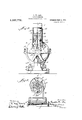
Figure 1 is a side elevation-of the complete apparatus: Fig. 2 shows an end view= as seen from the left of Figs-dand- 4;:p'a1'ts being broken away. Fig. fishows'a section" taken along the line 33 of F' 1. -Fig. 4'
showsn central vertical-longitu 1' sectionthrough the device.=along the line'- of Fig. 2. Fig. 5-is a detail showing the' means for relieving the" apparatus under exeessivei strains. Fig. 6 is a detail showing'the face of one'of the pulverizing diSllSflS seen from-'- fragmenta-l sectional view th h .t e other pulverizing disks, along the line 7of Fig.
machine which may =-be 'madeof a single casting having the bed plate 1, provided with the chamber 2 to which theniate'rial to be oundis fed, said chamber having an inclined bottom 3, and an "outlet 4. The" casting is also provided witha chamber 5 for the end thrust bearing 'on the shaft B.- This shaft'B carries the pulverizing disk C,
and is provided with a series of stepped and Fig. 3.2 shows shoulders 63 engaging the end-thrustbearings 7 inclosed-in the chamber 5. The/outer end of the shaftB carries-thedrive pulley *D provided with the cam pIateS-which gages. the roller 9' at the end of the bell crank -E. This bellcrank is pivoted to the 30 plate F which is mounted above-thecover The. upper arm 10 of 'the bell cranlr lever" is slotted'as at 11' to engagebetween the nuts 12 on thescrew bolt*13 iwhich i's' fastenedto the ="bot'toin of the reciprocating 0'6 chute H. 3 This chute-is supported by 'silient rods I4 and 15, the'rod"14 being connected to a yoke 16 sliding on the stanchions 17, whilethe rod 15 is connectedtd the plate-"- The disk M is m erablyliigreater than tha t of; the shaft B, for reasons which be The housing '1 is mounted;- on the .so. as to havens s'light longitudinal playy these links'being pivoted'td' the-housing at 19 men) the. base plate fit. as at: latter plate being adjustable; relative-to the 100 bed *plate'l to which it is attached-"The housing P is adjustably connected to -the main frameAb means of theheav'y screw'S which engages in the screw threads 21 in the main frame and passes through-the lug '22 on the housing P, whichlu'g is heldbetwee'n the lock nut 23 and .the: i rangible,- relieving device T. The latter -eonsi sts of three F. 'I. 'represents the lioppei which is idper- 2- The materialfis fedfik so "ted madman-J" which is providedwvith'h seriesof Ste 3B the section *line 6-6 of Fig; 4 and looking in the direction of thearrows.- 71is awashers mounted on the screw S, as shown in Fig. 4, details of which washers are shown more clearly in Fig. 5.
24 and 25 represent two end washers each having dull knife edges 26 ada ted to engage in corresponding grooves 2 and 28 in the plain washer 29. Lock nuts 30 hold the end washer 25 in place. It will be noted that the thrust on the shaft N is taken up by the bolt S, and when this thrust becomes excessive, the knife edges 26 will rupture the washer 29, allowing the housing P and with it, the shaft N and diskM, to slide backward a small distance. The link connection permits this backward and downward .movement of the said shaft N and housing P, and it is preferable to a straight sliding movement for the reason that appara tus of this character is apt to get clogged up with rust, or dirt, or other foreign matter, and to stick when the critical moment arrives, thus preventing the proper action of any automatic relieving attachments.
The chambers 5, and 5 are partly filled with oil through suitable oil inlets 31. The
surplus oil is carried away from the chamber 5 through passages 32 and 33. It is especially' desirableto prevent oil from getting into the ground products in the chamber 2, and for t is reason the oil from the chamber 5 is carried oil through the passage 33, and
-the oil from the chamber 5? that creeps under the shaft N toward the said chamber 2, fallsv into the annular trough 34 in the housing P, and escapes through an opening 35. (See Fig. 4) Oil, ducts36 may also be provided wherever desired.
The details of construction of the pulver ized disks are shown in Fig. 4 and in Figs. 6 to 12, which will now be described. The grinding portions of the two disks C and M are substantially identical in construction,
except that the two disks are preferably of unequal length axiallyfor reasons hereinafter to be explained. Each disk comprises an outer ring 41 having a radial flange 42 inside of which ring, and bearing endwise against said flange, is a series of wedge shaped blocks 43 and 44 made of soft and hard metal, such as soft iron and hard steel, alternately disposed- Inside of this circle of alternating hard and soft blocks, is another circle of blocks 45 and 46, separated by spacers 47, said spacers being provided with grooves 48 and end lugs 49, and being wedge shaped, as shown in Figs. 7 and 10. The blocks 45 are not as long axially as the blocks 46, and thus between the blocks 46 that the pockets in one disk are, of course,
deeper than those in the other. The disks are adapted to be attached either to the spider "U shown in Figs. 4 and 6, or to the disk V shown in Figs. 4tand 7. Thismay be conveniently done by means of tap. bolts 50. (See Fig.4) The disk V being imperfora'te, forms an end closure for the central chamber in the disk M, while the spider U with its. curved spokes 51 permits the material to be ground to pass into the chamber in the disk C, between said spokes, and to be thrown outward by centrifugal action into the pockets on the inner periphery of the two'pulverizing disks. The abutting faces of these two disks are preferably set to the desired distance apart, which would ordina- -rily,be extremely small.
In order to prevent circular scoring in the face of either disk, the axes of the shafts B and N are preferably eccentric. The two shafts are preferably caused to rotate in the same direction, the shaft N at' a much higher rate of speed than the shaft B, 'so that the centrifugal motion will always keep the in the pockets by the crushing blocks 46,'and
the smaller particles passing into the narrow space between the two disks will be ground by the hard pulverizing blocks 43.. The soft blocks 44 wlll wear away faster than the hard blocks causing little pockets to form between the hard blocks into which-pockets the larger particles of dust pass and are grolpnd under the grinding action of the two is s.
.The operation .of the device is as follows :The material to be ound being in the hopper I, the parts belng in'the position shown in Fig. 4 and the shafts B and N being in rotation, the cam plate 8 will rock the bell crank lever E vlbrating the chute H and shaking the material into the funnel K, whence it will pass through the throat K and into the chamber of the disk C, passing between the spokesin said chamher. The material will also enter the chamber of the disk M. The large particles will be crushed up ,in the pockets between the crushing blocks 46, and the finer particles will be thrown, by centrifugal force and also by gravity, into the space between the two disks, andwill drop down into the outlet 4, to be thence carried away in any convenient manner. .If any forelgn matter such as a nail, spike, or the like should et into the space between the rapidly rotating disks and tend to do serious injury to the machine, the thrust backward on the shaft N will cause the knife edges 26 to break the washer 29, and thus give immediate relief to the apparatus, for the cause of the injury would be so small that it would drop through the enlarged aperture between the disks; or the charge, then in the appai in place and the apparatus adjusted as before. 1
The disks C and M are preferably made of'different axial lengths for the following reasons :Suppose the blocks 46 in the disk C to be three inches in axial length, and
the similar blocks in the disk M to be five inches in axial length, and assume that the blocks must be at least 'oneinch long to be efiicient. The grinding faces will wear at substantially the same rate of speed, and in due course of time one of the disks will have ground down to the effective length of one inch, and the other disk to the effective length of threeinches. The appa ratus, of course, is to beset up from time to time to compensate for this wear. Now, when these disks have ground down as stated, it will be a simple matter-to take off and throw away the thin disk or stump andto shift the thick disk from the sup port V-to the spider U, and then put on a new disk having an effective length of five inches, attached tot-he support V. In this way, eighty per cent. of the'efi'ective wearing surface of the manufactured disks may be used up and far greater economy may be secured than if each disk were originally made of the same axial length. It will be noted that the space between the crushing surfaces is constantly changing, causing a squeezing and crushing e ct instead of solely a rubbing and grinding effect, there- "by reducing the material to the desired size without crushing a great portion to a much less or undesirable size.
Another advantage is that in a machine of this character, any desired maximum size of the resulting particles may be producedwithout the use of screens. ;In practice, I
prefer to run the slow speed disk at just about sufficient velocity to throw the particles outward and upward a ainst the action of gravity, and I have ound that about :one hundred and thirty revolutions per minute are about sufiicient for this purpose. The high speed crushing disk is preferably run at a much higher velocity. I have found in practice six hundred and thirty revolutions per-minute to be satisfac 'tory. This gives a crushing speed of five hundred revolutions per minute,- and with this arrangement of speeds of the two disks, the force of gravity is never sufiicient to cause the ore or other material being crushed: to run to thecenter of the disk or.
to fall back into the machine.
Itwill be obvious that other automatic speed attachments may be provided if desired and that other means for feeding the 55 apparatusmay be provided; also that various modifications might be made in the hereinafter described arrangement and combination of parts, which can be used without departing from' the spirit of my invention. Thus for instance, the two disks may be run in opposite directions, instead of in the same direction. The grinding blocks 47 should preferably be of harder material than the Wedge shaped spacing blocks 46., I
Having thus described my invention, what-I claim and desire to secure by Letters Patentof the United States is:
1. In an apparatus of the character described, the combination with oppositely disposed annular rotary disks, each disk being provided with a flanged ring, a series of pulverizer blocks mounted radially inside said ring, and a series of grinding blocks mounted inside ofsaid pulverizing blocks, with chambered spacing'blocks separating said grinding blocks, the whole forming a centrally chambered disk, with means for holding the faces of said disks in juxtaposition, and means for driving said disks, substantially as described.
2. In an apparatus of the character-described, the combination with oppositely disposed annular rotary disks, each disk being provided with a flanged ring, a series of pulverizer blocks of alternately hard and soft metal mounted radially inside said ring, and a series of grinding blocksmounted inside of said pulverizing blocks, with chambered spacing blocks separating said grinding blocks. the whole forming a contrally chambereddisk, with means for holding the faces of said disks. in juxtaposition, and means for driving said disks, in the same direction and at varying speeds, substantially as described.
3. In an apparatus of the character described, the combination with oppositely disposed annular rotary disks, each disk being provided with a flanged ring, a series of pulverizer blocks mounted radially inside of said ring, and a %ries of grinding blocks mounted inside of said pulverizing blocks, said grinding blocks being of unequal radial length, with chambered spacing blocks separating said grinding blocks, the whole forming a centrally chambered disk, means for holding the faces of-said disks in juxtaposition, and means for driving said disks, substantially as described.
4. In an apparatus of the character described, the' combination with oppositely disposed annular rotary disks, each disk I being provided with a flanged ring, a series of pulverizer blocks of alternately hard and soft metal mounted radially inside said ring, and a series of grinding blocks mounted inside radially of said pulverizing blocks, said grinding blocks being of unequal radial length, with chambered spacing blocks separating said grinding blocks, the whole 5. In an apparatus of the character described, the combination with oppositely disposed annular rotary disks, each disk being provided with a flanged ring, a series of pulverizer blocks of alternately hard and soft metal mounted radially inside said ring,
and a series of grinding blocks of unequal radial length mounted inside of said 'pul-' verizing blocks with wedge-shaped spacing blocks having end lugs and grooves separating said grinding blocks .the whole forming a centrally chambered disk, with means for holding the faces of said disks in juxtaposition, and means for driving said disks in the same direction and at different speeds, substantially as described.
6. An apparatus of the character described, comprising a main frame, and two oppositely disposed, annular, rotary disks mounted thereon, means for feeding the material to be ground to said disks, means for holding said disks in juxtaposition, comprising a housing, links supporting said housing, a screw bolt connecting said main frame and said housing, a shaft for one of said disks journaled in said housing, and means for releasing said housing and allowing it to swing backward on said links, when the pressure becomes excessive, said means comprising a frangible washer mounted on said screw bolt and other washers, having knife edges located on each side of the first mentioned washer and adapted to break same when the pressure becomes excessive, substantially as described.
7. An apparatus of the character described, comprising a main frame. and two oppositely disposed, annular, rotary disks mounted thereon, means for feeding the material to be ground to said disks, means for holding said disks-in juxtaposition, comprising a housing, links supporting said housing, a screw bolt connecting said main frame and said housing, a shaft for one of said disks journaled in said housing, and means for releasing said housing and allowing it to swing backward on said links, when the pressure becomes excessive, substantially as described.
8. In an apparatus of the character described, the combination comprising oppositely disposed annular rotary disks, forming together a central grinding chamber, each disk being provided with a flanged ring, a series of pulverizer blocks mounted radially inside said ring, and a series of grinding blocks mounted inside of said pulverizing blocks, with chambered spacing blocks separating said grinding blocks, substantially as described.
9. In an apparatus of the'character described, the combination comprising oppositely disposed annular rotary disks, forming together a central grinding chamber each disk being provided with a flanged ring, a series of pulverizer blocks of alternately hard and soft metal mounted radially inside said ring, and a series of grinding blocks mounted inside of said pulverizing blocks, with chambered spacing blocks separating'said grinding blocks, substantially as described.
10. In an apparatus of the character described, the combination comprising oppositely disposedannular rotary disks, forming together a central grinding chamber, each disk being provided with a flanged ring, a series of pulverizer blocks mounted radially inside of said ring, and a series of grinding blocks mounted inside of said pulverizing blocks, said grinding blocks being of unequal radial length, with chambered spacing blocks separating said grinding blocks, substantially as described.
11. In an apparatus of the character described, the combination comprising oppositely disposed annular rotary disks, forming together a central grinding chamber each disk being provided with a flanged ring, a series of pulverizer blocks of alternately hard and soft metal mounted radially inside said ring, and a series of grinding blocks mounted inside radially of said pulverizing blocks, said grinding blocks being of unequalradial length, with cham' bered spacing blocks separating said grinding blocks, substantially as described.
12. In an apparatus of the character described, the combination comprising oppositely disposed annular rotary disks, forming together a central grinding chamber each disk being provided with a flanged ring, a series of pulverizer blocks of alternately hard and soft metal mounted radially inside said ring, and a series of grinding blocks of unequal radial length mounted inside of said pulverizing blocks with wedge-shaped spacing blocks having end lugs and grooves separating said grinding blocks, substantially as described.
13. In an apparatus of the character described, the combination of rotary grinding disks forming together a central grinding chamber and comprising flanged rings, an outer annular series of alternately hard and soft pulverizing blocks mounted radially within each ring, and an annular series of crushing blocks and grooved spacing blocks tween the latter, and means for feeding material to said grinding disks.
14. In an apparatus of the character described, the combination of rotary grinding disks comprising flanged rings, an outer annular series of alternately hard and soft pulverizing blocks mounted radially within each ring, an annular series of crushing blocks and grooved spacing blocks mounted within said series of pulverizing blocks, said spacing blocks having a less radial dimension than said crushing blocks to provide arc-shaped, grooved pockets between the latter, end flanges extending radially from said spacing blocks flush with the inner faces of said crushing blocks, and means for feeding matprial to said grinding disks.
15. In an apparatus of the character described, the combination of rotary grinding disks comprising flanged rings, an outer annular series of alternately hard and soft pulverizing blocks mounted radially Within each ring, and an annular series of crushing blocks and grooved spacing blocks mounted within said series of pulverizing blocks, said spacing blocks having a less radial dimension than said crushing blocks to provide an inner peripheral series of arc-shaped, grooved pockets between the latter, and means for feeding material axially within said peripheral series of pockets.
I 16. In an apparatus of the character described, the combination of rotary grinding disks forming together a central grinding chamber and comprising flanged rings, an outer annular series of alternately hard and soft pulverizing blocks mounted radially within each ring, and an annular series of crushing blocks and grooved spacing blocks mounted within said series of pulverizing blocks, said spacing blocks having a less radial dimension than said crushing blocks to provide an inner peripheral series of arcshaped, grooved pockets between the latter, means for feeding material axially within said peripheral series of pockets, and means for rotating said grinding disks in the same direction at different speeds;
17. In an apparatus of the character described, the combination of rotary grinding disks, a bolt for holding said disks in cooperative relation, and a series of spaced washers provided with interengaging reduced bearing-surfaces slidably confined on said bolt.
18. In an apparatus of the character described, the combination of rotary grinding I disks, an adjust-ably mounted step bearing for one of said disks, a bolt, a medial disk slidably mounted on said bolt-and provided with perpendicular radial grooves onwits respective faces, a pair of end disks slidably mounted on said bolt and provided with bearing surfaces for engaging such grooves, and a nut threaded on said boltfor confining said engaged series of disks against said step bearing.
In testimony whereof, I aflix my signature, in presence of two witnesses.
FRANKLIN M. I-LER. Witnesses:
' R M. ANoREsoN, C, C. LEMM.
Priority Applications (1)
| Application Number | Priority Date | Filing Date | Title |
|---|---|---|---|
| US59551610A US1037772A (en) | 1910-12-03 | 1910-12-03 | Disk pulverizer. |
Applications Claiming Priority (1)
| Application Number | Priority Date | Filing Date | Title |
|---|---|---|---|
| US59551610A US1037772A (en) | 1910-12-03 | 1910-12-03 | Disk pulverizer. |
Publications (1)
| Publication Number | Publication Date |
|---|---|
| US1037772A true US1037772A (en) | 1912-09-03 |
Family
ID=3106049
Family Applications (1)
| Application Number | Title | Priority Date | Filing Date |
|---|---|---|---|
| US59551610A Expired - Lifetime US1037772A (en) | 1910-12-03 | 1910-12-03 | Disk pulverizer. |
Country Status (1)
| Country | Link |
|---|---|
| US (1) | US1037772A (en) |
-
1910
- 1910-12-03 US US59551610A patent/US1037772A/en not_active Expired - Lifetime
Similar Documents
| Publication | Publication Date | Title |
|---|---|---|
| US2509920A (en) | Feeding device for gyratory crushers | |
| US2357843A (en) | Rock breaker | |
| US2919864A (en) | Centrifugal pulverizer | |
| US2456266A (en) | Drum grinding mill with discharge openings in the liner | |
| US1338845A (en) | Wet-coal mill | |
| US1876416A (en) | Grinding mill | |
| US2555171A (en) | Material reduction mill | |
| US2575380A (en) | Crusher mill | |
| US2132508A (en) | Cone crusher | |
| US1648747A (en) | Pulverizer | |
| US2192606A (en) | Impact crusher | |
| US1683627A (en) | Pulverizing machine | |
| US1693247A (en) | Ring mill | |
| US1235030A (en) | Disintegrating-machine. | |
| US133455A (en) | Improvement in corn and cob mills | |
| US797616A (en) | Rotary breaker. | |
| US272233A (en) | gates | |
| US1171747A (en) | Pulverizer. | |
| US1363990A (en) | Ore-grinding machine | |
| US826711A (en) | Grinding-mill. | |
| US736657A (en) | Grinding-mill. | |
| US655745A (en) | Cylindrical roller-crusher. | |
| US1796104A (en) | Oil mill | |
| US513197A (en) | Henry james ralph pamphiloisr | |
| US3469795A (en) | Material reduction mill |