US103730A - Improved machine for making nails - Google Patents
Improved machine for making nails Download PDFInfo
- Publication number
- US103730A US103730A US103730DA US103730A US 103730 A US103730 A US 103730A US 103730D A US103730D A US 103730DA US 103730 A US103730 A US 103730A
- Authority
- US
- United States
- Prior art keywords
- feeders
- plates
- cutters
- series
- cutter
- Prior art date
- Legal status (The legal status is an assumption and is not a legal conclusion. Google has not performed a legal analysis and makes no representation as to the accuracy of the status listed.)
- Expired - Lifetime
Links
- 230000033001 locomotion Effects 0.000 description 5
- 238000010276 construction Methods 0.000 description 4
- 239000004020 conductor Substances 0.000 description 2
- 238000004519 manufacturing process Methods 0.000 description 2
- 230000009471 action Effects 0.000 description 1
- 230000008859 change Effects 0.000 description 1
- 230000000994 depressogenic effect Effects 0.000 description 1
- 230000007246 mechanism Effects 0.000 description 1
- 230000004048 modification Effects 0.000 description 1
- 238000012986 modification Methods 0.000 description 1
- 230000010355 oscillation Effects 0.000 description 1
- 230000001105 regulatory effect Effects 0.000 description 1
- 229940102098 revolution Drugs 0.000 description 1
Images
Classifications
-
- B—PERFORMING OPERATIONS; TRANSPORTING
- B21—MECHANICAL METAL-WORKING WITHOUT ESSENTIALLY REMOVING MATERIAL; PUNCHING METAL
- B21G—MAKING NEEDLES, PINS OR NAILS OF METAL
- B21G3/00—Making pins, nails, or the like
- B21G3/18—Making pins, nails, or the like by operations not restricted to one of the groups B21G3/12 - B21G3/16
- B21G3/26—Making pins, nails, or the like by operations not restricted to one of the groups B21G3/12 - B21G3/16 by cutting from strip or sheet material
Definitions
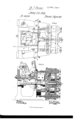
- Figure 1 is a plan view.
- Figure 2 a vertical longitudinal section in the planes indicated by the line z z, fig. 1.
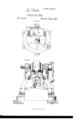
- Figure 3 a vertical-transverse section on the line y y, iig. 1, looking in the direction of the arrows 1.
- the cutter-table and head A A', griper B, and header C of my improved machine maybe of any preferred form, Vand arranged and actuated in' any proper manner.
- a frame, D of suitable form and dimensions, supports these and the other parts of the machine.
- the cutter-head A may receive its motion and power from such shaft through lever-arms et', pitmen F, and crank-wrists e, and the griper B through an arm, b, and cam. e'. e
- the header C is connected, through a shaft, c, a
- v 4 Arranged in front of the cutter-table A is atravelsing-table, H, provided with a series of feeders, I, and adapted, by its actuation, to present said feeders successively in proper position before the cutters.
- the table H, a's represented, is mounted on an axial shaft, 71 which, extending longitudinally through the machine, is provided at its inner end with a tight ratchet-wheel, h', and a loose cogged disk, J, the lat ter carrying a gravitating or-springpawl, j, engaging with said ratchet-wheel h', through which devices, in connection with a cogged segment, K, meshing with. the disk J, and a connecting-rod, L, or their equivalents, an intermittent rotary motion is imparted to said table from a crank, e", on the driving-shaft G.
- the feeders I being arranged in a concentric annular series in the table H, at equal distances apart,
- the feeders or conductors I are hollow, and their cavities are provided, on opposite sides, with straight longitudinal grooves, t, (represented by dotted lines in iigs. 1 4and 3,) for the guidance of the plates, which are advanced through the medium of stems t', by springs M, or their equivalents; said springs may radiate, as shown, and be secured by a central washer,
- An annular spring, N arranged within the circular series of feeders, and pressing outward against flat surfaces t" on each, corresponding with their respective faces, may form a brake or yielding' stop to hold the same in the positions to which they are moved.
- I further provide the frame with a segmental an ge, I, concentric with the table H, and in such proximity thereto, and of such relative radius, as for the flat points t ⁇ of the feeders I to pass so closely to it as to preclude turning, a gapfp, corresponding with the segment VO, permitting their being turned by the pro' vided ineans,'and an annular disk/or iiange, Q, parallel with the table, and behind said ange P, to limit the projection of the plates, the same losing its continuity at the cutters, and terminating in extensions q, adjustable by slots q', or their equivalent, to accommoflate different len'gths of cutters.
- the plates are supported by the stop Q and its extensions, q, until they arrive at the cntters,.when they are projected against the stop a on the cutter-head A'.
- the plates are brought back against the gauge R by a spring, S, attached tothe frame, and engaging with pins hm on the inner face of the table H. On the positive motion of the table being resumed, said spring is overcome, and the pins carried past it.
- the feeders are prevcntcdfrombeing carried. beyond the rangeV of the spring S, by the momentum -of the table, by a stop, c", projecting from the'face of the cutting-head A', and occupying, in the depressed position of said head, a recess in the cutter-table A.
- a jaw, T arranged in front of the cutter-head A', and pivoted conccntrically therewith, or otherwise, and actuated, at the proper moment, through a leverarm, t, and a cam, c, or their equivalents, serves to l hold the plates down on the stationary cutter, preparatory to and while they are being cut from.
- the nipper U by which the nails are caught as severed and presented to the griper, I compose of an upright rod, of suitable form, supported vertically by a spring, V, to enable it to give way to the cuttinghead. It is connected, by a stem, u, occupying a corresponding socket in a rock-shaft, XV, to said rockshaft, and is actuated through said rock-shaft, a lever-arm, w, thereof, and a cani surface, 6", on the driving-shaft, or their equivalents.
- the machine is intended to cut tapering blanks, andmay have either suitably-shaped cutters or a properly-arranged table for this purpose.
- the feeders I may be made in any desired ⁇ number of parts.
- the improved construction of the nipper enables a effectiveness.
- nail-plate feeders I, the pinions'i', and rack O for the purpose stated.
- the annular spring N In combination with the series of feeders ⁇ I, having -at surfaces i i,- and arranged in annular series in a rotating-table, H, and adapted to be reversed as described, the annular spring N, arranged within the series, as set forth for the purpose shown.
Landscapes
- Engineering & Computer Science (AREA)
- Mechanical Engineering (AREA)
- Crushing And Pulverization Processes (AREA)
Description
duim Citttrt peut i aus.
DAVID J. FARMER., OF WHEELING, WEST YIRGINIA.
Letters Patent No. 103,730, dated May 31, 1870.
IMPRovED MACHINE PoR MAKING NAILs.
The Schedule referred to in these Letters Patent: and making part of the same a. plate-feeding device,vof a traversing table, provided Y with a series of feeders proper, and so arranged and actuated as to present a number of plates successively, in proper manner, to the cutters, as hereinafter explained. l
Also, in a novel combination and arrangement of parts for holding and turning the plates in a feeder of this description. Also, in the provision of a novel combination and arrangement of stops and gauges for regulating and determining the position of the plates under lthe cutter.
Also, in the provision of a device, of novel construction, to hold'the nail-plates while they are being cut,
Also, in a superior construct-ion of nipper for catching the nail-blanks as they are severed from the plate.
-The several parts of my invention are applicable to machines having one or a plurality of cutters.
i Description of lrmciaq.Y
-The accompanying drawing represents a single-cutter machine, illustrating my invention.
Figure 1 is a plan view.
Figure 2, a vertical longitudinal section in the planes indicated by the line z z, fig. 1.
Figure 3, a vertical-transverse section on the line y y, iig. 1, looking in the direction of the arrows 1.
Figure 4, a vertical transverse section on the line y y, tig. 1, looking in the direction of the arrows 2.-
Similar letters of reference indicate like parts in the several gures.
General Description.
The cutter-table and head A A', griper B, and header C of my improved machine maybe of any preferred form, Vand arranged and actuated in' any proper manner.
A frame, D, of suitable form and dimensions, supports these and the other parts of the machine.
In the arrangement represented in the drawing, a. single driving-shaft, E, mounted in the upper rear extremity of the frame, imparts proper motiouto the. several moving parts.
The cutter-head A may receive its motion and power from such shaft through lever-arms et', pitmen F, and crank-wrists e, and the griper B through an arm, b, and cam. e'. e
The header C is connected, through a shaft, c, a
it, and screw, l
To enable the feeders to turn or reverse the plates,
lever-arm, c', and a ytogglelinlr,'(1r, with the cutterhead A', ata point on the back of the same, and thus receives its mot-ion therefrom. v 4 Arranged in front of the cutter-table A is atravelsing-table, H, provided with a series of feeders, I, and adapted, by its actuation, to present said feeders successively in proper position before the cutters.
The table H, a's represented, is mounted on an axial shaft, 71which, extending longitudinally through the machine, is provided at its inner end with a tight ratchet-wheel, h', and a loose cogged disk, J, the lat ter carrying a gravitating or-springpawl, j, engaging with said ratchet-wheel h', through which devices, in connection with a cogged segment, K, meshing with. the disk J, and a connecting-rod, L, or their equivalents, an intermittent rotary motion is imparted to said table from a crank, e", on the driving-shaft G.
The feeders I, being arranged in a concentric annular series in the table H, at equal distances apart,
the teeth of the ratchet-wheel It corresponding in number therewith, and the parts properly adjusted, at each revolution of the driving-shaft, one of said feeders will be .brought before the cutters in proper position.
The feeders or conductors I are hollow, and their cavities are provided, on opposite sides, with straight longitudinal grooves, t, (represented by dotted lines in iigs. 1 4and 3,) for the guidance of the plates, which are advanced through the medium of stems t', by springs M, or their equivalents; said springs may radiate, as shown, and be secured by a central washer,
they are further severally adaptedto rotate on their axes, ashrcpresented, suitable means being provided to actuate and hold them.
For rotating the same, I provide .each with a pinion, t, and the fratne with a toothed segment, O, properly arranged, which latter, by said pinions engaging with it as they are carried past in the movement of the table, causes them to make a half revo lution, as required.
An annular spring, N, arranged within the circular series of feeders, and pressing outward against flat surfaces t" on each, corresponding with their respective faces, may form a brake or yielding' stop to hold the same in the positions to which they are moved.
I further provide the frame with a segmental an ge, I, concentric with the table H, and in such proximity thereto, and of such relative radius, as for the flat points t` of the feeders I to pass so closely to it as to preclude turning, a gapfp, corresponding with the segment VO, permitting their being turned by the pro' vided ineans,'and an annular disk/or iiange, Q, parallel with the table, and behind said ange P, to limit the projection of the plates, the same losing its continuity at the cutters, and terminating in extensions q, adjustable by slots q', or their equivalent, to accommoflate different len'gths of cutters.
The usual stop a on the cutting-head limits the iusertion of the plates thereunder.
The plates are supported by the stop Q and its extensions, q, until they arrive at the cntters,.when they are projected against the stop a on the cutter-head A'.
A gauge, R, on the side of the cutter from which the plates are advanced, adjustable on .pin r, and hinged at r', to permit the passage of the plates thereunder, determines the proper position of the plates under the cutter.
The plates are brought back against the gauge R by a spring, S, attached tothe frame, and engaging with pins hm on the inner face of the table H. On the positive motion of the table being resumed, said spring is overcome, and the pins carried past it.
The feeders are prevcntcdfrombeing carried. beyond the rangeV of the spring S, by the momentum -of the table, by a stop, c", projecting from the'face of the cutting-head A', and occupying, in the depressed position of said head, a recess in the cutter-table A.
A jaw, T, arranged in front of the cutter-head A', and pivoted conccntrically therewith, or otherwise, and actuated, at the proper moment, through a leverarm, t, and a cam, c, or their equivalents, serves to l hold the plates down on the stationary cutter, preparatory to and while they are being cut from.
The nipper U, by which the nails are caught as severed and presented to the griper, I compose of an upright rod, of suitable form, supported vertically by a spring, V, to enable it to give way to the cuttinghead. It is connected, by a stem, u, occupying a corresponding socket in a rock-shaft, XV, to said rockshaft, and is actuated through said rock-shaft, a lever-arm, w, thereof, and a cani surface, 6", on the driving-shaft, or their equivalents.
The machine is intended to cut tapering blanks, andmay have either suitably-shaped cutters or a properly-arranged table for this purpose.
l propose making the traversing-table H of any suitable form to adapt it to operate substantially as herein described'.
The feeders I may be made in any desired `number of parts.
Advantages. Among the advantages of my improved constructions, combinations, aud arrangements of parts may ,be named the following:
By the employment of the traversing-table, with its number of feeders, the use of a number of plates at the same time is permitted, thus greatly lessening the labor of feeding the machine` and adapting it to Work continuously.
" The devices 'for' turning the feeders are of superior simplicity, and insure proper action. I
f The arrangement of stops and gauges insures the registering of the plates with the cutters, and the production of perfect nails. The .plate-clamping dcvice further insures this.l v
The improved construction of the nipper enables a effectiveness.
With necessary modification in dimensions of parts, but without any change in the essential characteristics of the invention, the same may be applied to the manufacture of tacks as well as of nails.
Claims.
I claim as my invention- 1. The traversing-table and series of nail-plate feeders or conductors, in combination with the cutters and mechanism to feed' said nail-plates forward between said cutters, substantially in the manner set forth.
. nail-plate feeders I, the pinions'i', and rack O, for the purpose stated.
3. In combination with the series of feeders` I, having -at surfaces i i,- and arranged in annular series in a rotating-table, H, and adapted to be reversed as described, the annular spring N, arranged within the series, as set forth for the purpose shown.
4. The combination of the flange P with the traversing series of reversing feeders I, as and for the purpose set forth.
5. The combination of the guard-flange or stop Q, and adjustable extensions q, with the traversing series of feeders I, for the purpose'shown.
6. The combination ofthe hinged gauge It with the traversing-table, series of feeders I, and a suitable detravwith the gauge cad lA', in
oscillation through a rock-shaft, WV, and lever-arm, w, substantial] y as shown and described.
DAVID J. FARMER Witnesses Y J AMES M. Piras, JOHN I. FARMER.
more positive movement and, consequently, increased v2. In combination with thetabie H, the series of vice for temporarily reversing the motion of said table,
neath the cutters, and adapted to receive a positixeV
Publications (1)
| Publication Number | Publication Date |
|---|---|
| US103730A true US103730A (en) | 1870-05-31 |
Family
ID=2173215
Family Applications (1)
| Application Number | Title | Priority Date | Filing Date |
|---|---|---|---|
| US103730D Expired - Lifetime US103730A (en) | Improved machine for making nails |
Country Status (1)
| Country | Link |
|---|---|
| US (1) | US103730A (en) |
-
0
- US US103730D patent/US103730A/en not_active Expired - Lifetime
Similar Documents
| Publication | Publication Date | Title |
|---|---|---|
| US103730A (en) | Improved machine for making nails | |
| US865001A (en) | Handle-making machine. | |
| US438712A (en) | painter | |
| US196869A (en) | Imp rove me nt in cut-nail machines | |
| US207444A (en) | Improvement in machines for forging horseshoe-nails | |
| US515393A (en) | Box-nailing machine | |
| US355117A (en) | Boot and shoe nailing machine | |
| US282107A (en) | nugent | |
| US309255A (en) | Wire nail machine | |
| US475768A (en) | houghton | |
| US72505A (en) | Jo si ah kirbt | |
| US1107337A (en) | Tack-supplying mechanism. | |
| US246933A (en) | worsley | |
| US241413A (en) | paere | |
| US8687A (en) | Nail-plate feedeb | |
| US170002A (en) | Improvement in nail-plate feeders | |
| US375302A (en) | Machine for making cut nails | |
| US48798A (en) | Machine for making horseshoe-nails | |
| US120117A (en) | Improvement in hub-mortising machines | |
| US413937A (en) | hansen | |
| US74094A (en) | Cyrus d | |
| US118355A (en) | Improvement in cut-nail machines | |
| US587029A (en) | abbott | |
| US496389A (en) | Wire-nail machine | |
| US62829A (en) | Improvement in machines foe outtino the eolls of window blinds |