US10360656B2 - Image displaying system and image displaying method applied thereto - Google Patents
Image displaying system and image displaying method applied thereto Download PDFInfo
- Publication number
- US10360656B2 US10360656B2 US15/791,894 US201715791894A US10360656B2 US 10360656 B2 US10360656 B2 US 10360656B2 US 201715791894 A US201715791894 A US 201715791894A US 10360656 B2 US10360656 B2 US 10360656B2
- Authority
- US
- United States
- Prior art keywords
- image
- adjusted
- display area
- setting information
- image displaying
- Prior art date
- Legal status (The legal status is an assumption and is not a legal conclusion. Google has not performed a legal analysis and makes no representation as to the accuracy of the status listed.)
- Active, expires
Links
- 238000000034 method Methods 0.000 title claims abstract description 44
- 239000004973 liquid crystal related substance Substances 0.000 claims abstract description 51
- 230000004044 response Effects 0.000 claims abstract description 12
- 230000002688 persistence Effects 0.000 claims abstract description 11
- 230000015654 memory Effects 0.000 claims description 17
- 239000000470 constituent Substances 0.000 claims description 11
- 238000012545 processing Methods 0.000 claims description 9
- 230000008569 process Effects 0.000 claims description 3
- 238000005516 engineering process Methods 0.000 abstract description 17
- 230000014759 maintenance of location Effects 0.000 abstract description 4
- 238000013459 approach Methods 0.000 description 7
- 230000015572 biosynthetic process Effects 0.000 description 5
- 230000008859 change Effects 0.000 description 3
- 230000006870 function Effects 0.000 description 3
- 238000010586 diagram Methods 0.000 description 2
- 239000000463 material Substances 0.000 description 2
- 238000012986 modification Methods 0.000 description 2
- 230000004048 modification Effects 0.000 description 2
- 238000012544 monitoring process Methods 0.000 description 2
- 230000000717 retained effect Effects 0.000 description 2
- 238000009825 accumulation Methods 0.000 description 1
- 238000005352 clarification Methods 0.000 description 1
- 230000000593 degrading effect Effects 0.000 description 1
- 238000011161 development Methods 0.000 description 1
- 238000007599 discharging Methods 0.000 description 1
- 238000001914 filtration Methods 0.000 description 1
- 230000006872 improvement Effects 0.000 description 1
- 238000004519 manufacturing process Methods 0.000 description 1
- 230000002633 protecting effect Effects 0.000 description 1
- 230000005236 sound signal Effects 0.000 description 1
- 238000002834 transmittance Methods 0.000 description 1
Images


Classifications
-
- G—PHYSICS
- G06—COMPUTING; CALCULATING OR COUNTING
- G06T—IMAGE DATA PROCESSING OR GENERATION, IN GENERAL
- G06T3/00—Geometric image transformations in the plane of the image
- G06T3/20—Linear translation of whole images or parts thereof, e.g. panning
-
- G—PHYSICS
- G09—EDUCATION; CRYPTOGRAPHY; DISPLAY; ADVERTISING; SEALS
- G09G—ARRANGEMENTS OR CIRCUITS FOR CONTROL OF INDICATING DEVICES USING STATIC MEANS TO PRESENT VARIABLE INFORMATION
- G09G3/00—Control arrangements or circuits, of interest only in connection with visual indicators other than cathode-ray tubes
- G09G3/20—Control arrangements or circuits, of interest only in connection with visual indicators other than cathode-ray tubes for presentation of an assembly of a number of characters, e.g. a page, by composing the assembly by combination of individual elements arranged in a matrix no fixed position being assigned to or needed to be assigned to the individual characters or partial characters
- G09G3/34—Control arrangements or circuits, of interest only in connection with visual indicators other than cathode-ray tubes for presentation of an assembly of a number of characters, e.g. a page, by composing the assembly by combination of individual elements arranged in a matrix no fixed position being assigned to or needed to be assigned to the individual characters or partial characters by control of light from an independent source
- G09G3/36—Control arrangements or circuits, of interest only in connection with visual indicators other than cathode-ray tubes for presentation of an assembly of a number of characters, e.g. a page, by composing the assembly by combination of individual elements arranged in a matrix no fixed position being assigned to or needed to be assigned to the individual characters or partial characters by control of light from an independent source using liquid crystals
-
- G—PHYSICS
- G02—OPTICS
- G02F—OPTICAL DEVICES OR ARRANGEMENTS FOR THE CONTROL OF LIGHT BY MODIFICATION OF THE OPTICAL PROPERTIES OF THE MEDIA OF THE ELEMENTS INVOLVED THEREIN; NON-LINEAR OPTICS; FREQUENCY-CHANGING OF LIGHT; OPTICAL LOGIC ELEMENTS; OPTICAL ANALOGUE/DIGITAL CONVERTERS
- G02F1/00—Devices or arrangements for the control of the intensity, colour, phase, polarisation or direction of light arriving from an independent light source, e.g. switching, gating or modulating; Non-linear optics
- G02F1/01—Devices or arrangements for the control of the intensity, colour, phase, polarisation or direction of light arriving from an independent light source, e.g. switching, gating or modulating; Non-linear optics for the control of the intensity, phase, polarisation or colour
- G02F1/13—Devices or arrangements for the control of the intensity, colour, phase, polarisation or direction of light arriving from an independent light source, e.g. switching, gating or modulating; Non-linear optics for the control of the intensity, phase, polarisation or colour based on liquid crystals, e.g. single liquid crystal display cells
- G02F1/133—Constructional arrangements; Operation of liquid crystal cells; Circuit arrangements
- G02F1/1333—Constructional arrangements; Manufacturing methods
- G02F1/13338—Input devices, e.g. touch panels
-
- G—PHYSICS
- G02—OPTICS
- G02F—OPTICAL DEVICES OR ARRANGEMENTS FOR THE CONTROL OF LIGHT BY MODIFICATION OF THE OPTICAL PROPERTIES OF THE MEDIA OF THE ELEMENTS INVOLVED THEREIN; NON-LINEAR OPTICS; FREQUENCY-CHANGING OF LIGHT; OPTICAL LOGIC ELEMENTS; OPTICAL ANALOGUE/DIGITAL CONVERTERS
- G02F1/00—Devices or arrangements for the control of the intensity, colour, phase, polarisation or direction of light arriving from an independent light source, e.g. switching, gating or modulating; Non-linear optics
- G02F1/01—Devices or arrangements for the control of the intensity, colour, phase, polarisation or direction of light arriving from an independent light source, e.g. switching, gating or modulating; Non-linear optics for the control of the intensity, phase, polarisation or colour
- G02F1/13—Devices or arrangements for the control of the intensity, colour, phase, polarisation or direction of light arriving from an independent light source, e.g. switching, gating or modulating; Non-linear optics for the control of the intensity, phase, polarisation or colour based on liquid crystals, e.g. single liquid crystal display cells
- G02F1/133—Constructional arrangements; Operation of liquid crystal cells; Circuit arrangements
- G02F1/1333—Constructional arrangements; Manufacturing methods
- G02F1/133397—Constructional arrangements; Manufacturing methods for suppressing after-image or image-sticking
-
- G02F2001/133397—
-
- G—PHYSICS
- G06—COMPUTING; CALCULATING OR COUNTING
- G06T—IMAGE DATA PROCESSING OR GENERATION, IN GENERAL
- G06T3/00—Geometric image transformations in the plane of the image
- G06T3/40—Scaling of whole images or parts thereof, e.g. expanding or contracting
-
- G—PHYSICS
- G09—EDUCATION; CRYPTOGRAPHY; DISPLAY; ADVERTISING; SEALS
- G09G—ARRANGEMENTS OR CIRCUITS FOR CONTROL OF INDICATING DEVICES USING STATIC MEANS TO PRESENT VARIABLE INFORMATION
- G09G2310/00—Command of the display device
- G09G2310/08—Details of timing specific for flat panels, other than clock recovery
-
- G—PHYSICS
- G09—EDUCATION; CRYPTOGRAPHY; DISPLAY; ADVERTISING; SEALS
- G09G—ARRANGEMENTS OR CIRCUITS FOR CONTROL OF INDICATING DEVICES USING STATIC MEANS TO PRESENT VARIABLE INFORMATION
- G09G2320/00—Control of display operating conditions
- G09G2320/02—Improving the quality of display appearance
- G09G2320/0204—Compensation of DC component across the pixels in flat panels
-
- G—PHYSICS
- G09—EDUCATION; CRYPTOGRAPHY; DISPLAY; ADVERTISING; SEALS
- G09G—ARRANGEMENTS OR CIRCUITS FOR CONTROL OF INDICATING DEVICES USING STATIC MEANS TO PRESENT VARIABLE INFORMATION
- G09G2320/00—Control of display operating conditions
- G09G2320/02—Improving the quality of display appearance
- G09G2320/0257—Reduction of after-image effects
-
- G—PHYSICS
- G09—EDUCATION; CRYPTOGRAPHY; DISPLAY; ADVERTISING; SEALS
- G09G—ARRANGEMENTS OR CIRCUITS FOR CONTROL OF INDICATING DEVICES USING STATIC MEANS TO PRESENT VARIABLE INFORMATION
- G09G2320/00—Control of display operating conditions
- G09G2320/04—Maintaining the quality of display appearance
- G09G2320/043—Preventing or counteracting the effects of ageing
- G09G2320/046—Dealing with screen burn-in prevention or compensation of the effects thereof
-
- G—PHYSICS
- G09—EDUCATION; CRYPTOGRAPHY; DISPLAY; ADVERTISING; SEALS
- G09G—ARRANGEMENTS OR CIRCUITS FOR CONTROL OF INDICATING DEVICES USING STATIC MEANS TO PRESENT VARIABLE INFORMATION
- G09G2320/00—Control of display operating conditions
- G09G2320/08—Arrangements within a display terminal for setting, manually or automatically, display parameters of the display terminal
-
- G—PHYSICS
- G09—EDUCATION; CRYPTOGRAPHY; DISPLAY; ADVERTISING; SEALS
- G09G—ARRANGEMENTS OR CIRCUITS FOR CONTROL OF INDICATING DEVICES USING STATIC MEANS TO PRESENT VARIABLE INFORMATION
- G09G2340/00—Aspects of display data processing
- G09G2340/04—Changes in size, position or resolution of an image
- G09G2340/0407—Resolution change, inclusive of the use of different resolutions for different screen areas
-
- G—PHYSICS
- G09—EDUCATION; CRYPTOGRAPHY; DISPLAY; ADVERTISING; SEALS
- G09G—ARRANGEMENTS OR CIRCUITS FOR CONTROL OF INDICATING DEVICES USING STATIC MEANS TO PRESENT VARIABLE INFORMATION
- G09G2340/00—Aspects of display data processing
- G09G2340/04—Changes in size, position or resolution of an image
- G09G2340/0464—Positioning
-
- G—PHYSICS
- G09—EDUCATION; CRYPTOGRAPHY; DISPLAY; ADVERTISING; SEALS
- G09G—ARRANGEMENTS OR CIRCUITS FOR CONTROL OF INDICATING DEVICES USING STATIC MEANS TO PRESENT VARIABLE INFORMATION
- G09G2354/00—Aspects of interface with display user
Definitions
- the present invention relates to an image displaying system and an image displaying method, and more particularly to a system and a method for solving an image sticking problem or an image retention phenomenon in an existing liquid crystal displaying technology.
- An image displaying device such as a general television or a general display device has been widely used. Recently, it is an important issue to improve the quality of the image frame in order to develop the image displaying technology. With increasing development of science and technology, the image displaying device is gradually developed from the early cathode ray tube display to the today's liquid crystal display (LCD).
- LCD liquid crystal display
- the basic image displaying quality is significantly improved and the overall volume of the image displaying device is reduced, the applications of the displaying technology are broadened.
- the LCD displaying technology still has some drawbacks.
- the liquid crystal molecule itself is not luminous. Consequently, the LCD display uses a backlights module (e.g., LED) as a light source and controls the liquid crystal arrangement of the liquid crystal panel to produce the illuminated image.
- a backlights module e.g., LED
- the liquid crystal panel is light-transmissible, and the liquid crystal molecules are arranged in an array.
- the combination of the brightness and the corresponding color exhibits the image contents (e.g., characters or symbols).
- the voltage applied to the polarizing plate is controlled, the polarity of the liquid crystal molecules is correspondingly changed. Consequently, the arrangement of the liquid crystal molecules is adjusted. Since the liquid crystal molecules are correspondingly rotated, the transmittance of the light beam from the backlight source is changed.
- the voltage between the two electrodes of the polarizing plate is subjected to a tiny change after the image shown on the LCD screen has been kept unchanged for a certain time period.
- the charges retained between the two electrodes result in the gradual accumulation of the voltage.
- the liquid crystal molecules are suffered from variation. Due to the variation, an image sticking problem occurs. For example, after the screen content is refreshed to generate a new frame, a portion of the old content of the original image frame is also shown on the screen.
- the image sticking problem is not generated.
- a specified image frame has to be shown on the screen for a long time.
- the industrial monitoring message, the news channel logo or the medical workstation bed message needs to be shown on the screen for a long time.
- the same image frame is not shown on the screen for a long time.
- the frame shown on the screen is automatically switched after a specified time interval. For example, a screen saver program is executed.
- the circuitry layer is designed to dynamically adjust the voltage or adjust the discharging time sequence in order to release the residual charges quickly.
- the manufacturing process and the material of the liquid crystal panel are improved.
- the associated applications still have some drawbacks.
- the image block to be maintained for a long time is possibly interfered by a meaningless frame.
- the improvement in the hardware component increases the fabricating and searching cost. Therefore, the conventional displaying technology needs to be further improved.
- the present invention provides an image displaying system and an image displaying method.
- the displayed content on the screen is changed in a very short time. Consequently, the image sticking problem or the image retention phenomenon in an existing liquid crystal displaying technology can be effectively overcome.
- the monitored image can be continuously retained on the screen.
- an image displaying method for an image displaying system includes a liquid crystal screen with a display area.
- the image displaying method includes the following steps. Firstly, the image displaying system receives an image signal. Consequently, an original frame corresponding to the image signal is shown on the display area at a first time point. Then, an adjusted image is shown on the display area at a second point according to a setting information. The adjusted image and the original frame have different contents. Then, the adjusted image is not shown but the original frame is shown on the display area at a third time point. The time difference between the third time point and the first time point is not larger than a response time period corresponding to the human persistence of vision.
- the image displaying method is performed.
- the image displaying system further includes a user interface and an electrically erasable programmable read-only memory.
- the image displaying method further includes steps of generating the setting information through the user interface and storing the setting information into the electrically erasable programmable read-only memory.
- the setting information contains a resolution setting information about the display area, a displaying setting information about the adjusted image and a constituent setting information about the adjusted image.
- the image displaying system further includes a dynamic random access memory
- the image displaying method further includes a step of storing the original frame into the dynamic random access memory
- the image displaying system further includes a database, and the adjusted image is composed of one or plural adjusted patterns, wherein the one or plural adjusted patterns are stored in the database so as to be accessed.
- each of the adjusted patterns corresponds to one or plural display units of the liquid crystal screen.
- the adjusted image is completely shown on the display area after the original image is replaced by the one or plural adjusted patterns, or the one or plural adjusted patterns and the original frame are combined together and simultaneously shown on the display area according to an on screen display setting.
- the plural adjusted patterns are sequentially shown on the display area along a predetermined displaying direction, or the one or plural adjusted patterns are randomly shown on the display area.
- the image displaying system further includes an image processor
- the image displaying method further includes the steps of accessing the corresponding adjusted patterns from the database, analyzing the adjusted patterns and processing the adjusted patterns according to the setting information, and combining the adjusted patterns as the adjusted image through an adjusting library after the adjusted patterns are processed.
- the original frame shown on the display area is processed by the image processor through an original library.
- an image displaying system includes a signal input terminal and a liquid crystal screen.
- the signal input terminal receives an image signal.
- the liquid crystal screen includes a display area.
- An original frame corresponding to the image signal is shown on the display area at a first time point.
- An adjusted image is shown on the display area at a second point according to a setting information.
- the adjusted image is not shown on display area but the original frame on the display area at a third time point.
- the adjusted image and the original frame have different contents.
- the time difference between the third time point and the first time point is not larger than a response time period corresponding to the human persistence of vision.
- the image displaying system further includes a user interface and an electrically erasable programmable read-only memory.
- the setting information is generated through the user interface.
- the setting information is stored in the electrically erasable programmable read-only memory.
- the setting information contains a resolution setting information about the display area, a displaying setting information about the adjusted image and a constituent setting information about the adjusted image.
- the image displaying system further includes a dynamic random access memory, and the original frame is stored in the dynamic random access memory.
- the image displaying system further includes a database, and the adjusted image is composed of one or plural adjusted patterns, wherein the one or plural adjusted patterns are stored in the database so as to be accessed.
- each of the adjusted patterns corresponds to one or plural display units of the liquid crystal screen.
- the adjusted image is completely shown on the display area after the original image is replaced by the one or plural adjusted patterns, or the one or plural adjusted patterns and the original frame are combined together and simultaneously shown on the display area according to an on screen display setting.
- the plural adjusted patterns are sequentially shown on the display area along a predetermined displaying direction, or the one or plural adjusted patterns are randomly shown on the display area.
- the image displaying system further includes an image processor.
- the image processor analyzes the corresponding adjusted patterns from the database, processes the adjusted patterns according to the setting information, and combines the adjusted patterns as the adjusted image through an adjusting library after the adjusted patterns are processed.
- the original frame shown on the display area is processed by the image processor through an original library.
- the present invention provides an image displaying system and an image displaying method.
- the contents shown on the liquid crystal screen are changed in a very short time. Since the liquid crystal molecules are rotated to release the accumulated voltage, the image sticking problem or the image retention phenomenon in the existing liquid crystal displaying technology is overcome.
- the technology of the present invention can provide good adjusting efficacy.
- the original frame can be normally monitored by the user without interference.
- the pattern with protection and declaration can be embedded in the screen in a very short time that is not perceived by the human eye.
- FIG. 1 is a schematic functional diagram illustrating an image displaying system according to a first embodiment of the present invention
- FIG. 2 is a flowchart illustrating an image displaying method for the image displaying device according to the first embodiment of the present invention
- FIGS. 3A, 3B and 3C schematically illustrate the consecutive frames shown on the display area of the liquid crystal screen in response to image adjustment according to the first embodiment of the present invention.
- FIG. 4 schematically illustrates the original frame and the adjusted image shown on the display area of the liquid crystal screen in response to image adjustment according to a second embodiment of the present invention.
- FIG. 1 is a schematic functional diagram illustrating an image displaying system according to a first embodiment of the present invention.
- the image displaying system 1 comprises a central processing unit 10 , a signal input terminal 14 , a liquid crystal screen 12 , an image processor 11 , a user interface 13 and a storage medium 15 .
- the signal input terminal 14 is used to receive an image signal P 1 .
- the image signal P 1 is an operational content signal from an industrial monitor or a workstation.
- the signal is an image signal, and the image signal is related to an image frame that is kept unchanged for a long time.
- the signal contains both of an image signal and an audio signal.
- the liquid crystal screen 12 comprises a display area 120 (see FIG. 3A ).
- the contents corresponding to the image signal P 1 are shown on the display area 120 .
- the user interface 13 the user may perform the operations and make associated settings to implement the image displaying method of the present invention.
- the user interface 13 is a remote controller or an operation panel that is installed in the monitor or the image displaying device.
- the remote controller or the operation panel comprises plural keys. Via the keys, the settings of different functions and operations can be made.
- the storage medium 15 has the function of storing and recording data.
- the storage medium 15 comprises a dynamic random access memory (DRAM) 151 , a flash memory 152 and an electrically erasable programmable read-only memory (EEPROM) 153 .
- DRAM dynamic random access memory
- EEPROM electrically erasable programmable read-only memory
- the image displaying method of the present invention is performed. While the image signal P 1 is outputted, the frame corresponding to the streaming data of the image signal P 1 (e.g., an original frame) is stored in the DRAM 151 .
- the above results set by the user are stored in the EEPROM 153 .
- the application program is a resident program. After the image displaying system 1 is booted, the application program starts to be executed. Consequently, the information associated with the settings is continuously stored in the storage medium. Even if the image displaying system 1 is powered off, the information associated with the settings does not disappear. Moreover, the execution of the application program allows the image signal P 1 to be normally outputted while performing the designated adjustment corresponding to the additional image processing operation.
- the central processing unit 10 is responsible for the accessing links, the signal processing operations and the signal receiving operations between all functional components.
- the storage medium 15 of the image displaying system 1 further comprises a database 154 .
- the memory of the database 154 is not restricted. For example, the memory of any of the above types is feasible.
- the data or pictures for image adjustment are stored into and accessible to the database 154 . Moreover, these data or pictures are set by the user through the user interface 13 according to the practical requirements.
- FIG. 2 is a flowchart illustrating an image displaying method for the image displaying system according to the first embodiment of the present invention.
- FIGS. 3A, 3B and 3C schematically illustrate the consecutive frames shown on the display area of the liquid crystal screen in response to image adjustment according to the first embodiment of the present invention.
- the image signal P 1 is received by the image displaying system, and an original frame A 1 corresponding to the image signal P 1 is shown on the display area 120 at a first time point (Step S 1 ).
- an adjusted image A 2 is shown on the display area 120 at a second point according to a setting information (Step S 2 ).
- the adjusted image A 2 and the original frame A 1 have different contents.
- the adjusted image A 2 is not shown on the display area 120 but the original frame A 1 is shown on the display area 120 at a third time point (Step S 3 ).
- the time difference between the third time point and the first time point is not larger than the response time period corresponding to the human persistence of vision.
- the image signal P 1 is continuously received by the signal input terminal 14 and sequentially and temporarily stored into the DRAM 151 .
- the original frame A 1 corresponding to the image signal P 1 is a frame whose content has been just refreshed.
- the original frame A 1 corresponding to the image signal P 1 is a frame whose content has not been refreshed for a long time. Since the technology of the present invention is used to solve the image sticking problem, the original frame A 1 is an image frame that has been kept unchanged for a long time period (e.g., 10 minutes) before the first time point.
- the image processor 11 analyzes whether the content of the original frame A 1 is kept unchanged. The analyzed result of the image processor 11 is helpful for the subsequent automatic judgment.
- the adjusted image A 2 is composed of plural adjusted patterns 20 .
- These adjusted patterns 20 have the same size.
- each adjusted pattern 20 corresponds to plural display units (not shown) of the liquid crystal screen 12 . That is, each adjusted pattern 20 is equivalent to plural display units that are representative of the resolution of the liquid crystal screen 12 .
- each display unit of the liquid crystal screen 12 is very small with respect to the human eye.
- the adjusted image A 2 should be specially designed.
- each adjusted pattern 20 is equivalent to plural display units of the liquid crystal screen 12 , and the content of each adjusted pattern 20 is different from the contents of the corresponding display units of the original frame A 1 .
- the gray levels are different. Consequently, all of the adjusted patterns 20 are uniformly distributed on the display area 120 . Under this circumstance, the liquid crystal molecules are subjected to a rotational change, and the accumulated voltage is released. Consequently, the image stick problem is solved.
- each adjusted pattern is equivalent to one display unit of the liquid crystal screen 12 . That is, the size of the adjusted pattern is equal to the size of the display unit of the liquid crystal screen 12 .
- the time period of completing the entire of the adjusted image A 2 is extended.
- the adjusted patterns of the adjusted image have different sizes.
- the entire of the adjusted image is substantially composed of one adjusted pattern. That is, the size of the adjusted pattern is equal to the size of the entire of the adjusted image and distributed in the whole display area 120 .
- the constituent and the displaying way of the original frame A 1 are completely replaced by those of the adjusted pattern of the adjusted image, and the adjusted pattern of the adjusted image is shown on the entire of the display area 120 .
- portions of the adjusted patterns 20 are shown on the display area 120 .
- the portions of the adjusted patterns 20 and the original frame A 1 are combined together and simultaneously shown on the display area 120 according to an on screen display (OSD) setting. That is, in the step S 2 , the display area 120 is not completely occupied by the adjusted image A 2 at the second time point and a portion of the original frame A 1 is still shown on the display area 120 .
- OSD on screen display
- the plural adjusted patterns 20 of the adjusted image A 2 are sequentially shown on the display area 120 along a predetermined displaying direction.
- the plural adjusted patterns 20 are sequentially shown on the display area 120 from the left side to the right side and from the top side to the bottom side.
- plural scan lines are horizontally scanned from the left side to the right side and vertically scanned from the top side to the bottom side. In such way, the adjusted image A 2 is produced.
- the formation of the adjusted image A 2 is related to the scanning speed.
- the second time point is the time point when the adjusted image A 2 is formed. In other words, the time point of starting to scan the adjusted image A 2 and the time point of forming the adjusted image A 2 are between the first time point and the second time point.
- the adjusted image A 2 is formed at a fast scanning speed that is not perceived by the human eye.
- the setting information contains the resolution setting information about the display area 120 (i.e., the displaying resolution information about the original frame A 1 ), the displaying setting information about the adjusted image A 2 , the constituent setting information about the adjusted image A 2 , an so on.
- the displaying setting about the adjusted image A 2 includes the on screen display (OSD) setting information, the sequential displaying information or the random displaying information, which will be described later.
- the constituent setting information about the adjusted image A 2 is the setting information about the adjusted patterns 20 .
- the user may set and generate the above setting information through the user interface 13 .
- the setting information may be stored in the EEPROM 153 .
- the adjusted image A 2 is shown according to the setting information.
- the method of displaying the adjusted image A 2 is controlled by the image processor 11 .
- the displaying method of the first embodiment comprises the following steps. Firstly, the central processing unit 10 accesses one or plural adjusted patterns 20 from the database 154 . Then, the image processor 11 analyzes the adjusted patterns 20 and processes the adjusted patterns 20 according to the setting information. For example, the image processing operation performed by the image processor 11 includes an image filtering operation, an image degrading operation, an analyzing operation, and so on. After the image processing operation is completed, the adjusted patterns 20 are combined as the adjusted image A 2 by an adjusting library.
- the adjusting library is a library for the on screen display (OSD) setting. Moreover, the adjusting library is a compile file that is executed by a specified program. According to the display specification of the corresponding hardware component (e.g., the liquid crystal screen 12 ), the analyzed and processed data are combined as the adjusted image A 2 by the adjusting library and shown on the hardware component.
- OSD on screen display
- the adjusting library is a compile file that is executed by a specified program. According to the display specification of the corresponding hardware component (e.g., the liquid crystal screen 12 ), the analyzed and processed data are combined as the adjusted image A 2 by the adjusting library and shown on the hardware component.
- one or plural adjusted patterns are stored in the database 154 .
- the adjusted patterns may have different contents (e.g., sizes or gray levels). Consequently, the adjusted patterns can be accessed and combined as the adjusted image A 2 .
- the contents of the adjusted image A 2 and the contents of the corresponding display units of the original frame A 1 e.g., the gray levels
- the suitable adjusted patterns 20 are placed on the display area by the adjusting library according to the contents of the corresponding display units of the original frame A 1 . In such way, the accumulated voltage between the two electrodes of the corresponding positions is released.
- the generation of the adjusted image A 2 can overcome the image sticking problem after the liquid crystal molecules are subjected to a rotational change.
- the time period of generating the adjusted image A 2 is not too long.
- the adjusted image A 2 is not shown on the display area 120 but the original frame A 1 is shown on the display area 120 at the third time point. That is, the situation of FIG. 3A is returned.
- the formation of the adjusted image A 2 is not perceived by the human eye.
- the time difference between the third time point and the first time point is very short. Particularly, the time difference between the third time point and the first time point is smaller than or equal to (i.e., not larger than) the response time period corresponding to the human persistence of vision. If the switching speed corresponding to the time difference between the third time point and the first time point is faster than the response speed corresponding to the human persistence of vision, the image displaying system 1 can overcome the image sticking problem.
- the formation of the adjusted image A 2 is not perceived by the user. Due to human persistence of vision, the original frame A 1 can be normally monitored by the user without interference. In other words, the image sticking problem can be effectively solved.
- portions of the adjusted patterns 20 and the original frame A 1 are simultaneously shown on the display area 120 according to an the screen display (OSD) setting.
- OSD screen display
- the image processor 11 is responsible for showing the original frame A 1 .
- an original library other than the adjusting library is responsible for showing the original frame A 1 on the display area 120 .
- the original frame A 1 and the adjusted image A 2 are obtained from different image sources.
- both of the original frame A 1 and the adjusted image A 2 are shown on the same display area 120 .
- the data are written into the same frame buffer. Since the image sources are different, the original library is responsible for showing the original frame A 1 on the display area 120 in the time interval from the first time point to the third time point.
- the steps S 2 and S 3 are repeatedly done. That is, after the original frame A 1 is shown again or the original frame A 1 has been refreshed for a long time, the similar adjusted image is shown again according to the setting.
- the way of showing the new adjusted image may be similar to that of the first embodiment.
- the way of showing the new adjusted image is different.
- the adjusted patterns are randomly shown on the display area to solve the image sticking problem.
- the first embodiment may be further modified.
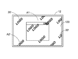
- FIG. 4 schematically illustrates the original frame and the adjusted image shown on the display area of the liquid crystal screen in response to image adjustment according to a second embodiment of the present invention.
- the hardware setting and the image displaying method of this embodiment are similar to those of the first embodiment.
- FIGS. 3A and 3C are similar to those of the first embodiment, and are not redundantly described herein.
- the way of showing the adjusted image A 2 ′ in this embodiment is distinguished.
- plural adjusted patterns 20 ′ are randomly shown on the display area 120 .
- FIG. 4 indicates the step S 2 of the image displaying method.
- the adjusted image A 2 ′ is composed of plural adjusted patterns 20 ′.
- the adjusted patterns 20 ′ have the same size and the same type.
- each adjusted pattern 20 ′ is a watermark or a trade mark. That is, the adjusted pattern 20 ′ contains the text content and the picture content.
- the adjusted patterns 20 ′ are previously stored in the database 154 by the user. Consequently, the adjusted patterns 20 ′ are accessible from the database 154 .
- the size of each adjusted pattern 20 ′ corresponds to plural display units of the liquid crystal screen 12 .
- the adjusted patterns are randomly shown.
- the distances between the adjacent adjusted patterns 20 ′ are not constant or these adjusted patterns 20 ′ are asymmetric.
- the positions of these adjusted patterns 20 ′ are determined by the adjusting library in a specified manner (e.g., according to a random number).
- the number of the adjusted patterns 20 ′ and the positions of the adjusted patterns 20 ′ may be randomly determined at each time.
- the adjusted image is possibly composed of one adjusted pattern.
- portions of the adjusted patterns 20 ′ of the adjusted image A 2 ′ and the original frame A 1 are combined together and simultaneously shown on the display area 120 according to a screen display (OSD) setting.
- OSD screen display
- the constituent contents of the adjusted image A 2 ′ i.e., the adjusted patterns 20 ′
- the contents of the corresponding display units of the original frame A 1 e.g., the gray levels
- the formation of the adjusted image A 2 ′ is not perceived by the user. Due to human persistence of vision, the original frame A 1 can be normally monitored by the user without interference. Moreover, in case that the adjusted pattern 20 ′ is the watermark or the trade mark, an additional special displaying function can be provided. For example, since the adjusted pattern 20 ′ is combined with the original frame A 1 in a very short time that is not perceived by the human eye, the efficacy of declaring confidentiality or right can be achieved. For example, if someone wants to use an image pickup device to shoot the content of the displayed frame, the adjusted image A 2 ′ can provides a protecting effect to prevent the entire of the important content to be captured. Moreover, the formation of the adjusted image A 2 ′ can help the user find out whether the image frame is stolen.
- the adjusted image is composed of plural different adjusted patterns and plural identical adjusted patterns, wherein the positions of the adjusted patterns are determined by the adjusted library. For example, some adjusted patterns contain the picture contents, but the other adjusted patterns contain the text contents only. These adjusted patterns are stored in the database 154 so as to be accessed. In case that the adjusted image is composed of plural different adjusted patterns, each adjusted pattern has to be stored in the database 154 .
- the steps S 2 and S 3 as shown in FIG. 2 can be repeatedly done. Since the adjusted patterns 20 ′ are randomly shown on the display area, the positions, the numbers or sizes of the adjusted patterns 20 ′ may be varied according to the practical requirements. Since all of the display units corresponding to the original frame A 1 are possibly adjusted, the efficacy of eliminating the image sticking problem is enhanced.
- the present invention provides an image displaying system and an image displaying method.
- the technology of the present invention can be used to solve the drawbacks of the conventional liquid crystal displaying technology. Especially when a specified image frame has to be shown on the screen for a long time, the technology of the present invention can provide good adjusting efficacy.
- the contents shown on the liquid crystal screen are changed in a very short time. Since the liquid crystal molecules are rotated to release the accumulated voltage, the image sticking problem is overcome. Moreover, since the adjusted pattern is embedded in the display area in a very short time that is not perceived by the human eye, the efficacy of declaring confidentiality or right can be achieved.
- the original frame can be normally monitored by the user without interference. Moreover, since the image displaying method of the present invention is implemented through execution of a software program, the cost associated with the hardware component is reduced. Moreover, in case that the image displaying method of the present invention is automatically implemented, the monitoring loading on the user is largely reduced. For example, after the original frame has been shown for ten minutes, the image displaying method of the present invention is automatically implemented.
- the present invention can effectively solve the drawbacks of the conventional technology while achieving the purposes of the present invention.
Landscapes
- Engineering & Computer Science (AREA)
- Physics & Mathematics (AREA)
- General Physics & Mathematics (AREA)
- Theoretical Computer Science (AREA)
- Chemical & Material Sciences (AREA)
- Crystallography & Structural Chemistry (AREA)
- Computer Hardware Design (AREA)
- Control Of Indicators Other Than Cathode Ray Tubes (AREA)
Abstract
Description
Claims (19)
Applications Claiming Priority (3)
| Application Number | Priority Date | Filing Date | Title |
|---|---|---|---|
| TW106126390A TWI634776B (en) | 2017-08-04 | 2017-08-04 | Image display system and image display method of the same |
| TW106126390 | 2017-08-04 | ||
| TW106126390A | 2017-08-04 |
Publications (2)
| Publication Number | Publication Date |
|---|---|
| US20190043163A1 US20190043163A1 (en) | 2019-02-07 |
| US10360656B2 true US10360656B2 (en) | 2019-07-23 |
Family
ID=60293685
Family Applications (1)
| Application Number | Title | Priority Date | Filing Date |
|---|---|---|---|
| US15/791,894 Active 2037-12-20 US10360656B2 (en) | 2017-08-04 | 2017-10-24 | Image displaying system and image displaying method applied thereto |
Country Status (3)
| Country | Link |
|---|---|
| US (1) | US10360656B2 (en) |
| EP (1) | EP3438962A1 (en) |
| TW (1) | TWI634776B (en) |
Families Citing this family (1)
| Publication number | Priority date | Publication date | Assignee | Title |
|---|---|---|---|---|
| US11842421B1 (en) | 2022-09-30 | 2023-12-12 | AUO Corporation | Method and display device for embedding watermark information to dimming signal of backlight module |
Citations (7)
| Publication number | Priority date | Publication date | Assignee | Title |
|---|---|---|---|---|
| US20030112259A1 (en) * | 2001-12-04 | 2003-06-19 | Fuji Photo Film Co., Ltd. | Method and apparatus for registering modification pattern of transmission image and method and apparatus for reproducing the same |
| US6959339B1 (en) * | 1998-11-06 | 2005-10-25 | International Business Machines Corporation | Technique for handling a universal image format on the internet |
| US20100053429A1 (en) * | 2008-08-26 | 2010-03-04 | Sony Corporation | Picture signal processing unit, image display unit, and picture signal processing method |
| US20100085477A1 (en) * | 2008-10-03 | 2010-04-08 | Hitachi Displays, Ltd. | Display device |
| US20110025910A1 (en) * | 2009-07-31 | 2011-02-03 | Sanyo Electric Co., Ltd. | Frame rate converter and display apparatus equipped therewith |
| US20160293089A1 (en) * | 2015-04-02 | 2016-10-06 | Asustek Computer Inc. | Display device and operation method thereof |
| US20180240100A1 (en) * | 2015-08-04 | 2018-08-23 | Skeyecode | Method for securing a transaction from a non-secure terminal |
Family Cites Families (5)
| Publication number | Priority date | Publication date | Assignee | Title |
|---|---|---|---|---|
| KR101217226B1 (en) * | 2006-01-27 | 2012-12-31 | 삼성전자주식회사 | Display device capable of reducing afterimage and afterimage reduction method thereof |
| TW201007682A (en) * | 2008-08-15 | 2010-02-16 | Ultrachip Inc | Black insertion method for liquid crystal display |
| TW201015509A (en) * | 2008-10-14 | 2010-04-16 | Acula Technology Corp | Display screen protection method and display driving apparatus |
| TWI488166B (en) * | 2008-10-21 | 2015-06-11 | Acer Inc | Method and system for reduce image sticking |
| CN103778897B (en) * | 2014-01-28 | 2016-03-02 | 北京京东方显示技术有限公司 | A kind of image display control method and device |
-
2017
- 2017-08-04 TW TW106126390A patent/TWI634776B/en active
- 2017-10-24 US US15/791,894 patent/US10360656B2/en active Active
- 2017-10-26 EP EP17001771.9A patent/EP3438962A1/en not_active Withdrawn
Patent Citations (7)
| Publication number | Priority date | Publication date | Assignee | Title |
|---|---|---|---|---|
| US6959339B1 (en) * | 1998-11-06 | 2005-10-25 | International Business Machines Corporation | Technique for handling a universal image format on the internet |
| US20030112259A1 (en) * | 2001-12-04 | 2003-06-19 | Fuji Photo Film Co., Ltd. | Method and apparatus for registering modification pattern of transmission image and method and apparatus for reproducing the same |
| US20100053429A1 (en) * | 2008-08-26 | 2010-03-04 | Sony Corporation | Picture signal processing unit, image display unit, and picture signal processing method |
| US20100085477A1 (en) * | 2008-10-03 | 2010-04-08 | Hitachi Displays, Ltd. | Display device |
| US20110025910A1 (en) * | 2009-07-31 | 2011-02-03 | Sanyo Electric Co., Ltd. | Frame rate converter and display apparatus equipped therewith |
| US20160293089A1 (en) * | 2015-04-02 | 2016-10-06 | Asustek Computer Inc. | Display device and operation method thereof |
| US20180240100A1 (en) * | 2015-08-04 | 2018-08-23 | Skeyecode | Method for securing a transaction from a non-secure terminal |
Also Published As
| Publication number | Publication date |
|---|---|
| TWI634776B (en) | 2018-09-01 |
| TW201911849A (en) | 2019-03-16 |
| US20190043163A1 (en) | 2019-02-07 |
| EP3438962A1 (en) | 2019-02-06 |
Similar Documents
| Publication | Publication Date | Title |
|---|---|---|
| US7864194B2 (en) | Systems and methods for motion adaptive filtering | |
| US8707191B2 (en) | Multi-screen synthesizing display apparatus and method | |
| US20170148422A1 (en) | Refresh control method and apparatus of display device | |
| US20120299970A1 (en) | Application of voltage to data lines during vcom toggling | |
| JP4408107B2 (en) | Liquid crystal display device and driving method thereof | |
| US20170353704A1 (en) | Environment-Aware Supervised HDR Tone Mapping | |
| US20170006337A1 (en) | Desktop display method and device, and smart television | |
| US10916206B2 (en) | Display apparatus and control method thereof | |
| US11812190B2 (en) | Interface access method, display apparatus and electronic device | |
| WO2019137097A1 (en) | Video displaying method, video displaying apparatus, and computer-program product | |
| US10360656B2 (en) | Image displaying system and image displaying method applied thereto | |
| US8204610B2 (en) | Eletronic device, display device, and method of controlling audio/video output of an electronic device | |
| WO2021015853A1 (en) | Adaptive low power touch and display device | |
| CN108597435B (en) | Method for controlling display of display panel, device thereof and display device | |
| US7880702B2 (en) | Picture display apparatus | |
| US10475368B2 (en) | Display device and method for controlling the same | |
| KR20100058757A (en) | Display device having afterimage protection and control method thereof | |
| CN111126168B (en) | Display screen and electronic equipment | |
| KR20040063567A (en) | Method for preventing image sticking on a image display device using pdp module | |
| US11335279B2 (en) | Display optimization method and a display apparatus | |
| US7091942B2 (en) | Electrooptic device and driving method thereof | |
| KR20160067275A (en) | Display device and method of driving a display device | |
| CN109391835A (en) | Image display system and the image display method being applied thereon | |
| JP2020183997A (en) | Screen display program, device and method | |
| CN115278027B (en) | Display control method and device |
Legal Events
| Date | Code | Title | Description |
|---|---|---|---|
| AS | Assignment |
Owner name: FLYTECH TECHNOLOGY CO., LTD, TAIWAN Free format text: ASSIGNMENT OF ASSIGNORS INTEREST;ASSIGNORS:LIU, YUN-PING;LIU, CHIH-YUAN;REEL/FRAME:043936/0623 Effective date: 20171023 |
|
| FEPP | Fee payment procedure |
Free format text: ENTITY STATUS SET TO UNDISCOUNTED (ORIGINAL EVENT CODE: BIG.); ENTITY STATUS OF PATENT OWNER: SMALL ENTITY |
|
| FEPP | Fee payment procedure |
Free format text: ENTITY STATUS SET TO SMALL (ORIGINAL EVENT CODE: SMAL); ENTITY STATUS OF PATENT OWNER: SMALL ENTITY |
|
| STPP | Information on status: patent application and granting procedure in general |
Free format text: NON FINAL ACTION MAILED |
|
| STPP | Information on status: patent application and granting procedure in general |
Free format text: RESPONSE TO NON-FINAL OFFICE ACTION ENTERED AND FORWARDED TO EXAMINER |
|
| STPP | Information on status: patent application and granting procedure in general |
Free format text: PUBLICATIONS -- ISSUE FEE PAYMENT VERIFIED |
|
| STCF | Information on status: patent grant |
Free format text: PATENTED CASE |
|
| MAFP | Maintenance fee payment |
Free format text: PAYMENT OF MAINTENANCE FEE, 4TH YR, SMALL ENTITY (ORIGINAL EVENT CODE: M2551); ENTITY STATUS OF PATENT OWNER: SMALL ENTITY Year of fee payment: 4 |