US10349837B2 - Materials and methods for non-invasively measuring temperature distribution in the eye - Google Patents
Materials and methods for non-invasively measuring temperature distribution in the eye Download PDFInfo
- Publication number
- US10349837B2 US10349837B2 US15/863,389 US201815863389A US10349837B2 US 10349837 B2 US10349837 B2 US 10349837B2 US 201815863389 A US201815863389 A US 201815863389A US 10349837 B2 US10349837 B2 US 10349837B2
- Authority
- US
- United States
- Prior art keywords
- light beam
- laser
- area
- speckle
- eye
- Prior art date
- Legal status (The legal status is an assumption and is not a legal conclusion. Google has not performed a legal analysis and makes no representation as to the accuracy of the status listed.)
- Active
Links
- 238000000034 method Methods 0.000 title claims abstract description 42
- 239000000463 material Substances 0.000 title description 5
- 210000001525 retina Anatomy 0.000 claims description 35
- 238000003384 imaging method Methods 0.000 claims description 26
- 241000282414 Homo sapiens Species 0.000 claims description 9
- 238000012545 processing Methods 0.000 claims description 7
- 238000005286 illumination Methods 0.000 claims description 6
- 230000001427 coherent effect Effects 0.000 description 11
- 239000002184 metal Substances 0.000 description 11
- 229910052751 metal Inorganic materials 0.000 description 11
- 230000002207 retinal effect Effects 0.000 description 8
- 238000009529 body temperature measurement Methods 0.000 description 4
- 206010064930 age-related macular degeneration Diseases 0.000 description 3
- 230000001419 dependent effect Effects 0.000 description 3
- 239000000835 fiber Substances 0.000 description 3
- 239000004615 ingredient Substances 0.000 description 2
- 230000010354 integration Effects 0.000 description 2
- 208000002780 macular degeneration Diseases 0.000 description 2
- 238000005259 measurement Methods 0.000 description 2
- 239000000203 mixture Substances 0.000 description 2
- 210000005166 vasculature Anatomy 0.000 description 2
- 241000283690 Bos taurus Species 0.000 description 1
- 239000004593 Epoxy Substances 0.000 description 1
- 241000282326 Felis catus Species 0.000 description 1
- 208000008069 Geographic Atrophy Diseases 0.000 description 1
- 241000282412 Homo Species 0.000 description 1
- 241000124008 Mammalia Species 0.000 description 1
- 241001465754 Metazoa Species 0.000 description 1
- 208000022873 Ocular disease Diseases 0.000 description 1
- 206010057430 Retinal injury Diseases 0.000 description 1
- 238000004458 analytical method Methods 0.000 description 1
- 238000013459 approach Methods 0.000 description 1
- 238000004364 calculation method Methods 0.000 description 1
- 238000003745 diagnosis Methods 0.000 description 1
- 238000002405 diagnostic procedure Methods 0.000 description 1
- 230000003292 diminished effect Effects 0.000 description 1
- 230000000694 effects Effects 0.000 description 1
- 230000005670 electromagnetic radiation Effects 0.000 description 1
- 238000005516 engineering process Methods 0.000 description 1
- 238000002474 experimental method Methods 0.000 description 1
- 230000005283 ground state Effects 0.000 description 1
- 230000002427 irreversible effect Effects 0.000 description 1
- 238000002955 isolation Methods 0.000 description 1
- 238000012986 modification Methods 0.000 description 1
- 230000004048 modification Effects 0.000 description 1
- 238000012544 monitoring process Methods 0.000 description 1
- 230000008397 ocular pathology Effects 0.000 description 1
- 230000003287 optical effect Effects 0.000 description 1
- 230000001991 pathophysiological effect Effects 0.000 description 1
- BBKDWPHJZANJGB-IKJXHCRLSA-N quizalofop-P-tefuryl Chemical compound O=C([C@H](OC=1C=CC(OC=2N=C3C=CC(Cl)=CC3=NC=2)=CC=1)C)OCC1CCCO1 BBKDWPHJZANJGB-IKJXHCRLSA-N 0.000 description 1
- 230000004256 retinal image Effects 0.000 description 1
- 239000004065 semiconductor Substances 0.000 description 1
- 238000000926 separation method Methods 0.000 description 1
- 238000012360 testing method Methods 0.000 description 1
Images


Classifications
-
- A—HUMAN NECESSITIES
- A61—MEDICAL OR VETERINARY SCIENCE; HYGIENE
- A61B—DIAGNOSIS; SURGERY; IDENTIFICATION
- A61B5/00—Measuring for diagnostic purposes; Identification of persons
- A61B5/01—Measuring temperature of body parts ; Diagnostic temperature sensing, e.g. for malignant or inflamed tissue
-
- A—HUMAN NECESSITIES
- A61—MEDICAL OR VETERINARY SCIENCE; HYGIENE
- A61B—DIAGNOSIS; SURGERY; IDENTIFICATION
- A61B3/00—Apparatus for testing the eyes; Instruments for examining the eyes
- A61B3/0016—Operational features thereof
- A61B3/0025—Operational features thereof characterised by electronic signal processing, e.g. eye models
-
- A—HUMAN NECESSITIES
- A61—MEDICAL OR VETERINARY SCIENCE; HYGIENE
- A61B—DIAGNOSIS; SURGERY; IDENTIFICATION
- A61B3/00—Apparatus for testing the eyes; Instruments for examining the eyes
- A61B3/10—Objective types, i.e. instruments for examining the eyes independent of the patients' perceptions or reactions
- A61B3/14—Arrangements specially adapted for eye photography
-
- G—PHYSICS
- G01—MEASURING; TESTING
- G01K—MEASURING TEMPERATURE; MEASURING QUANTITY OF HEAT; THERMALLY-SENSITIVE ELEMENTS NOT OTHERWISE PROVIDED FOR
- G01K11/00—Measuring temperature based upon physical or chemical changes not covered by groups G01K3/00, G01K5/00, G01K7/00 or G01K9/00
-
- G—PHYSICS
- G01—MEASURING; TESTING
- G01K—MEASURING TEMPERATURE; MEASURING QUANTITY OF HEAT; THERMALLY-SENSITIVE ELEMENTS NOT OTHERWISE PROVIDED FOR
- G01K13/00—Thermometers specially adapted for specific purposes
-
- G01K13/002—
-
- G—PHYSICS
- G01—MEASURING; TESTING
- G01K—MEASURING TEMPERATURE; MEASURING QUANTITY OF HEAT; THERMALLY-SENSITIVE ELEMENTS NOT OTHERWISE PROVIDED FOR
- G01K13/00—Thermometers specially adapted for specific purposes
- G01K13/20—Clinical contact thermometers for use with humans or animals
-
- G—PHYSICS
- G01—MEASURING; TESTING
- G01N—INVESTIGATING OR ANALYSING MATERIALS BY DETERMINING THEIR CHEMICAL OR PHYSICAL PROPERTIES
- G01N21/00—Investigating or analysing materials by the use of optical means, i.e. using sub-millimetre waves, infrared, visible or ultraviolet light
- G01N21/17—Systems in which incident light is modified in accordance with the properties of the material investigated
- G01N21/47—Scattering, i.e. diffuse reflection
- G01N21/4788—Diffraction
-
- A—HUMAN NECESSITIES
- A61—MEDICAL OR VETERINARY SCIENCE; HYGIENE
- A61B—DIAGNOSIS; SURGERY; IDENTIFICATION
- A61B5/00—Measuring for diagnostic purposes; Identification of persons
- A61B5/0059—Measuring for diagnostic purposes; Identification of persons using light, e.g. diagnosis by transillumination, diascopy, fluorescence
- A61B5/0062—Arrangements for scanning
-
- G—PHYSICS
- G01—MEASURING; TESTING
- G01K—MEASURING TEMPERATURE; MEASURING QUANTITY OF HEAT; THERMALLY-SENSITIVE ELEMENTS NOT OTHERWISE PROVIDED FOR
- G01K2213/00—Temperature mapping
-
- G—PHYSICS
- G01—MEASURING; TESTING
- G01N—INVESTIGATING OR ANALYSING MATERIALS BY DETERMINING THEIR CHEMICAL OR PHYSICAL PROPERTIES
- G01N21/00—Investigating or analysing materials by the use of optical means, i.e. using sub-millimetre waves, infrared, visible or ultraviolet light
- G01N21/17—Systems in which incident light is modified in accordance with the properties of the material investigated
- G01N21/47—Scattering, i.e. diffuse reflection
- G01N21/4788—Diffraction
- G01N2021/479—Speckle
Definitions
- Sources such as the sun or lasers used in clinical settings can induce changes in temperature in the eye.
- the retina can suffer irreversible damages if exposed to heat out of physiological range (>37° C.).
- Current retinal temperature measurement modalities for animals are limited to invasive techniques. However, such invasive techniques cannot be generally utilized to measure the temperature distribution of the eye.
- the present invention provides devices and methods for measuring the temperature distribution of an eye, particularly, the retina, using non-invasive techniques.
- the devices and methods can be used, for example, to assess the pathophysiological rate of ambient light-induced retinal temperature elevation.
- the present invention utilizes laser speckle cross-correlation techniques.
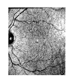
- FIG. 1A is an original retina fundus image showing the vasculature of a healthy volunteer.
- FIG. 1B is a filtered version of the retina image of FIG. 1A showing the vasculature of a healthy volunteer.
- FIG. 1C is a realized phantom of FIG. 1A on an absorbing and scattering epoxy layer (divisions on the right hand side are in mm).
- FIG. 2 is an image of a speckle imaging system according to an embodiment of the present invention.
- FIG. 3 is a graph of correlation coefficients versus time, showing speckle cross-correlation with a temperature dependent model.
- FIG. 4 shows modeling heat distribution in the eye. Heat spots in eye can influence the temperature in other areas. A localized change in retinal temperature induced an asymmetric temperature distribution in the eye. External temperature measurement (FLIR) cannot be used to determine retinal temperature differences.
- FLIR External temperature measurement
- FIG. 5 provides an embodiment of the laser speckle imaging system.
- the LSI system's coherent light source illuminates the metallic rod's surface.
- the light source produces a speckle pattern on the rod and a stack of images of the speckle pattern are acquired using software (Matlab, Natick, Mass.). Any change of the material property, due to heat, will decrease the speckle autocorrelation.
- FIG. 6 provides a close-up view of sample with laser beam.
- White arrow and paper corner denote start of vertical separation between insulated and non-insulated parts of rod.
- FIG. 7 shows insulated and not insulated areas of the metal rod. Isolation (electrical tape) is placed beneath rod before imaging.
- FIG. 8 shows pixel cross-correlation. Pixel cross-correlation was calculated on each frame of the image stack over time.
- FIG. 9 shows effects of temperature on cross-correlation plots. As the temperature increases from 30° C. to 42° C., an exponential decay occurs in both cross-correlation plots.
- the non-insulated rod shows faster decorrelation than the insulated rod.
- FIG. 10A shows raw speckle image showing insulated [left] and non-insulated [right].
- FIG. 10B shows cross correlation of image stack sselling the difference in fitting parameter between both sides.
- the non-insulated side shows faster decorrelation.
- FIG. 11 shows schematic representation of an exemplary laser speckle imaging system of the invention that could be used to determine temperature of a portion of the retina or of the entire retina.
- the present invention provides devices and methods for measuring the temperature distribution of an eye of a subject using non-invasive techniques.
- the method of the invention measures the temperature distribution of the retina.
- the determination of the temperature distribution can be used in the diagnosis, and/or monitoring the progression of, an ocular pathology.
- a confirmatory diagnostic procedure can also be performed.
- treatment for the ocular disorder can be administered.
- the subject is a mammal, such as, for example, a human, a dog, a cat, cattle, or a horse.
- nonexudative age-related macular degeneration can be caused by changes in eye temperature.
- diagnostic prediction of age related macular degeneration can be readily provided accurately and quickly by, for example, an ophthalmologist.
- the basic method for determining retinal temperature is to observe speckle contrast created by a coherent light source.
- a rough surface a surface with RMS surface height variation that is large with respect to the laser light wavelength
- Any change in the material properties of the surface, including a change in temperature, will decrease speckle cross-correlation.
- This approach can be used to measure the temperature at specific locations (X, Y) throughout the retina.
- a first speckle pattern originating from a portion of the retina can be obtained by projecting a first beam onto the portion of the retina.
- a speckle size of at least 5 ⁇ 5 pixels is preferred.
- the speckle pattern is dependent on local optical properties and temperature and can have a wavelength of about 700 nm, in a range from 600 nm to 800 nm, or more specifically in a range from 650 nm to 750 nm (with a power that is preferably at or below 1 mWatt).
- the speckle pattern can then be altered by applying a short pulse of a second laser onto the portion of the retina while the first beam is continuously illuminating the portion of the retina.
- the second beam can have a wavelength of about 633 nm, or a range from 575 nm to 675 nm, or more specifically a range from 600 nm to 650 nm (with a power that is preferably at or below 1 mWatt).
- a second speckle pattern originating from the portion of the retina resulting from the first beam after the pulse of the second beam is then obtained. Speckle cross-correlation between the first speckle pattern and the second speckle pattern is then measured, and the temperature decay after the pulse second laser can be used to measure the temperature of the portion of the retina.
- the first and the second beams are scanned through different locations in the retina to measure temperatures in multiple locations in the retina. For example, beams can be scanned throughout the entire retina to determine the temperatures throughout the entire retina.
- Another embodiment of the present invention includes applying two or more laser pulses onto the retina as the second beams.
- the first beam and the second beam can have different energy levels.
- the first beam can have twice the energy of the second beam, and then the ground temperature of the retina can be measured.
- the laser can be aligned co-axially with the speckle illumination.
- a speckle fundus imager can be fabricated to obtain real time imagery of the retina including temperature data.
- Embodiments of the present invention can incorporate the use of laser speckle cross-correlation technology. Speckle based techniques can be used to measure very subtle changes in the index of refraction within a medium.
- Data acquisition can be done by, for example, illuminating a retina with a coherent light (or electromagnetic radiation) source and imaging the retina with a CCD camera. This exploits the relationship between camera integration time and speckle lifetime. If the speckle lifetime is short compared to integration time, the contrast will be diminished. Furthermore, calculation of localized speckle contrast allows for the determination of speckle lifetime and velocity, which is inversely related to speckle lifetime.
- a speckle-based imaging system can include a camera, an imaging system, and computer software and hardware that analyze the data captured by the imaging system.
- certain embodiments of the invention provide a method for measuring a temperature of an area, comprising:
- step c) receiving a second speckle pattern produced by the first light beam from the area after illuminating the area with the second light beam in step c),
- step f measuring the temperature of the area based on the pixel cross-correlation determined in step e).
- step d) of receiving the second speckle pattern is performed between about 0.5 milliseconds (msec) to about 5 msec after step b), preferably, after about 0.75 msec to about 3 msec after step b), more preferably, between about 1 msec to 2 msec after step b), and even more preferably, about 1 msec after step b).
- step c) can be performed for about 0.5 milliseconds (msec) to about 5 msec, preferably, for between about 0.75 msec to about 3 msec, more preferably, for between about 1 msec to 2 msec, and even more preferably, for about 1 msec.
- the methods of the invention are used to determine the temperature of a surface in an eye of a subject, particularly, a human eye. Therefore, certain embodiments of the invention provide a method for measuring a temperature of an area in an eye, comprising the steps a) to f) described above.
- the first light beam and the second light beam can have different energies.
- the first light beam has twice the energy compared to the second light beam.
- each of the first light beam and the second light beam has the energy of less than 1 mWatt.
- the first light beam and the second light beam can also have different wavelengths.
- the first light beam can have a wavelength between 600 nm to 800 nm, particularly, 650 nm to 750 nm, and more particularly, about 700 nm.
- the second light beam can have a wavelength between 600 nm to 650 nm, particularly, about 625 nm, and more particularly, about 633 nm.
- the first and/or the second light beam can have a diameter of 0.5 mm and the first and/or the second light beam lasts for 1 about millisecond.
- the first light beam has a large diameter encompassing the whole retina.
- the speckle pattern includes many speckles with each speckle at least 3 ⁇ 3 pixels, preferably, 5 ⁇ 5 pixels.
- the first and second speckle patterns have 3 ⁇ 3 to 7 ⁇ 7 pixels, preferably, 4 ⁇ 4 to 8 ⁇ 8 pixels, more preferably, 5 ⁇ 5 to 7 ⁇ 7 pixels, and even more preferably, 5 ⁇ 5 pixels or 6 ⁇ 6 pixels.
- the method of determining a temperature of a surface within an eye according to the invention can be extrapolated to determine the temperature distribution in an eye, particularly, in a human eye.
- the invention provides a method for determining a temperature distribution in an eye, comprising:
- the area is continuously illuminated with the first light beam throughout sub-steps i) to iv) of step a).
- the area is illuminated with both the first beam and the second beam and in sub-step iv), the area is only illuminated with the first beam.
- step iv) of receiving the second speckle pattern is performed between about 0.5 msec to about 5 msec after step ii), preferably, after about 0.75 msec to about 3 msec after step ii), more preferably, between about 1 msec to 2 msec after step ii), and even more preferably, about 1 msec after step ii).
- step iii) can be performed for about 0.5 milliseconds (msec) to about 5 msec, preferably, for between about 0.75 msec to about 3 msec, more preferably, for between about 1 msec to 2 msec, and even more preferably, for about 1 msec.
- the invention provides a laser speckle imaging system, comprising a coherent light source, a camera, and a polarized single mode fiber.
- the coherent light source can be a laser diode.
- the laser diode can emit a light having a wavelength between 600 to 800 nm, particularly, about 625 nm, 650 nm, 675 nm, 700 nm, 725 nm, 750 nm, 775 nm, or 800 nm.
- the camera can comprise a polarizer and a lens, particularly, a 50 mm fl, F#1.3 lens. Lenses can be incorporated into the imaging system to filter and magnify light coming from the eye or retina. For optimal results, a resolution of up to, or greater than, 5, 6, 7, 8, or 9 ⁇ m/pixel is preferred.
- the laser speckle imaging system comprises a first laser that provides a first laser beam to an area to be illuminated, a second laser that provides the pulse second laser beam, a Galvanometer mirror, which optionally in conjunction with a dichroic, deflects the pulse second laser beam to the area.
- the area to be illuminated is on a plate.
- the area to be illuminated is a subject's retina.
- the laser speckle imaging system is designed so that a subject can be positioned in a manner that the first and the second laser beams can be projected onto the subject's retina.
- the laser speckle imaging system can further comprise a processing apparatus.
- a processing apparatus comprises a microprocessor, storage, bus system, and at least one user interface element, optionally with user input.
- the user interface element can be chosen from a display, a keyboard, and a mouse.
- the system comprises at least one integrated circuit and/or at least one semiconductor.
- the processing apparatus receives from the camera the data corresponding to: a first light speckle pattern produced by a first illumination of a surface by a first light beam emitted by the coherent light source and a second light speckle pattern produced by a second illumination of the surface by a second light beam emitted by the coherent light source.
- the processing apparatus compares the first light speckle pattern with the second light speckle pattern and provides the temperature of the surface.
- Acquisition and analysis software can be custom fabricated using a variety of commercially available tools (e.g., Matlab, Natick, Mass.).
- the laser speckle imaging system of the coherent light source is configured to illuminate a surface of an eye.
- the camera is configured to receive light speckle pattern from the surface of the eye.
- Such laser speckle imaging system can be used to determine temperature of an area within an eye of a subject, particularly, a human eye.
- the laser speckle imaging system of the invention configured to illuminate and image a surface of an eye can be used to determining a temperature of an area in an eye.
- Such method comprises:
- step c) receiving a second speckle pattern produced by the first light beam from the area after illuminating the area with the second light beam in step c),
- step f measuring the temperature of the area based on the pixel cross-correlation determined in step e).
- the area is continuously illuminated with the first light beam throughout steps a) to d). In such embodiments, during step c), the area is illuminated with both the first beam and the second beam and in step d), the area is only illuminated with the first beam.
- step d) of receiving the second speckle pattern is performed between about 0.5 msec to about 5 msec after step b), preferably, after about 0.75 msec to about 3 msec after step b), more preferably, between about 1 msec to 2 msec after step b), and even more preferably, about 1 msec after step b).
- step c) can be performed for about 0.5 milliseconds (msec) to about 5 msec, preferably, for between about 0.75 msec to about 3 msec, more preferably, for between about 1 msec to 2 msec, and even more preferably, for about 1 msec.
- the first light beam and the second light beam have different energies.
- the first light beam has twice the energy compared to the second light beam.
- each of the first light beam and the second light beam has the energy of less than 1 mWatt, for example, below 0.9, 0.8, 0.7, 0.6, or 0.5 mWatt.
- the first light beam and the second light beam can also have different wavelengths.
- the first light beam can have a wavelength between 600 nm to 800 nm, particularly, 650 nm to 750 nm, and more particularly, about 700 nm.
- the second light beam can have a wavelength between 600 nm to 650 nm, particularly, about 625 nm, and more particularly, about 633 nm.
- the first and/or the second light beam can have a diameter of 0.5 mm and the first and/or the second light beam lasts for 1 about millisecond.
- the first and second speckle patterns have 3 ⁇ 3 to 7 ⁇ 7 pixels, preferably, 4 ⁇ 4 to 8 ⁇ 8 pixels, more preferably, 5 ⁇ 5 to 7 ⁇ 7 pixels, and even more preferably, 5 ⁇ 5 pixels or 6 ⁇ 6 pixels.
- FIGS. 2 and 5 An example of using the laser speckle imaging system to capture retinal images is described in FIGS. 2 and 5 .
- Examples of retinal phantoms captured using an embodiment of the present invention is represented in FIG. 1 .
- ranges are stated in shorthand, to avoid having to set out at length and describe each and every value within the range. Any appropriate value within the range can be selected, where appropriate, as the upper value, lower value, or the terminus of the range.
- a range of 0.1-1.0 represents the terminal values of 0.1 and 1.0, as well as the intermediate values of 0.2, 0.3, 0.4, 0.5, 0.6, 0.7, 0.8, 0.9, and all intermediate ranges encompassed within 0.1-1.0, such as 0.2-0.5, 0.2-0.8, and 0.7-1.0.
- pixel cross-correlation between a first speckle pattern and a second speckle pattern represents the difference in speckle patterns. Such differences include differences in the pixel locations, pixel intensity, pixel number, etc.
- a laser speckle imaging system was constructed to measure the temperature of retinal phantoms, as shown in FIG. 1 .
- the system can be seen in the image of FIG. 2 .
- the system included a 12-bit, monochrome camera (Pantera® TF 1M60, Dalsa, Ontario, Canada) with 1024 ⁇ 1024 resolution, and maximum frame rate of 60 Hz.
- a 50 mm focal length F#1.3 lens (Precise Optics, Bay Shore N.Y.) was used with the camera for magnification and to obtain resolutions of up to 7 ⁇ m/pixel.
- the light source was a 640 nm, 200 mW diode laser (Melles Griot, Longmont, Colo.), connected to a single mode fiber.
- the laser acted as a coherent light source and the camera was used to observe speckle contrast. Based on the speckle contrast measurements, the temperature at specific locations (X, Y) throughout the retina was determined. A speckle size of at least 5 ⁇ 5 pixels was utilized. The speckle pattern was then altered by applying a short pulse of laser light onto the retina.
- the pulse of laser light had a diameter of 0.50 mm, a wavelength of 633 nm, and it lasted for 1 msec. The power applied by the laser was maintained well below levels that would cause retinal damage.
- the LSI system comprises a monochrome camera, for example, a 12-bit monochrome camera, a lens, for example, a 50 mm focal length F#1.3 lens, a diode laser, for example, a diode laser centered at 640 nm, and a polarized single mode fiber and preliminary studies relating temperature to speckle cross correlation.
- the LSI system can be designed to provide a non-contact imaging system for clinical use in humans, for example, measuring temperature measurements of human eye, particularly, human retina.
- the LSI system's coherent light source illuminates the metallic rod's surface.
- the light source produces a speckle pattern on the rod and a stack of images of the speckle pattern are acquired using software (Matlab, Natick, Mass.). Any change of the material property, due to heat, will decrease the speckle autocorrelation.
- the difference in cross-correlation based on the temperature is demonstrated based on the difference between the two portions of an identical surface having different temperatures. As shown in FIG. 6 , one area of a metal rod is heated and another area of the metal rod is insulated using an electrical tape.
- Pixel cross-correlation was calculated over time on each frame of the image stack arising from the insulated and non-insulated areas of the metal rod ( FIG. 8 ). As the temperature increases, exponential decay develops in cross-correlation plots from both the insulated and non-insulated metal rods. However, the non-insulated rod shows faster decorrelation than the insulated metal rod ( FIG. 9 ).
- FIGS. 8A and 8B The faster decorrelation in the non-insulated metal rod versus the insulated metal rod is shown in FIGS. 8A and 8B .
- FIG. 8A shows raw speckle image of insulated and non-insulated metal rod areas.
- FIG. 8B shows speckle image decorrelation in the insulated and non-insulated metal rod areas.
- the non-insulated metal rod area exhibits higher speckle image decorrelation.
- FIGS. 8A and 8B demonstrate that speckle images from a surface having higher temperature shows faster decorrelation compared to speckle images from a surface having lower temperature. Therefore, the rate of decorrelation in speckle images from a surface can be used to determine the temperature of the surface.
Landscapes
- Health & Medical Sciences (AREA)
- Life Sciences & Earth Sciences (AREA)
- Physics & Mathematics (AREA)
- Engineering & Computer Science (AREA)
- General Health & Medical Sciences (AREA)
- Biomedical Technology (AREA)
- Veterinary Medicine (AREA)
- Heart & Thoracic Surgery (AREA)
- Medical Informatics (AREA)
- Molecular Biology (AREA)
- Surgery (AREA)
- Animal Behavior & Ethology (AREA)
- Biophysics (AREA)
- Public Health (AREA)
- General Physics & Mathematics (AREA)
- Ophthalmology & Optometry (AREA)
- Pathology (AREA)
- Chemical & Material Sciences (AREA)
- Analytical Chemistry (AREA)
- Biochemistry (AREA)
- Immunology (AREA)
- Signal Processing (AREA)
- Eye Examination Apparatus (AREA)
- Nuclear Medicine, Radiotherapy & Molecular Imaging (AREA)
- Radiology & Medical Imaging (AREA)
Abstract
Description
-
- a) determining temperatures for a plurality of areas in the eye according to the method for measuring a temperature of an area in an eye, comprising:
- i) illuminating the area with a first light beam,
- ii) receiving a first speckle pattern produced by the light beam from the area,
- iii) illuminating the area with a second light beam,
- iv) receiving a second speckle pattern produced by the light beam from the area,
- v) calculating pixel cross-correlation between the first speckle pattern and the second speckle pattern, and
- vi) measuring the temperature of the area in the eye based on the pixel cross-correlation determined in step v); and
- b) determining the temperature distribution in the eye based on the temperatures of the plurality of areas in the eye.
- a) determining temperatures for a plurality of areas in the eye according to the method for measuring a temperature of an area in an eye, comprising:
Claims (20)
Priority Applications (1)
| Application Number | Priority Date | Filing Date | Title |
|---|---|---|---|
| US15/863,389 US10349837B2 (en) | 2017-01-08 | 2018-01-05 | Materials and methods for non-invasively measuring temperature distribution in the eye |
Applications Claiming Priority (2)
| Application Number | Priority Date | Filing Date | Title |
|---|---|---|---|
| US201762443750P | 2017-01-08 | 2017-01-08 | |
| US15/863,389 US10349837B2 (en) | 2017-01-08 | 2018-01-05 | Materials and methods for non-invasively measuring temperature distribution in the eye |
Publications (2)
| Publication Number | Publication Date |
|---|---|
| US20180192886A1 US20180192886A1 (en) | 2018-07-12 |
| US10349837B2 true US10349837B2 (en) | 2019-07-16 |
Family
ID=62782528
Family Applications (1)
| Application Number | Title | Priority Date | Filing Date |
|---|---|---|---|
| US15/863,389 Active US10349837B2 (en) | 2017-01-08 | 2018-01-05 | Materials and methods for non-invasively measuring temperature distribution in the eye |
Country Status (1)
| Country | Link |
|---|---|
| US (1) | US10349837B2 (en) |
Families Citing this family (3)
| Publication number | Priority date | Publication date | Assignee | Title |
|---|---|---|---|---|
| US20200037896A1 (en) * | 2018-08-03 | 2020-02-06 | Guillermo Aguilar-Mendoza | Optical flow analysis method and detection device |
| CN109828371B (en) * | 2019-03-28 | 2021-07-27 | 清华大学深圳研究生院 | Large-field-of-view scattering imaging method based on mobile speckle light source |
| FI129056B (en) * | 2019-05-31 | 2021-06-15 | Aalto Univ Foundation Sr | A method and device for determining changes in retinal and/or brain temperature |
-
2018
- 2018-01-05 US US15/863,389 patent/US10349837B2/en active Active
Non-Patent Citations (3)
| Title |
|---|
| Aizu, Y., Asakura, T., "Coherent optical techniques for diagnostics of retinal blood flow." Journal of Biomedical Optics, Jan. 1999, 4(1): Abstract. |
| Fercher, A.F., Briers, J.D., "Flow visualization by means of single-exposure speckle photography." Optics Communications, Jun. 1981, 37(5): Abstract. |
| McCally, R.L., et al., "Laser Eye Safety Research at APL." John Hopkins APL Technical Digest, 2005, 26(1): 46-55. |
Also Published As
| Publication number | Publication date |
|---|---|
| US20180192886A1 (en) | 2018-07-12 |
Similar Documents
| Publication | Publication Date | Title |
|---|---|---|
| DE112013006234B4 (en) | Ophthalmic device | |
| JP6108827B2 (en) | Ophthalmic apparatus and alignment method | |
| US9330299B2 (en) | Fundus image acquiring apparatus and control method therefor | |
| JP6112846B2 (en) | Ophthalmic equipment | |
| US10561311B2 (en) | Ophthalmic imaging apparatus and ophthalmic information processing apparatus | |
| JP6322042B2 (en) | Ophthalmic photographing apparatus, control method thereof, and program | |
| JP6023406B2 (en) | Ophthalmic apparatus, evaluation method, and program for executing the method | |
| RU2637851C2 (en) | Image processing device and method for image processing device control | |
| JP6463047B2 (en) | Ophthalmic device and method of operating an ophthalmic device | |
| US10349837B2 (en) | Materials and methods for non-invasively measuring temperature distribution in the eye | |
| JP6768624B2 (en) | Image processing equipment, optical coherence tomographic imaging equipment, image processing methods, and programs | |
| KR20140029208A (en) | Imaging apparatus, image processing apparatus, and image processing method | |
| US11546572B2 (en) | Noninvasive three-dimensional fluorescence microscopy for skin disease detection | |
| JP6882242B2 (en) | Ophthalmic equipment and its control method | |
| Bartczak et al. | Spectrally tunable light source based on a digital micromirror device for retinal image contrast enhancement | |
| JP2019180948A (en) | Image processing device and control method thereof | |
| US20220197018A1 (en) | Optical Instrument and Method for Use | |
| JP2018051340A (en) | Ophthalmologic apparatus | |
| JP6310589B2 (en) | Ophthalmic equipment | |
| JP2021153786A (en) | Image processing equipment, image processing methods and programs | |
| JP2020131017A (en) | Image processing system, image processing method, and program | |
| JP6419238B2 (en) | Ophthalmic apparatus and alignment method | |
| JP2019025186A (en) | Ophthalmologic apparatus and data collection method | |
| Salyer et al. | In vitro multispectral diffuse reflectance measurements of the porcine fundus | |
| WO2020209012A1 (en) | Image analysis method and image analysis device |
Legal Events
| Date | Code | Title | Description |
|---|---|---|---|
| FEPP | Fee payment procedure |
Free format text: ENTITY STATUS SET TO UNDISCOUNTED (ORIGINAL EVENT CODE: BIG.); ENTITY STATUS OF PATENT OWNER: MICROENTITY |
|
| FEPP | Fee payment procedure |
Free format text: ENTITY STATUS SET TO SMALL (ORIGINAL EVENT CODE: SMAL); ENTITY STATUS OF PATENT OWNER: MICROENTITY Free format text: ENTITY STATUS SET TO MICRO (ORIGINAL EVENT CODE: MICR); ENTITY STATUS OF PATENT OWNER: MICROENTITY |
|
| AS | Assignment |
Owner name: THE FLORIDA INTERNATIONAL UNIVERSITY BOARD OF TRUS Free format text: ASSIGNMENT OF ASSIGNORS INTEREST;ASSIGNORS:RAMELLA-ROMAN, JESSICA;WERTHEIM, HERBERT;LOPEZ, PEDRO;AND OTHERS;SIGNING DATES FROM 20180110 TO 20180208;REEL/FRAME:046316/0709 |
|
| STPP | Information on status: patent application and granting procedure in general |
Free format text: NOTICE OF ALLOWANCE MAILED -- APPLICATION RECEIVED IN OFFICE OF PUBLICATIONS |
|
| STPP | Information on status: patent application and granting procedure in general |
Free format text: PUBLICATIONS -- ISSUE FEE PAYMENT VERIFIED |
|
| STCF | Information on status: patent grant |
Free format text: PATENTED CASE |
|
| MAFP | Maintenance fee payment |
Free format text: PAYMENT OF MAINTENANCE FEE, 4TH YEAR, MICRO ENTITY (ORIGINAL EVENT CODE: M3551); ENTITY STATUS OF PATENT OWNER: MICROENTITY Year of fee payment: 4 |