US10345335B2 - Scanning probe microscope and scanning method thereof - Google Patents
Scanning probe microscope and scanning method thereof Download PDFInfo
- Publication number
- US10345335B2 US10345335B2 US15/937,306 US201815937306A US10345335B2 US 10345335 B2 US10345335 B2 US 10345335B2 US 201815937306 A US201815937306 A US 201815937306A US 10345335 B2 US10345335 B2 US 10345335B2
- Authority
- US
- United States
- Prior art keywords
- probe
- sample
- cantilever
- separating operation
- separated
- Prior art date
- Legal status (The legal status is an assumption and is not a legal conclusion. Google has not performed a legal analysis and makes no representation as to the accuracy of the status listed.)
- Active
Links
Images


Classifications
-
- G—PHYSICS
- G01—MEASURING; TESTING
- G01B—MEASURING LENGTH, THICKNESS OR SIMILAR LINEAR DIMENSIONS; MEASURING ANGLES; MEASURING AREAS; MEASURING IRREGULARITIES OF SURFACES OR CONTOURS
- G01B21/00—Measuring arrangements or details thereof, where the measuring technique is not covered by the other groups of this subclass, unspecified or not relevant
- G01B21/30—Measuring arrangements or details thereof, where the measuring technique is not covered by the other groups of this subclass, unspecified or not relevant for measuring roughness or irregularity of surfaces
-
- G—PHYSICS
- G01—MEASURING; TESTING
- G01Q—SCANNING-PROBE TECHNIQUES OR APPARATUS; APPLICATIONS OF SCANNING-PROBE TECHNIQUES, e.g. SCANNING PROBE MICROSCOPY [SPM]
- G01Q10/00—Scanning or positioning arrangements, i.e. arrangements for actively controlling the movement or position of the probe
- G01Q10/04—Fine scanning or positioning
- G01Q10/045—Self-actuating probes, i.e. wherein the actuating means for driving are part of the probe itself, e.g. piezoelectric means on a cantilever probe
-
- G—PHYSICS
- G01—MEASURING; TESTING
- G01Q—SCANNING-PROBE TECHNIQUES OR APPARATUS; APPLICATIONS OF SCANNING-PROBE TECHNIQUES, e.g. SCANNING PROBE MICROSCOPY [SPM]
- G01Q60/00—Particular types of SPM [Scanning Probe Microscopy] or microscopes; Essential components thereof
- G01Q60/24—AFM [Atomic Force Microscopy] or apparatus therefor, e.g. AFM probes
- G01Q60/32—AC mode
- G01Q60/34—Tapping mode
-
- G—PHYSICS
- G01—MEASURING; TESTING
- G01Q—SCANNING-PROBE TECHNIQUES OR APPARATUS; APPLICATIONS OF SCANNING-PROBE TECHNIQUES, e.g. SCANNING PROBE MICROSCOPY [SPM]
- G01Q70/00—General aspects of SPM probes, their manufacture or their related instrumentation, insofar as they are not specially adapted to a single SPM technique covered by group G01Q60/00
Definitions
- the present disclosure relates to a scanning probe microscope and a scanning method thereof.
- a scanning probe microscope is known in which a probe is continuously scanned on a surface of a sample while keeping an interaction (for example, amplitude of a cantilever or deflection of the cantilever) constant between the probe formed on a tip of the cantilever and the sample, thereby measuring an uneven shape of the sample surface (See JP-A-H10-62158.).
- an interaction for example, amplitude of a cantilever or deflection of the cantilever
- JP-A-2001-33373 and JP-A-2007-85764 disclose a technique of intermittently scanning the sample surface by bringing the probe and the sample surface into contact with only a plurality of preset measuring points on the sample surface and measuring an uneven shape of the sample surface.
- the probe is brought close to the surface of the sample from a position above the predetermined measuring point, and a height of the probe is measured when the probe is come in contact with the surface of the sample. Then, when the measurement is completed, the probe in contact with the surface of the sample is separated from the surface of the sample by the preset “separation distance” and is moved up to a position above the next measuring point.
- the scanning probe microscope repeatedly performs in general a step of bringing the probe close to the surface of the sample and measuring a height of the probe by determining that the probe is in contact with the surface of the sample when a force (deflection) applied to the cantilever becomes equal to or more than a certain value and a step of separating the probe from the sample by the “separation distance” and moving the probe up to the position above the next measurement position, thereby intermittently scanning the surface of the sample in general.
- the above-described “separation distance” needs to be set such that a force calculated by the product of a spring constant of the cantilever and the separation distance is larger than the adsorption power between the probe and the sample.
- the adsorption power between the probe and the sample varies depending on positions on the surface of the sample. Therefore, in the case of the sample in which the adsorption power between the probe and the sample differs greatly depending on the positions on the surface of the sample, the separation distance is set to have a sufficient margin so that the separation reliably occurs even at the position of the maximum adsorption power.
- this value is a value, which indicates a separation distance, set to have the allowance based on experience of an operator in consideration of non-contact with a convex portion of the sample during movement to an upper position after separation of the probe from a certain measuring point. Nevertheless, in the case where the adsorption power is larger than a predicted value or the convex portion exists, the probe and the sample are brought into contact with each other and are damaged mutually because the separation distance is insufficient.
- the separation distance is set to a large value with a sufficient margin, the movement path to the position above the next measuring point becomes longer. As a result, the time for measuring the uneven shape of the surface of the sample becomes long as a whole, and the measurement efficiency of the uneven shape on the surface of the sample decreases.
- the object of the present disclosure is to provide a scanning probe microscope and a scanning method thereof that enable to improve measurement efficiency of an uneven shape on a surface of a sample.
- a scanning probe microscope in which a probe is brought into contact with a surface of a sample and the probe intermittently scans the surface of the sample, comprising:
- a cantilever having the probe at a tip of the cantilever
- a driving unit configured to perform a separating operation for separating one of the sample and the probe from the other in a direction that the sample and the probe come apart each other, at a speed exceeding a response speed of the cantilever, from a state where the probe is in contact with the surface of the sample;
- a determination unit configured to determine that the probe is separated from the surface of the sample in a case where vibration of the cantilever at a predetermined amplitude is detected at a resonant frequency of the cantilever during the separating operation
- a driving control unit configured to stop the separating operation by the driving unit at a moment of time when the determination unit determines that the probe is separated from the surface of the sample and relatively move the probe and the sample to a position where the probe is located on a next measuring point of the sample.
- a scanning probe microscope in which a probe is brought into contact with a surface of a sample and the probe scans the surface of the sample, comprising:
- a cantilever having the probe at a tip of the cantilever
- a driving unit configured to perform a separating operation for separating one of the sample and the probe from the other in a direction that the sample and the probe come apart each other, at a speed not exceeding a response speed of the cantilever, from a state where the probe is in contact with the surface of the sample;
- a determination unit configured to determines separation of the probe with respect to the surface of the sample, based on a speed change in a deflection direction of the cantilever, during the separating operation
- a driving control unit configured to stop the separating operation by the driving unit at a moment of time when the determination unit determines that the probe is separated from the surface of the sample and relatively move the probe and the sample to a position where the probe is located on a next measuring point of the sample.
- a scanning probe microscope in which a probe is brought into contact with a surface of a sample and the probe intermittently scans the surface of the sample, comprising:
- a cantilever having the probe at a tip of the cantilever
- a driving unit configured to perform a separating operation for separating one of the sample and the probe from the other, from a state where the probe is in contact with the surface of the sample;
- a determination unit configured to determine separation of the probe with respect to the surface of the sample, based on a change in amplitude of vibration in the cantilever or a change in vibration frequency of the vibration, during the separating operation;
- a driving control unit configured to stop the separating operation by the driving unit at a moment of time when the determination unit determines that the probe is separated from the surface of the sample and relatively move the probe and the sample to a position where the probe is located on a next measuring point of the sample.
- a scanning probe microscope in which a probe is brought into contact with a surface of a sample and the probe intermittently scans the surface of the sample, comprising:
- a cantilever having the probe at a tip of the cantilever
- a driving unit configured to perform a separating operation for separating one of the sample and the probe from the other, from a state where the probe is in contact with the surface of the sample;
- an oscillation unit configured to relatively vibrate the sample and the cantilever at a predetermined frequency during the separating operation
- a determination unit configured to determine separation of the probe with respect to the surface of the sample, based on a change in amplitude at the predetermined frequency in a deflection direction or a twist direction of the cantilever, during the separating operation;
- a driving control unit configured to stop the separating operation by the driving unit at a moment of time when the determination unit determines that the probe is separated from the surface of the sample and relatively move the probe and the sample to a position where the probe is located on a next measuring point of the sample.
- a scanning probe microscope in which a probe is brought into contact with a surface of a sample and the probe intermittently scans the surface of the sample, comprising:
- a cantilever having the probe at a tip of the cantilever
- a driving unit configured to perform a separating operation for separating one of the sample and the probe from the other, from a state where the probe is in contact with the surface of the sample;
- an oscillation unit configured to excites the cantilever at a resonant frequency during the separating operation
- a determination unit configured to determine separation of the probe with respect to the surface of the sample, based on a phase difference between a phase of vibration in a deflection direction or a twist direction of the cantilever and a phase of the resonant frequency excited by the oscillation unit, during the separating operation;
- a driving control unit configured to stop the separating operation by the driving unit at a moment of time when the determination unit determines that the probe is separated from the surface of the sample and relatively move the probe and the sample to a position where the probe is located on a next measuring point of the sample.
- a probe scanning method of a scanning probe microscope in which a probe is brought into contact with a surface of a sample and the probe intermittently scans the surface of the sample, the method comprising:
- a driving step in a cantilever having the probe at a tip of the cantilever, of performing a separating operation for separating one of the sample and the probe from the other in a direction that the sample and the probe come apart each other, at a speed exceeding a response speed of the cantilever, from a state where the probe is in contact with the surface of the sample;
- a probe scanning method of a scanning probe microscope in which a probe is brought into contact with a surface of a sample and the probe scans the surface of the sample, the method comprising:
- a driving step in a cantilever having the probe at a tip of the cantilever, of performing a separating operation for separating one of the sample and the probe from the other in a direction that the sample and the probe come apart each other, at a speed not exceeding a response speed of the cantilever, from a state where the probe is in contact with the surface of the sample;
- a determining step of determining separation of the probe with respect to the surface of the sample based on a speed change in a deflection direction of the cantilever, during the separating operation
- FIG. 1 is a diagram showing an example of a schematic configuration of a scanning probe microscope A according to a first embodiment
- FIG. 2 is a perspective diagram showing a sample S having a slope and a cantilever 2 according to the first embodiment
- FIG. 3 is a diagram showing a flow of an intermittent measurement method of the scanning probe microscope A according to the first embodiment
- FIG. 4 is a diagram illustrating a first range and a second range according to the first embodiment
- FIGS. 5A and 5B are diagrams showing a state of the cantilever 2 in a case where the sample S is moved in a direction being separated from the probe 2 a at a normal speed;
- FIGS. 6A and 6B are diagrams showing a state of the cantilever 2 in a separating operation (in a case where the sample S is moved in the direction being separated from the probe 2 a at a speed exceeding a response speed of the cantilever 2 ) according to the first embodiment;
- FIG. 7 is a flowchart of a separation determination process according to the first embodiment
- FIG. 8 is a diagram showing an example of a schematic configuration of a Z-direction driving device 51 according to the first embodiment
- FIG. 9 is a diagram showing an example of a schematic configuration of a scanning probe microscope B according to a second embodiment
- FIGS. 10A and 10B are graphs showing a speed change of the cantilever 2 in a deflection direction, in a separating operation according to the second embodiment
- FIGS. 11A and 11B are diagrams showing a state of the cantilever 2 in the separating operation (in a case where the sample S is moved in the direction being separated from the probe 2 a at a speed equal to or lower than the response speed of the cantilever 2 ) according to the second embodiment;
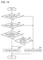
- FIG. 12 is a flowchart of a separation determination process according to the second embodiment
- FIG. 13 is a diagram showing an example of a schematic configuration of a scanning probe microscope C according to a third embodiment
- FIGS. 14A and 14B are diagrams showing a state of the cantilever 2 in a separating operation according to the third embodiment ( FIG. 14A shows a case of vibrating the cantilever 2 in the deflection direction and FIG. 14B shows a case of vibrating the cantilever 2 in a twist direction);
- FIG. 15 is a diagram showing an example of a schematic configuration of a scanning probe microscope D according to a fourth embodiment
- FIGS. 16A and 16B are diagrams illustrating a method of detecting a decrease amount of an amplitude in a non-resonant frequency in a deflection direction or a twist direction, in a cantilever according to the fourth embodiment ( FIG. 16A shows a case of vibrating the cantilever in the deflection direction and FIG. 16B shows a case of vibrating the cantilever in the twist direction);
- FIGS. 17A and 17B are diagrams illustrating a method of detecting an increase amount of an amplitude in a resonant frequency in a deflection direction or a twist direction in the cantilever according to the fourth embodiment ( FIG. 17A shows a case of vibrating the cantilever in the deflection direction and FIG. 17B shows a case of vibrating the cantilever in the twist direction);
- FIGS. 18A and 18B are diagrams illustrating a method of detecting a decrease amount of an amplitude in a resonant frequency in a deflection direction or a twist direction, in the cantilever according to the fourth embodiment ( FIG. 18A shows a case of vibrating the cantilever in the deflection direction and FIG. 18B shows a case of vibrating the cantilever in the twist direction);
- FIG. 19 is a diagram showing an example of a schematic configuration of a scanning probe microscope E according to a fifth embodiment.
- FIGS. 20A and 20B are diagrams illustrating a separation determination process according to the fifth embodiment.
- a scanning probe microscope is a scanning probe microscope using a method in which a probe is caused to contact with a sample surface thereby scanning the sample surface with the probe, that is, an intermittent measurement method.
- FIG. 1 is a diagram showing an example of a schematic configuration of a scanning probe microscope A according to a first embodiment.
- the scanning probe microscope A includes a cantilever 2 , a sample stage 4 , a movement driving unit 5 , a displacement detecting unit 6 , and a control device 7 .
- the cantilever 2 includes a probe 2 a on a tip.
- the cantilever 2 is configured such that a base end thereof is fixed and the tip is a free end.
- the cantilever 2 is an elastic lever member having a small spring constant K.
- the movement driving unit 5 moves the probe 2 a and sample S relative to each other in a three-dimensional direction.
- the movement driving unit 5 includes Z-direction driving device 51 (a driving unit) and an XY-scanner (a scanner) 52 .
- the sample stage 4 is mounted on the Z-direction driving device 51 .
- the sample S is placed on the sample stage 4 so as to be disposed to face the probe 2 a of cantilever 2 .
- the Z-direction driving device 51 moves the sample stage 4 in a direction (a Z direction) perpendicular to a horizontal surface.
- the Z-direction driving device 51 is a piezoelectric element.
- the Z-direction driving device 51 performs an approaching operation by which the sample surface approaches the probe 2 a or a separating operation by which the sample S is moved in a direction being separated from the probe 2 a by moving the sample stage 4 in the Z direction through controlling from the control device 7 .
- the XY scanner 52 moves the probe 2 a and sample S relative to each other in an XY direction through a control from the control device 7 .
- a plane parallel with a surface of the sample stage 4 is a horizontal surface, and here, is defined as an XY plane by orthogonal two axes X and Y.
- the XY scanner 52 is a piezoelectric element.
- a Z-direction driving device 51 and the XY scanner 52 may have any disposition relationship as long as a configuration thereof is capable of relative scanning for observing a three-dimensional shape.
- the displacement detecting unit 6 detects a deflection amount and a twist amount of the cantilever 2 .
- a case where the displacement detecting unit 6 detects the deflection amount and the twist amount of the cantilever 2 using an optical lever type will be described.
- the displacement detecting unit 6 includes an irradiation unit 61 and a light detection unit 62 .
- the optical irradiation unit 61 irradiates a reflection surface (not illustrated) formed on a back surface of the cantilever 2 with laser light L 1 .
- the light detection unit 62 receives the laser light L 2 reflected by the reflection surface.
- the light detection unit 62 is a photodetector including a four-divided light receiving surface 27 that receives the laser light L 2 reflected by the back surface. That is, an optical path is adjusted (in general, to be in the vicinity of the center of the light receiving surface 27 ) such that the laser light L 2 reflected by the back surface of the cantilever 2 is incident to a plurality of light receiving surfaces 27 , that is divided into four sections, of the light detection unit 62 .
- FIG. 2 is a perspective diagram showing a sample S having a slope and the cantilever 2 .
- a displacement occurs on the cantilever 2 in either or both of the Z direction and a Y direction.
- a displacement of the cantilever 2 occurring in the Z direction is referred to as a deflection amount and a displacement of the cantilever 2 occurring in the Y direction is referred to as a twist amount.
- an incidence spot position of the laser light L 2 reflected in a state where a force is not applied to the probe 2 a , in the light receiving surface 27 of the light detection unit 62 is assumed as the center position of the light receiving surface 27 .
- the state where a force is not applied to the probe 2 a is, for example, is a state of a not-deformed cantilever (hereinafter, referred to as “free state”) in which the probe 2 a and the sample surface do not contact with each other.
- free state a state of a not-deformed cantilever
- a contact mode when the probe 2 a and sample surface contact with each other, a force is applied to the probe 2 a . Therefore, the deflection amount and the twist amount is generated in the cantilever 2 . Accordingly, a reflection spot position of the laser light L 2 reflected by the back surface of the cantilever 2 where the deflection amount or the twist amount is generated is displaced from the center position. Therefore, the scanning probe microscope A becomes possible to detect a magnitude and a direction of the force applied to the probe 2 a by catching a movement direction of the spot position in the light receiving surface 27 of the light detection unit 62 .
- a change amount of the spot position from the center position depends on the twist amount or the deflection amount. Specifically, in a case where the cantilever 2 is deflected in a +Z direction, the reflection spot of the laser light L 2 in the light receiving surface 27 of the light detection unit 62 changes in a + ⁇ direction. In addition, in a case where the cantilever 2 is deflected in a ⁇ Z direction, the reflection spot of the laser light L 2 in the light receiving surface 27 of the light detection unit 62 changes in a ⁇ direction.
- the reflection spot position of the laser light L 2 in the light receiving surface 27 of the light detection unit 62 changes in a +a direction.
- the reflection spot of the laser light L 2 in the light receiving surface 27 of the light detection unit 62 changes in a ⁇ direction.
- the light detection unit 62 outputs a first detection signal according to the reflection spot position of the laser light L 2 in ⁇ Z directions of the light receiving surface 27 to the control device 7 . That is, the first detection signal is a DIF signal (the deflection signal) according to the deflection amount of the cantilever 2 .
- the light detection unit 62 outputs a second detection signal according to the reflection spot position of the laser light L 2 in ⁇ Y directions of the light receiving surface 27 to the control device 7 . That is, the second detection signal is an FFM signal (the twist signal) according to the twist amount of the cantilever 2 .
- control device 7 according to the first embodiment will be described.
- the control device 7 includes a determination unit 42 , a driving control unit 43 , and a measurement unit 44 .
- the determination unit 42 determines whether the probe 2 a has contacted with the sample surface based on the first detection signal and the second detection signal which are output from the light detection unit 62 .
- a process of determining whether the probe 2 a has contacted with the sample surface is referred to as a “contact determination process.”
- the determination unit 42 determines whether the probe 2 a is separated from the sample surface based on the first detection signal and the second detection signal which are output from the light detection unit 62 .
- a process of determining whether the probe 2 a is separated from the sample surface is referred to as a “separation determination process.”
- the driving control unit 43 controls an amount of relative movement between the probe 2 a and sample S by the movement driving unit 5 .
- the scanning probe microscope A uses an intermittent measurement method by which the sample surface is intermittently scanned by causing the probe 2 a to contact with the sample surface only in a plurality of preset measuring points. Accordingly, the driving control unit 43 controls the respective operations of the approaching operation by which the probe 2 a approaches the measuring position, the separating operation by which the probe 2 a and the sample S are separated from each other, and a moving operation by which the probe 2 a is moved to the position above the next measuring position.
- the driving control unit 43 outputs a contact operation signal for causing the probe 2 a and sample surface to contact with each other to the Z-direction driving device 51 and raises the sample S. Accordingly, the driving control unit 43 causes the probe 2 a and sample surface to contact with each other.
- the driving control unit 43 stops the approaching operation of raising the sample S by stopping the output of the contact operation signal to the Z-direction driving device 51 .
- the driving control unit 43 outputs the separating operation signal for separating the sample surface from the probe 2 a , to the Z-direction driving device 51 , and lowers the sample S. Accordingly, the driving control unit 43 causes the sample surface to be moved in a direction being separated from the probe 2 a . That is, the driving control unit 43 causes the sample surface to be retracted from a state of contacting with the probe 2 a.
- one of the features of the first embodiment is that, in the separating operation, the driving control unit 43 moves the sample S in the direction of being separated from the probe 2 a at a speed exceeding a response speed of the cantilever 2 .
- the response speed is an average movement speed that is calculated based on a resonant frequency of the cantilever 2 and amplitude with which a stable operation is possible at the resonant frequency.
- the separating operation according to the first embodiment is an operation in which the sample S is operated in the direction of being separated from the probe 2 a at the speed exceeding the response speed of the cantilever 2 .
- the driving control unit 43 stops the separating operation of lowering the sample S by stopping the output of the separating operation signal to the Z-direction driving device 51 .
- the driving control unit 43 moves the probe 2 a to a before-lowering measurement position that is located immediately above the next measurement position by outputting a driving signal to the XY scanner 52 .
- the measurement unit 44 measures an uneven shape of the sample surface in a state where the probe 2 a and the sample surface contact with each other.
- the measurement unit 44 measures the uneven shape of the sample surface by measuring a distance of relative movement of the sample surface with respect to the probe 2 a in the approaching operation (hereinafter, simply referred to as “relative distance”).
- the measurement unit 44 may calculate the relative distance based on a voltage value of the driving signal in a state where the probe 2 a and the sample surface contact with each other.
- the measurement unit 44 may directly measure the displacement of the sample stage 4 using a sensor (not illustrated) and may also directly measure a height of the sample stage 4 using a sensor (not illustrated).
- the driving control unit 43 starts the approaching operation of causing the probe 2 a to approach the sample surface by outputting the contact operation signal to the Z-direction driving device 51 and raising the sample stage 4 (Step S 101 ).
- the determination unit 42 executes the contact determination process of determining whether the probe 2 a has contacted with the sample surface, based on the first detection signal and the second detection signal which are output from the light detection unit 62 (Step S 102 ).
- the determination unit 42 stops the approaching operation (Step S 103 ). In this case, since the probe 2 a is in contact with the sample surface, a certain amount of twist or deflection occurs in the cantilever.
- the measurement unit 44 measures the uneven shape of the sample surface by measuring the relative distance (Step S 104 ).
- the driving control unit 43 starts the separating operation in which the sample S is moved in the direction of being separated from the probe 2 a at the speed exceeding the response speed of the cantilever 2 (Step S 105 ).
- the determination unit 42 executes the separation determination process of determining whether the probe 2 a is separated from the sample surface, based on the first detection signal and the second detection signal which are output from the light detection unit 62 (Step S 106 ).
- the driving control unit 43 stops the separating operation (Step S 107 ).
- the driving control unit 43 outputs the driving signal to the XY scanner 52 , thereby moving the probe 2 a to the before-lowering measurement position that is located immediately above the next measurement position (Step S 108 ).
- the driving control unit 43 lowers the cantilever 2 from the before-lowering measurement position and brings the probe 2 a into contact with the sample surface in the next measurement position, then, the measurement unit 44 starts the measurement of the relative distance again.
- the scanning probe microscope A performs operations from Steps S 101 to S 108 corresponding to respective measuring points of the sample surface to scan the sample surface intermittently.
- the determination unit 42 determines that the probe 2 a has contacted with the sample surface.
- the determination unit 42 determines that the probe 2 a has contacted with the sample surface.
- the determination unit 42 determines that the probe 2 a has contacted with the sample surface.
- a determination may be performed based on a set value corresponding to the characteristics, for example, in the determination unit 42 , it may be determined to a contact state in a case where a “square of the first detection signal” and a “square of the second detection signal” are added together and a positive number of the square root of the sum is equal to or greater than a certain value.
- the first range is a range between a deflection upper limit threshold and a deflection lower limit threshold.
- the deflection upper limit is the deflection amount of the cantilever 2 that is deflected in the +Z direction by contact between surfaces of the probe 2 a and the sample S.
- the deflection lower limit is the deflection amount of the cantilever 2 that is deflected in the ⁇ Z direction by contact between surfaces of the probe 2 a and the sample S.
- the determination unit 42 determines that the probe 2 a has contacted with the sample surface.
- the second range is a range between a twist upper limit threshold and a twist lower limit threshold.
- the twist upper limit is the twist amount of the cantilever 2 that is twisted in the +Y direction by contact between surfaces of the probe 2 a and the sample S.
- the twist lower limit is the twist amount of the cantilever 2 that is twisted in the ⁇ Y direction by contact between the probe 2 a and the sample surface. Accordingly, in a case where the twist amount, that the second detection signal output from the light detection unit 62 shows, exceeds the twist upper limit or in a case where the twist amount, that the second detection signal shows, falls below the twist lower limit, the determination unit 42 determines that the probe 2 a has contacted with the sample surface.
- the discharge passage 42 determines that the probe 2 a is separated from the sample surface.
- the predetermined amplitude is a range smaller than the displacement of the cantilever 2 in a state where the probe 2 a is in contact with the sample surface, with reference to an amplitude of the cantilever 2 due to thermal vibration in the free state.
- the separation determination process is a process of determining whether a rate of change in the amplitude in the deflection direction in the vicinity of the resonant frequency of the cantilever 2 is equal to or greater than a predetermined value, in a case where the sample S is operated in the separating direction from the probe 2 a at the speed exceeding the response speed of the cantilever 2 .
- the case where the rate of change in the amplitude in the deflection direction represents a case where the amplitude in the deflection direction rapidly increases.
- the separation determination process may be a process of determining whether the frequency of the vibration of the cantilever 2 with predetermined amplitude is the resonant frequency of the cantilever, in a case where the sample S is operated in the separating direction from the probe 2 a at the speed exceeding the response speed of the cantilever 2 .
- the determination unit 42 determines that the probe 2 a is separated from the sample surface.
- the determination unit 42 determines that the probe 2 a and the sample surface contact with each other (are not separated from each other).
- FIGS. 5A and 5B are diagrams showing a state of the cantilever 2 in a case where the sample S is moved in a direction being separated from the probe 2 a at a normal speed.
- FIGS. 6A and 6B are diagrams showing a state of the cantilever 2 in a separating operation (in a case where the sample S is operated in the direction being separated from the probe 2 a at a speed exceeding a response speed of the cantilever 2 ) according to the first embodiment.
- FIGS. 5A and 6A show side views of the cantilever 2 as viewed from the ⁇ Y direction
- FIGS. 5B and 6B show side views of the cantilever 2 as viewed from ⁇ X direction.
- the determination unit 42 determines that the probe 2 a has contacted with the sample surface. Accordingly, in contraposition with above, if the deflection amount and the twist amount of the cantilever 2 are within the predetermined ranges, the probe 2 a is not in contact with the sample surface, that is, it represents that the probe 2 a and the sample surface are separated from each other.
- the probe 2 a and the sample surface may be in contact with each other by the adsorption power.
- the adsorption power between the probe 2 a and the sample surface may be different at each measuring point. Accordingly, it is not possible to uniquely set the respective thresholds of the deflection amount and the twist amount when the probe 2 a and the sample surface are separated from each other.
- the driving control unit 43 separates the sample S from the probe 2 a at the speed exceeding the response speed of the cantilever 2 .
- the probe 2 a cannot move faster than the response speed of the cantilever 2 . Accordingly, when the sample S is separated from the probe 2 a at the speed exceeding the response speed of the cantilever 2 , even in a case where there is the adsorption power between the probe 2 a and the sample surface, the probe 2 a is immediately separated from a state of contacting with the sample surface.
- the cantilever 2 resonates with the amplitude from a state in which the probe 2 a and the sample surface contact with each other, that is, a state in which the probe 2 a is pushed upward, to the free state.
- the amplitude in the deflection direction at the resonant frequency of the cantilever 2 rapidly increases. Therefore, in a case where the vibration of the cantilever 2 with the amplitude in the deflection direction is detected at the resonant frequency (including high-order frequency) of the cantilever 2 during the separating operation, the determination unit 42 according to the first embodiment determines that the probe 2 a is separated from the sample surface. Accordingly, even in a case where there is the adsorption power between the probe 2 a and the sample surface, it is possible to certainly detect that the probe 2 a is separated from the sample surface.
- the vibration starting from the deflected state of the cantilever 2 occurs at the resonant frequency in the deflection direction.
- the determination unit 42 determines whether the deflection amount indicated by the first detection signal output from the light detection unit 62 is within the first range (Step S 201 ). In a case where the it is determined that the deflection amount, that the first detection signal output from the light detection unit 62 shows, is within the first range, the determination unit 42 determines whether the twist amount, that the second detection signal output from the light detection unit 62 shows, is within the second range (Step S 202 ). On the other hand, in a case where the deflection amount, that the first detection signal output from the light detection unit 62 shows, is out of the first range, the determination unit 42 determines that the probe 2 a is not separated from the sample surface (Step S 206 ).
- the determination unit 42 determines whether the frequency of the first detection signal is the resonant frequency of the cantilever 2 (Step S 203 ). On the other hand, in a case where it is determined that the twist amount, that the second detection signal output from the light detection unit 62 shows, is out of the second range, the determination unit 42 determines that the probe 2 a is not separated from the sample surface (Step S 206 ).
- the determination unit 42 determines whether the rate of change in the deflection amount, that the first signal shows, exceeds a predetermined value (Step S 204 ). Meanwhile, in a case where it is determined that the frequency of the first detection signal is not the resonant frequency of the cantilever 2 , the determination unit 42 determines that the probe 2 a is not separated from the sample surface (Step S 206 ).
- the determination unit 42 determines that the probe 2 a is separated from the sample surface (Step S 205 ). Meanwhile, in a case where the change in deflection amount, that the first detection signal shows, exceeds a predetermined value, the determination unit 42 determines that the probe 2 a is not separated from the sample surface (Step S 206 ).
- the process of Step S 202 is executed after the process of Step S 201 ; however, it is not limited thereto.
- the determination unit 42 of the present embodiment may perform the process of Step S 201 after the process of Step S 202 and may execute the process of Step S 201 and the process of S 202 in parallel.
- the determination unit 42 may execute the process of Step S 204 after the process of Step S 203 , and may execute the process of Step S 203 and the process of S 204 in parallel.
- the scanning probe microscope A determines that the probe 2 a is separated from the sample surface.
- the scanning probe microscope A stops the separating operation by the Z-direction driving device 51 at a moment of time when it is determined that the probe 2 a is separated from the sample surface and relatively moves the probe 2 a and the sample to a position where the probe 2 a is located immediately above the next measuring point of the sample S.
- the scanning probe microscope A is operated at an optimal separation distance at the respective measuring points of the sample S, it is possible to achieve the measurement of the uneven shape in the sample surface in the shortest time. Therefore, the scanning probe microscope A is possible to improve the efficiency of measuring the uneven shape in the sample surface.
- the first detection signal showing the deflection amount may drift due to a temperature change or the like in some cases.
- the scanning probe microscope A according to the first embodiment successively determines whether the probe 2 a is separated from the sample surface. According to this, the scanning probe microscope A is not affected by the drift and can be operated at the optimal separation distance.
- the Z-direction driving device 51 is necessary to perform the separating operation in which the sample S is moved in the direction being separated from the probe 2 a at a speed at which the vibration does not occur.
- the Z-direction driving device 51 may have a configuration using a laminated piezoelectric element 510 .
- the Z-direction driving device 51 includes the laminated piezoelectric element 510 , flat springs 511 and 512 that have the same spring constant, support-plates 521 and 522 that respectively fix the flat springs 511 and 512 , and a base 530 .
- the sample stage 4 and the sample S are provided via the flat spring 511 .
- the base 530 is provided via the flat spring 512 .
- the weight of the base 530 corresponds to the weight of the sample stage 4 and sample S.
- the Z-direction driving device 51 In a case where the Z-direction driving device 51 is fixed, the Z-direction driving device 51 is fixed at the center of each of the support plates 521 and 522 . Accordingly, the Z-direction driving device 51 can prevent the vibration from being transmitted to the surroundings even when performing the separating operation.
- the scanning probe microscope B according to the second embodiment performs a separation determination process based on the speed change of the cantilever 2 in the deflection direction, unlike the “separation determination process” according to the first embodiment.
- the scanning probe microscope B according to the second embodiment performs the same process as the “contact determination process” according to the first embodiment.
- FIG. 9 is a diagram showing an example of a schematic configuration of the scanning probe microscope B according to the second embodiment.
- the scanning probe microscope B includes a cantilever 2 , a sample stage 4 , a movement driving unit 5 , a displacement detecting unit 6 , and a control device 7 B.
- the control device 7 B includes a determination unit 42 B, a driving control unit 43 B, and a measurement unit 44 .
- the determination unit 42 B performs the contact determination process of determining whether the probe 2 a has contacted with the sample surface, based on the first detection signal and the second detection signal which are output from the light detection unit 62 .
- the contact determination process of the determination unit 42 B is the same as the contact determination process according to the first embodiment.
- the determination unit 42 B performs the separation determination process of determining whether the probe 2 a is separated from the sample surface, based on the first detection signal and the second detection signal which are output from the light detection unit 62 .
- the separation determination process of the determination unit 42 B is to determine the separation of the probe 2 a with respect to the sample surface, based on the speed change of the cantilever 2 in the deflection direction during the separating operation.
- the driving control unit 43 B causes the sample S to be moved in the direction of being separated from the probe 2 a at a speed equal to or lower than the response speed of the cantilever 2 . That is, regarding the separating operation, in the first embodiment, the sample S is operated in the direction of being separated from the probe 2 a at the speed exceeding the response speed of the cantilever 2 , whereas in the second embodiment, the sample S is moved in the direction of being separated from the probe 2 a at the speed equal to or lower than the response speed of the cantilever 2 .
- the operations relating to the driving control unit 43 B other than the separating operation are the same as those of the driving control unit 43 .
- the determination unit 42 B determines the separation of the probe 2 a with respect to the sample surface, based on the speed change of the cantilever 2 in the deflection direction during the separating operation in which the sample S is separated from the probe 2 a at the speed equal to or lower than the response speed of the cantilever 2 .
- the determination unit 42 B can calculate the speed change of the cantilever 2 in the deflection direction from a ratio (Vd/H) between a deflection amount Vd of the cantilever 2 and a separated distance H of the sample S from the probe 2 a .
- the determination unit 42 B can calculate the speed change of the cantilever 2 in the deflection direction by differentiating the deflection amount Vd of the cantilever 2 .
- the determination unit 42 B determines that the probe 2 a is separated from the sample surface.
- the determination unit 42 B determines that the probe 2 a is separated from the sample surface.
- FIGS. 10A and 10B are graphs showing the speed change of the cantilever 2 in the deflection direction, in the separating operation according to the second embodiment.
- FIG. 10A is a graph of the speed change of the cantilever 2 in the deflection direction in a case where there is no adsorption power between the probe 2 a and the sample S.
- FIG. 10B is a graph of the speed change of the cantilever 2 in the deflection direction in a case where there is the adsorption power between the probe 2 a and the sample S.
- FIGS. 10A is a graph of the speed change of the cantilever 2 in the deflection direction in a case where there is no adsorption power between the probe 2 a and the sample S.
- FIGS. 10A is a graph of the speed change of the cantilever 2 in the deflection direction in a case where there is no adsorption power between the probe 2 a and the sample S.
- FIGS. 10A is a graph of the
- FIG. 11A and 11B are diagrams showing a state of the cantilever 2 in the separating operation (in a case where the sample S is operated in the direction being separated from the probe 2 a at a speed equal to or lower than the response speed of the cantilever 2 ) according to the second embodiment.
- FIG. 11A shows a side view of the cantilever 2 as viewed from the ⁇ Y direction
- FIG. 11B shows a side view of the cantilever 2 as viewed from ⁇ X direction.
- the determination unit 42 B determines that the probe 2 a is separated from the sample surface.
- the determination unit 42 B can certainly detect the separation between the probe 2 a and the sample S.
- the predetermined value is a value lower than the speed of the cantilever 2 in the deflection direction.
- the determination unit 42 B determines that the probe 2 a is separated from the sample surface. Accordingly, even in a case where there is the adsorption power between the probe 2 a and the sample S, the determination unit 42 B can certainly detect the separation between the probe 2 a and the sample S.
- the determination unit 42 B determines whether the deflection amount indicated by the first detection signal output from the light detection unit 62 is within the first range (Step 301 ). In a case where the it is determined that the deflection amount, that the first detection signal output from the light detection unit 62 shows, is within the first range, the determination unit 42 B determines whether the twist amount, that the second detection signal output from the light detection unit 62 shows, is within the second range (Step S 302 ). On the other hand, in a case where the deflection amount, that the first detection signal output from the light detection unit 62 shows, is out of the first range, the determination unit 42 B determines that the probe 2 a is not separated from the sample surface (Step S 306 ).
- the determination unit 42 B determines whether the speed of the cantilever 2 calculated based on the first detection signal is equal to or lower than a predetermined value (Step S 303 ). On the other hand, in a case where it is determined that the twist amount, that the second detection signal output from the light detection unit 62 shows, is out of the second range, the determination unit 42 B determines that the probe 2 a is not separated from the sample surface (Step S 306 ).
- the determination unit 42 B determines that the probe 2 a is separated from the sample surface (Step S 305 ). Meanwhile, in a case where it is determined that the speed of the cantilever 2 exceeds a predetermined value, the determination unit 42 B determines whether the speed direction of the cantilever 2 is reversed (Step S 304 ).
- the determination unit 42 B determines that the probe 2 a is separated from the sample surface (Step S 305 ). Meanwhile, in a case where it is determined that the speed direction of the cantilever 2 is not reversed, the determination unit 42 B determines that the probe 2 a is not separated from the sample surface (Step S 306 ).
- the process of Step S 302 is executed after the process of Step S 301 ; however, it is not limited thereto.
- the determination unit 42 B of the present embodiment may perform the process of Step S 301 after the process of Step S 302 and may execute the process of Step S 301 and the process of S 302 in parallel.
- the determination unit 42 B may execute the process of Step S 304 after the process of Step S 303 , and may execute the process of Step S 303 and the process of S 304 in parallel.
- the scanning probe microscope B determines the separation of the probe 2 a with respect to the sample surface, based on the speed change of the cantilever 2 in the deflection direction during the separating operation in which the sample S is separated from the probe 2 a at the speed not exceeding the response speed of the cantilever 2 .
- the determination unit 42 B determines that the probe 2 a is separated from the sample surface. In addition, in a case where the probe 2 a is reversed in the speed direction, the determination unit 42 B determines that the probe 2 a is separated from the sample surface.
- the scanning probe microscope B is operated at the optimal separation distance at the respective measuring points of the sample S even in a case where there is the adsorption power between the probe 2 a and sample S, it is possible to achieve the measurement of the uneven shape in the sample surface in the shortest time. Therefore, the scanning probe microscope B is possible to improve the efficiency of measuring the uneven shape in the sample surface.
- the sample and the probe 2 a are separated from each other by lowering the sample S; however, it is not limited thereto.
- the driving control unit 43 B may separate the sample S and the probe 2 a from each other by raising the probe 2 a.
- the scanning probe microscope C according to the third embodiment performs a separation determination process based on an increase of the amplitude of the vibration in the cantilever 2 or a change of the vibration frequency of the vibration, unlike the “separation determination process” according to the first embodiment.
- the scanning probe microscope C according to the third embodiment performs the same process as the “contact determination process” according to the first embodiment.
- FIG. 13 is a diagram showing an example of a schematic configuration of the scanning probe microscope C according to the third embodiment.
- the scanning probe microscope C includes a cantilever 2 , a sample stage 4 , a movement driving unit 5 , a displacement detecting unit 6 , and a control device 7 C.
- the control device 7 C includes a determination unit 42 C, the driving control unit 43 B, and a measurement unit 44 .
- the determination unit 42 C performs the contact determination process of determining whether the probe 2 a has contacted with the sample surface, based on the first detection signal and the second detection signal which are output from the light detection unit 62 .
- the contact determination process of the determination unit 42 C is the same as the contact determination process according to the first embodiment.
- the determination unit 42 C performs the separation determination process of determining whether the probe 2 a is separated from the sample surface, based on the first detection signal and the second detection signal which are output from the light detection unit 62 .
- the base end is fixed and the tip (the probe 2 a ) is configured as a free end. Therefore, in a case where the probe 2 a is not in contact with the sample surface, that is, is in a separated state, the cantilever 2 resonates with large amplitude due to a thermal vibration.
- a state of the cantilever 2 of which the base end is a fixed end and the tip (probe 2 a ) is the free end is referred to as a cantilever state.
- the probe 2 a in a case where the probe 2 a is in contact with the sample surface, the probe 2 a becomes to be fixed by the sample surface. That is, both the base end and the tip of the cantilever 2 become the fixed end. Therefore, the amplitude of the resonance due to the thermal vibration becomes smaller amplitude as compared to the cantilever state.
- the state of the cantilever 2 of which both the base end and the tip are the fixed end is referred to as a doubly-supported state.
- the determination unit 42 C determines the separation of the probe 2 a with respect to the sample surface, based on the increase of the amplitude in the vibration of the cantilever 2 . For example, in a case where the amplitude of the vibration in the cantilever 2 reaches a value equal to or larger than a predetermined value during the separating operation, the determination unit 42 C determines that the probe 2 a and the sample surface have been separated from each other.
- the amplitude of the vibration in the cantilever 2 is at least one of deflection amplitude and twist amplitude.
- the predetermined value is set based on the amplitude of the vibration of the cantilever 2 in the doubly-supported state.
- the resonant frequency of the cantilever 2 resonating due to the thermal vibration is different in the cantilever state and the doubly-supported state. Therefore, the state where the probe 2 a is in contact with the sample surface is shifted to the state where the probe 2 a is separated from the sample surface, the resonant frequency of the cantilever 2 changes.
- the resonant frequency of the cantilever 2 in the cantilever state is referred to as a cantilever resonant frequency.
- the resonant frequency of the cantilever 2 in the doubly-supported state is referred to as a doubly-supported-beam resonant frequency.
- the determination unit 42 C determines the separation of the probe 2 a with respect to the sample surface, based on the change in the resonant frequency of the vibration in the cantilever 2 during the separating operation. For example, in a case where the change in the vibration frequency of the cantilever 2 during the separating operation reaches a value equal to or greater than a predetermined value, the determination unit 42 C determines that the probe 2 a and the sample surface have been separated from each other.
- the vibration in the cantilever 2 is a frequency of the vibration in at least one direction of the deflection direction and the twist direction.
- the predetermined value is set based on the doubly-supported-beam resonant frequency.
- the scanning probe microscope C determines the separation of the probe 2 a with respect to the sample surface, based on the increase of the vibration in the cantilever 2 or the change of the vibration frequency of the vibration during the separating operation. Accordingly, since the scanning probe microscope C is operated at the optimal separation distance at the respective measuring points of the sample S even in a case where there is the adsorption power between the probe 2 a and sample S, it is possible to achieve the measurement of the uneven shape in the sample surface in the shortest time. Therefore, the scanning probe microscope C is possible to improve the efficiency of measuring the uneven shape in the sample surface.
- the scanning probe microscope D according to the fourth embodiment includes an oscillation unit 3 and performs a separation determination process based on a change in amplitude of a predetermined frequency in a deflection direction or a twist direction of the cantilever 2 , unlike the “separation determination process” according to the first embodiment.
- the scanning probe microscope D according to the fourth embodiment performs the same process as the “contact determination process” according to the first embodiment.
- FIG. 15 is a diagram showing an example of a schematic configuration of the scanning probe microscope D according to the fourth embodiment.
- the scanning probe microscope D includes a cantilever 2 , an oscillation unit 3 , a sample stage 4 , a movement driving unit 5 , a displacement detecting unit 6 , and a control device 7 D.
- the oscillation unit 3 relatively vibrates the sample S and the cantilever 2 at a predetermined frequency in a separating operation.
- the oscillation unit 3 may excite the cantilever 2 , or may excite the sample stage 4 .
- a direction of the relative vibration between the sample S and the cantilever 2 at a predetermined frequency may be a direction (Z-direction) perpendicular to the horizontal plane or a horizontal direction (Y-direction) of the sample stage 4 .
- the predetermined frequency is referred to as an oscillation frequency.
- the control device 7 D includes a determination unit 42 D, a driving control unit 43 D, and a measurement unit 44 .
- the determination unit 42 D performs a separation determination process of determining whether a probe 2 a is separated from a sample surface, based on a first detection signal and a second detection signal which are output from a light detection unit 62 .
- the separation determination process of the determination unit 42 D is to determine the separation of the probe 2 a with respect to the sample surface, based on the change in amplitude of the oscillation frequency in the deflection direction or the twist direction of the cantilever 2 .
- the driving control unit 43 D has the same function as that of the driving control unit 43 B. Further, the driving control unit 43 D controls the operation of the oscillation unit 3 . That is, the driving control unit 43 D controls relative vibration between the sample S and the cantilever 2 .
- FIGS. 16A, 16B, 17A, 17B, 18A, and 18B the separation determination process according to the fourth embodiment will be described with reference FIGS. 16A, 16B, 17A, 17B, 18A, and 18B .
- a method of detecting a decrease amount of an amplitude in a non-resonant frequency in the deflection direction or the twist direction of the cantilever there are roughly three methods of “a method of detecting a decrease amount of an amplitude in a non-resonant frequency in the deflection direction or the twist direction of the cantilever”, “a method of detecting an increase amount of an amplitude in a resonant frequency in the deflection direction or the twist direction of the cantilever”, and ““a method of detecting a decrease amount of an amplitude in the resonant frequency in the deflection direction or the twist direction of the cantilever.”
- FIGS. 16A and 16B >
- the oscillation frequency is set to a non-resonant frequency of the cantilever 2 .
- the oscillation unit 3 slightly vibrates the sample S relative to the cantilever 2 at a non-resonant frequency in the separating operation.
- the angle of the cantilever 2 changes with the probe 2 a as a fulcrum. That is, the angle change of the cantilever 2 is detected as large amplitude of the cantilever 2 in a detection method using an optical lever type.
- the angle change of the cantilever 2 decreases.
- the amplitude of the cantilever 2 is at least one of the amplitude in the deflection direction and the amplitude in the twist direction.
- the amplitude in the deflection direction is a deflection amount indicated by the first detection signal.
- the amplitude in the twist direction is a twist amount indicated by the second detection signal.
- the determination unit 42 D determines that the probe 2 a is separated from the surface of the sample when the decrease amount of the amplitude at the non-resonant frequency in the deflection direction or the twist direction of the cantilever 2 exceeds a predetermined value in the separating operation.
- the predetermined value is set based on the deflection amount or the twist amount detected in a state where the probe 2 a is in contact with the surface of the sample in the separating operation.
- it may slightly vibrate the cantilever 2 at the non-resonant frequency in the deflection direction, or may vibrate the cantilever 2 in the horizontal direction.
- it may slightly vibrate the sample S at the non-resonant frequency in the deflection direction, or may vibrate the sample S in the horizontal direction.
- FIGS. 17A and 17B >
- the oscillation frequency is set to a cantilever resonant frequency.
- the oscillation unit 3 slightly vibrates the sample S relative to the cantilever 2 at a cantilever resonant frequency in the separating operation.
- the cantilever 2 is in a doubly-supported state when the probe 2 a is in contact with the surface of the sample. For this reason, even if being excited at the cantilever resonant frequency by the oscillation unit 3 , the cantilever 2 does not resonate and vibrates with small amplitude.
- the cantilever 2 when the probe 2 a and the surface of the sample are separated from each other in the separating operation, since the probe 2 a is away from the surface of the sample, the cantilever 2 is in a cantilever state. Therefore, the cantilever 2 resonates by being excited with the cantilever resonant frequency by the oscillation unit 3 , and vibrates with large amplitude.
- the determination unit 42 D determines the separation of the probe 2 a from the surface of the sample based on the increase in amplitude of the vibration of the cantilever 2 at the cantilever resonant frequency in the separation operation. For example, the determination unit 42 D determines that the probe 2 a is separated from the surface of the sample when the increase amount of the vibration amplitude of the cantilever 2 at the cantilever resonant frequency exceeds a predetermined value in the separating operation.
- the vibration amplitude of the cantilever 2 is at least one of the deflection amplitude and the twist amplitude.
- it may slightly vibrate the cantilever 2 at the cantilever resonant frequency in the deflection direction, or may vibrate the cantilever 2 at the cantilever resonant frequency in the horizontal direction.
- it may slightly vibrate the sample S at the cantilever resonant frequency in the deflection direction, or may vibrate the sample S at the cantilever resonant frequency in the horizontal direction.
- the oscillation frequency is the cantilever resonant frequency of the cantilever 2 in the deflection direction.
- the oscillation frequency is the cantilever resonant frequency of the cantilever 2 in the horizontal direction.
- FIGS. 18A and 18B >
- the oscillation frequency is set to a doubly-supported-beam resonant frequency.
- the oscillation unit 3 slightly vibrates the sample S relative to the cantilever 2 at the doubly-supported-beam resonant frequency in the separating operation.
- the cantilever 2 is in a doubly-supported state when the probe 2 a is in contact with the surface of the sample. For this reason, the cantilever 2 resonates by being excited at the doubly-supported-beam resonant frequency by the oscillation unit 3 , and vibrates with large amplitude.
- the cantilever 2 when the probe 2 a and the surface of the sample are separated from each other in the separating operation, since the probe 2 a is away from the surface of the sample, the cantilever 2 is in a cantilever state. For this reason, even if being excited at the doubly-supported-beam resonant frequency by the oscillation unit 3 , the cantilever 2 does not resonate and vibrates with small amplitude.
- the determination unit 42 D determines the separation of the probe 2 a from the surface of the sample based on the decrease in amplitude of the vibration of the cantilever 2 at doubly-supported-beam resonant frequency in the separation operation.
- the determination unit 42 D determines that the probe 2 a is separated from the surface of the sample when the decrease amount of the vibration amplitude of the cantilever 2 at the doubly-supported-beam resonant frequency exceeds a predetermined value in the separating operation.
- the vibration amplitude of the cantilever 2 is at least one of the deflection amplitude and the twist amplitude.
- it may slightly vibrate the cantilever 2 at the doubly-supported-beam resonant frequency in the deflection direction, or may vibrate the cantilever 2 at the doubly-supported-beam resonant frequency in the horizontal direction.
- it may slightly vibrate the sample S at the doubly-supported-beam resonant frequency in the deflection direction, or may vibrate the sample S at the doubly-supported-beam resonant frequency in the horizontal direction.
- the oscillation frequency is the doubly-supported-beam resonant frequency of the cantilever 2 in the deflection direction.
- the oscillation frequency is the doubly-supported-beam resonant frequency of the cantilever 2 in the horizontal direction.
- the separation of the probe 2 a from the surface of the sample is determined under conditions that the deflection amount indicated by the first detection signal output from the light detection unit 62 is within a first range and the twist direction indicated by the second detection signal output from the light detection unit 62 is within a second range.
- the scanning probe microscope D includes the oscillation unit 3 that relatively vibrates the sample S and the cantilever 2 at a predetermined frequency in the separating operation and the determination unit 42 D that determines the separation of the probe 2 a from the surface of the sample based on the change in amplitude at the predetermined frequency in the deflection direction or the twist direction of the cantilever 2 during the separating operation. Accordingly, since the scanning probe microscope D is operated at the optimal separation distance at the respective measuring points of the sample S even in a case where there is the adsorption power between the probe 2 a and sample S, it is possible to achieve the measurement of the uneven shape in the sample surface in the shortest time. Therefore, the scanning probe microscope D is possible to improve the measurement efficiency of the uneven shape in the sample surface.
- the method of slightly vibrating at the non-resonate frequency in the deflection or twist direction is suitable for the case where the amplitude sharply decreases at the moment the probe 2 a separates from the surface of the sample, the response is fast, and the operation is performed at a high speed.
- the method of adding minute amplitude to the resonant frequency makes it possible to detect with the amplitude smaller than the non-resonant frequency, so it has little influence on the measurement of the uneven shape.
- the scanning probe microscope E according to a fifth embodiment includes an oscillation unit 3 as in the fourth embodiment and performs a separation determination process based on a phase difference between a phase of vibration in a deflection direction or a twist direction of the cantilever 2 and a phase of a resonant frequency excited by the oscillation unit 3 , unlike the “separation determination process” according to the first embodiment.
- the scanning probe microscope E according to the fifth embodiment performs the same process as the “contact determination process” according to the first embodiment.
- FIG. 19 is a diagram showing an example of a schematic configuration of the scanning probe microscope E according to the fifth embodiment.
- the scanning probe microscope E includes a cantilever 2 , an oscillation unit 3 , a sample stage 4 , a movement driving unit 5 , a displacement detecting unit 6 , and a control device 7 E.
- the control device 7 E includes a determination unit 42 E, a driving control unit 43 D, and a measurement unit 44 .
- the determination unit 42 E performs a separation determination process of determining whether a probe 2 a is separated from a sample surface, based on a first detection signal and a second detection signal which are output from a light detection unit 62 .
- the separation determination process of the determination unit 42 E is to determine the separation of the probe 2 a with respect to the sample surface, based on the phase difference between the phase of vibration in the deflection direction or the twist direction of the cantilever 2 and the phase of the resonant frequency excited by the oscillation unit 3 .
- the oscillation frequency is set to a cantilever resonant frequency.
- the oscillation unit 3 causes the sample S and the cantilever 2 to slightly vibrate relatively to each other at a cantilever resonant frequency in the separating operation.
- the cantilever 2 is both-end supported in the state where the probe 2 a is in contact with the surface of the sample. For this reason, even if being excited at the cantilever resonant frequency by the oscillation unit 3 , the cantilever 2 does not resonate and vibrates with non-resonance. Therefore, the phase difference between the phase of vibration in the cantilever 2 and the phase of the oscillation frequency excited by the oscillation unit 3 is small.
- the cantilever 2 when the probe 2 a and the surface of the sample are separated from each other in the separating operation, since the probe 2 a is away from the surface of the sample, the cantilever 2 is in a cantilever state. Therefore, the cantilever 2 resonates by being excited with the cantilever resonant frequency by the oscillation unit 3 . Accordingly, the phase difference between the phase of vibration in the cantilever 2 and the phase of the oscillation frequency excited by the oscillation unit 3 is approximately 90 degrees. That is, the phase of vibration in the cantilever 2 has a phase delayed by 90 degrees from the phase of the oscillation frequency excited by the oscillation unit 3 .
- the determination unit 42 E determines the separation of the probe 2 a from the surface of the sample based on the phase difference between the phase of vibration in the deflection direction or the twist direction of the cantilever 2 and the phase of the resonant frequency excited by the oscillation unit 3 in the separation operation.
- the determination unit 42 E determines that the probe 2 a is separated from the surface of the sample when the phase difference between the phase of vibration in the deflection direction or the twist direction of the cantilever 2 and the phase of the resonant frequency excited by the oscillation unit 3 exceeds a predetermined value in the separating operation.
- it may slightly vibrate the cantilever 2 at the cantilever resonant frequency in the deflection direction, or may vibrate the cantilever 2 at the cantilever resonant frequency in the horizontal direction.
- it may slightly vibrate the sample S at the cantilever resonant frequency in the deflection direction, or may vibrate the sample S at the cantilever resonant frequency in the horizontal direction.
- the oscillation frequency is the cantilever resonant frequency of the cantilever 2 in the deflection direction.
- the oscillation frequency is the cantilever resonant frequency of the cantilever 2 in the horizontal direction.
- the separation of the probe 2 a from the surface of the sample is determined under conditions that the deflection amount indicated by the first detection signal output from the light detection unit 62 is within a first range and the twist direction indicated by the second detection signal output from the light detection unit 62 is within a second range.
- the scanning probe microscope E includes the oscillation unit 3 that relatively vibrates the sample S and the cantilever 2 at a predetermined frequency in the separating operation and the determination unit 42 E that determines the separation of the probe 2 a from the surface of the sample based on the phase difference between the phase of vibration in the deflection direction or the twist direction of the cantilever 2 and the phase of the resonant frequency excited by the oscillation unit 3 during the separating operation. Accordingly, since the scanning probe microscope E is operated at the optimal separation distance at the respective measuring points of the sample S even in a case where there is the adsorption power between the probe 2 a and sample S, it is possible to achieve the measurement of the uneven shape in the sample surface in the shortest time. Therefore, the scanning probe microscope E is possible to improve the measurement efficiency of the uneven shape in the sample surface.
- the scanning probe microscope does not determine whether the probe 2 a is separated from the surface of the sample by separating it from the surface of the sample by a preset “separation distance” as in the related art, but determines whether the probe 2 a and the surface of the sample are separated from each other while performing the separating operation.
- the separating operation is stopped. Then, the scanning probe microscope allows the probe to move to the position above the next measuring point after stopping the separating operation.
- a method may be considered in which it is determined that the probe 2 a is not in contact with the surface of the sample, that is, the probe 2 a and the surface of the sample are separated from each other.
- the probe 2 a and the surface of the sample may be in contact with each other due to the adsorption power, and thus it is not possible to correctly detect that the probe and the surface of the sample are separated from each other.
- the scanning probe microscope of one embodiment of the present disclosure it is possible to reliably detect the separation of the probe 2 a from the surface of the sample by applying the separation determination process according to any one of the first to fifth embodiments during the separating operation.
- the approaching operation is performed, and (2) it is determined whether the probe 2 a and the surface of the sample are in contact with each other.
- the scanning probe microscope when it is determining that the probe 2 a and the surface of the sample are in contact with each other, (3) the approaching operation is stopped and the relative distance is measured. Then, according to the scanning probe microscope, after the relative distance is measured, and (4) the separating operation is started and whether the probe 2 a and the surface of the sample are separated from each other is determined in the separation determination process according to any one of the first to fifth embodiments during the separating operation.
- the scanning probe microscope determines in the separation determination process according to any one of the first to fifth embodiments whether the probe 2 a and the surface of the sample are separated from each other while moving the probe 2 a to the position above the next measuring point.
- the scanning probe microscope continues the movement when it is determined that the probe 2 a and the surface of the sample are separated from each other, and when the probe 2 a and the surface of the sample are not in contact with each other, returns to (5) described above to execute the separating operation and start the separation determination process according to any one of the first to fifth embodiments.
- the scanning probe microscope can avoid the probe 2 a from colliding with the sample in the movement to the position above the next measuring point.
- the sample S is moved in the direction being separated from the probe 2 a .
- the probe 2 a may be moved in a direction being separated from the sample S in the separating operation.
- the control devices 7 , and 7 B to 7 E in the above-described embodiments may be implemented by a computer. In this case, it may be realized by recording a program for achieving the functions thereof on a computer-readable recording medium and causing a computer system to read and execute the program recorded on the recording medium.
- the “computer system” used here is assumed to include an OS and hardware such as peripheral devices.
- the “computer-readable recording medium” refers to a portable medium such as a flexible disk, a magneto-optical disc, a ROM, or a CD-ROM, and a storage apparatus such as a hard disk embedded in the computer system.
- the “computer-readable recording medium” is assumed to include a computer-readable recording medium for dynamically holding a program for a short time as in a communication line when the program is transmitted via a network such as the Internet or a communication circuit such as a telephone circuit and a computer-readable recording medium for holding the program for a predetermined time as in a volatile memory inside the computer system serving as a server or a client.
- the above program may realize part of the above-described functions, it may implement the above-described functions in combination with a program already recorded on the computer system, or the above-described functions may be implemented using a programmable logic device such as a field programmable gate array (FPGA).
- FPGA field programmable gate array
Landscapes
- Physics & Mathematics (AREA)
- General Physics & Mathematics (AREA)
- Health & Medical Sciences (AREA)
- General Health & Medical Sciences (AREA)
- Nuclear Medicine, Radiotherapy & Molecular Imaging (AREA)
- Radiology & Medical Imaging (AREA)
- Engineering & Computer Science (AREA)
- Power Engineering (AREA)
- Length Measuring Devices With Unspecified Measuring Means (AREA)
- A Measuring Device Byusing Mechanical Method (AREA)
Abstract
Description
Claims (15)
Applications Claiming Priority (2)
| Application Number | Priority Date | Filing Date | Title |
|---|---|---|---|
| JP2017063530A JP6885585B2 (en) | 2017-03-28 | 2017-03-28 | Scanning probe microscope and its scanning method |
| JP2017-063530 | 2017-03-28 |
Publications (2)
| Publication Number | Publication Date |
|---|---|
| US20180284151A1 US20180284151A1 (en) | 2018-10-04 |
| US10345335B2 true US10345335B2 (en) | 2019-07-09 |
Family
ID=61832298
Family Applications (1)
| Application Number | Title | Priority Date | Filing Date |
|---|---|---|---|
| US15/937,306 Active US10345335B2 (en) | 2017-03-28 | 2018-03-27 | Scanning probe microscope and scanning method thereof |
Country Status (4)
| Country | Link |
|---|---|
| US (1) | US10345335B2 (en) |
| EP (1) | EP3382404A3 (en) |
| JP (1) | JP6885585B2 (en) |
| CN (4) | CN115752351A (en) |
Families Citing this family (6)
| Publication number | Priority date | Publication date | Assignee | Title |
|---|---|---|---|---|
| JP7261560B2 (en) * | 2018-10-31 | 2023-04-20 | 株式会社ミツトヨ | Surface texture measuring method and surface texture measuring device |
| WO2021020111A1 (en) * | 2019-07-30 | 2021-02-04 | 国立大学法人京都大学 | Measuring device, atomic force microscope, and measurement method |
| JP7318471B2 (en) * | 2019-10-08 | 2023-08-01 | 株式会社島津製作所 | Scanning probe microscope and method for adjusting position of scanning probe microscope |
| CN110553604A (en) * | 2019-10-16 | 2019-12-10 | 合肥学院 | water turbine blade blank profile measuring and machining allowance analyzing method |
| JP7351778B2 (en) * | 2020-03-18 | 2023-09-27 | 株式会社日立ハイテクサイエンス | Scanning probe microscope and setting method |
| WO2022065928A1 (en) | 2020-09-24 | 2022-03-31 | 파크시스템스 주식회사 | Method for measuring, by measurement device, characteristics of surface of object to be measured, atomic force microscope for performing same method, and computer program stored in storage medium to perform same method |
Citations (12)
| Publication number | Priority date | Publication date | Assignee | Title |
|---|---|---|---|---|
| JPH1062158A (en) | 1996-08-26 | 1998-03-06 | Seiko Instr Inc | Atomic force microscope-type surface roughness gage |
| JP2001033373A (en) | 1999-07-27 | 2001-02-09 | Hitachi Constr Mach Co Ltd | Scanning probe microscope |
| US20060219901A1 (en) | 2005-03-08 | 2006-10-05 | Masatoshi Yasutake | Working method using scanning probe |
| JP2007085764A (en) | 2005-09-20 | 2007-04-05 | Hitachi Kenki Fine Tech Co Ltd | Probe control method of scanning probe microscope |
| US20070266780A1 (en) | 2006-04-20 | 2007-11-22 | Shuichi Baba | Scanning Probe Microscope |
| US20070277599A1 (en) | 2006-05-31 | 2007-12-06 | Wang Chikuang C | Atomic force microscope technique for minimal tip damage |
| US20070295064A1 (en) * | 2005-10-07 | 2007-12-27 | Degertekin Fahrettin L | Methods of imaging in probe microscopy |
| US20080087820A1 (en) * | 2006-05-10 | 2008-04-17 | Toru Kurenuma | Probe control method for scanning probe microscope |
| US20120319679A1 (en) * | 2011-06-16 | 2012-12-20 | Hitachi, Ltd. | Magnetic force microscope and magnetic field observation method using same |
| US20130205454A1 (en) | 2007-12-19 | 2013-08-08 | Hitachi, Ltd. | Scanning probe microscope |
| US20140092716A1 (en) * | 2012-09-28 | 2014-04-03 | Hitachi High-Technologies Corporation | Method and apparatus for inspecting thermal assist type magnetic head |
| US20150338437A1 (en) * | 2014-08-05 | 2015-11-26 | National Institute Of Standards And Technology | Intermittent contact resonance atomic force microscope and process for intermittent contact resonance atomic force microscopy |
Family Cites Families (36)
| Publication number | Priority date | Publication date | Assignee | Title |
|---|---|---|---|---|
| JPS5829153A (en) * | 1981-08-12 | 1983-02-21 | Mitsubishi Electric Corp | Wobbler for optical pickup |
| DE69309318T2 (en) * | 1992-01-10 | 1997-10-30 | Hitachi, Ltd., Tokio/Tokyo | Method and device for observing a surface |
| US5412980A (en) * | 1992-08-07 | 1995-05-09 | Digital Instruments, Inc. | Tapping atomic force microscope |
| JP3131517B2 (en) * | 1992-12-25 | 2001-02-05 | オリンパス光学工業株式会社 | Scanning probe microscope equipment |
| JPH09264897A (en) * | 1996-03-28 | 1997-10-07 | Hitachi Constr Mach Co Ltd | Scanning probe microscope |
| JPH10282125A (en) * | 1997-04-04 | 1998-10-23 | Nikon Corp | Cantilever, scanning probe microscope and sample observation method using the same |
| JP3274087B2 (en) * | 1997-07-11 | 2002-04-15 | セイコーインスツルメンツ株式会社 | Scanning probe microscope |
| JP2002350320A (en) * | 2001-05-25 | 2002-12-04 | Olympus Optical Co Ltd | Scanning probe microscope |
| JP2003202284A (en) * | 2002-01-09 | 2003-07-18 | Hitachi Ltd | Scanning probe microscope, sample observation method and device manufacturing method using the same |
| JP3908041B2 (en) * | 2002-01-25 | 2007-04-25 | 日本電子株式会社 | Method for measuring oscillation amplitude of cantilever in non-contact scanning probe microscope and scanning probe microscope |
| US7473887B2 (en) * | 2002-07-04 | 2009-01-06 | University Of Bristol Of Senate House | Resonant scanning probe microscope |
| JP3925380B2 (en) * | 2002-10-01 | 2007-06-06 | 株式会社日立製作所 | Scanning probe microscope |
| JP4832296B2 (en) * | 2003-07-15 | 2011-12-07 | ユニバーシティ・オブ・ブリストル | Atomic force microscope probe |
| JP4073847B2 (en) * | 2003-08-25 | 2008-04-09 | エスアイアイ・ナノテクノロジー株式会社 | Scanning probe microscope and scanning method |
| JP4181491B2 (en) * | 2003-12-10 | 2008-11-12 | 日本電子株式会社 | Scanning probe microscope |
| JP4432806B2 (en) * | 2005-03-09 | 2010-03-17 | 株式会社島津製作所 | Scanning probe microscope |
| JP4732903B2 (en) * | 2005-03-15 | 2011-07-27 | エスアイアイ・ナノテクノロジー株式会社 | Cantilever holder and scanning probe microscope |
| CN1322323C (en) * | 2005-04-22 | 2007-06-20 | 清华大学 | Multiple-pattern atomic force probe scanning system |
| CN1854793A (en) * | 2005-04-28 | 2006-11-01 | 株式会社日立制作所 | Scan probe microscope, sample observation method using same and method for manufacturing the device |
| JP4688643B2 (en) * | 2005-11-10 | 2011-05-25 | エスアイアイ・ナノテクノロジー株式会社 | Excitation cantilever holder and scanning probe microscope |
| JP2007163333A (en) * | 2005-12-15 | 2007-06-28 | Hitachi Kenki Fine Tech Co Ltd | Scanning probe microscope |
| CN100498864C (en) * | 2006-04-29 | 2009-06-10 | 王彦杰 | High-precision micro-cantilever phase and amplitude detection device |
| JP2008256579A (en) * | 2007-04-06 | 2008-10-23 | Sii Nanotechnology Inc | Scanning probe microscope and scanning method thereof |
| JP5031609B2 (en) * | 2007-04-10 | 2012-09-19 | 株式会社日立製作所 | Scanning probe microscope |
| CN101952706B (en) * | 2008-01-24 | 2012-08-29 | 株式会社岛津制作所 | Scanning type probe microscope |
| RU2512674C2 (en) * | 2008-06-06 | 2014-04-10 | Инфинитесима Лтд | System of detection of probe |
| JP5277378B2 (en) * | 2008-10-27 | 2013-08-28 | 国立大学法人金沢大学 | Scanning probe microscope |
| US8341760B2 (en) * | 2009-02-02 | 2012-12-25 | National University Corporation | Scanning probe microscope |
| CN102844666B (en) * | 2009-12-01 | 2016-03-30 | 布鲁克纳米公司 | The method and apparatus of operation scanning probe microscopy |
| EP2428804B1 (en) * | 2010-09-14 | 2015-01-14 | Consiglio Nazionale Delle Ricerche | A method for driving a scanning probe microscope at elevated scan frequencies |
| JP5821476B2 (en) * | 2011-09-28 | 2015-11-24 | 日立工機株式会社 | Vibration tool |
| JP2013181801A (en) * | 2012-03-01 | 2013-09-12 | National Institute Of Advanced Industrial & Technology | Method for detecting three-dimensional vector by atomic force microscope and atomic force microscope for detecting force three-dimensional vector |
| JP6220306B2 (en) * | 2014-03-31 | 2017-10-25 | 株式会社日立ハイテクサイエンス | Cantilever vibration characteristic measurement method and vibration characteristic measurement program |
| CN105818808B (en) * | 2015-01-09 | 2019-01-22 | 广州汽车集团股份有限公司 | A hybrid power system idle speed control method |
| CN104655879A (en) * | 2015-03-05 | 2015-05-27 | 北京大学第三医院 | Method for detecting stiffness of cervical exfoliated cells by AFM (atomic force microscopy) |
| CN104865409B (en) * | 2015-05-07 | 2017-12-05 | 天津大学 | Double frequency atom force test system and method based on new tuning fork probe |
-
2017
- 2017-03-28 JP JP2017063530A patent/JP6885585B2/en active Active
-
2018
- 2018-03-06 CN CN202211464852.7A patent/CN115752351A/en active Pending
- 2018-03-06 CN CN202110422491.9A patent/CN113155080B/en active Active
- 2018-03-06 CN CN201810182105.1A patent/CN108663010B/en active Active
- 2018-03-06 CN CN202211464524.7A patent/CN115727806B/en active Active
- 2018-03-27 EP EP18164373.5A patent/EP3382404A3/en not_active Withdrawn
- 2018-03-27 US US15/937,306 patent/US10345335B2/en active Active
Patent Citations (12)
| Publication number | Priority date | Publication date | Assignee | Title |
|---|---|---|---|---|
| JPH1062158A (en) | 1996-08-26 | 1998-03-06 | Seiko Instr Inc | Atomic force microscope-type surface roughness gage |
| JP2001033373A (en) | 1999-07-27 | 2001-02-09 | Hitachi Constr Mach Co Ltd | Scanning probe microscope |
| US20060219901A1 (en) | 2005-03-08 | 2006-10-05 | Masatoshi Yasutake | Working method using scanning probe |
| JP2007085764A (en) | 2005-09-20 | 2007-04-05 | Hitachi Kenki Fine Tech Co Ltd | Probe control method of scanning probe microscope |
| US20070295064A1 (en) * | 2005-10-07 | 2007-12-27 | Degertekin Fahrettin L | Methods of imaging in probe microscopy |
| US20070266780A1 (en) | 2006-04-20 | 2007-11-22 | Shuichi Baba | Scanning Probe Microscope |
| US20080087820A1 (en) * | 2006-05-10 | 2008-04-17 | Toru Kurenuma | Probe control method for scanning probe microscope |
| US20070277599A1 (en) | 2006-05-31 | 2007-12-06 | Wang Chikuang C | Atomic force microscope technique for minimal tip damage |
| US20130205454A1 (en) | 2007-12-19 | 2013-08-08 | Hitachi, Ltd. | Scanning probe microscope |
| US20120319679A1 (en) * | 2011-06-16 | 2012-12-20 | Hitachi, Ltd. | Magnetic force microscope and magnetic field observation method using same |
| US20140092716A1 (en) * | 2012-09-28 | 2014-04-03 | Hitachi High-Technologies Corporation | Method and apparatus for inspecting thermal assist type magnetic head |
| US20150338437A1 (en) * | 2014-08-05 | 2015-11-26 | National Institute Of Standards And Technology | Intermittent contact resonance atomic force microscope and process for intermittent contact resonance atomic force microscopy |
Non-Patent Citations (2)
| Title |
|---|
| Oct. 15, 2018-(EP) Extended search report-App 18164373.5. |
| Oct. 15, 2018—(EP) Extended search report—App 18164373.5. |
Also Published As
| Publication number | Publication date |
|---|---|
| CN113155080B (en) | 2023-03-10 |
| CN113155080A (en) | 2021-07-23 |
| CN108663010B (en) | 2021-10-26 |
| CN115752351A (en) | 2023-03-07 |
| CN108663010A (en) | 2018-10-16 |
| US20180284151A1 (en) | 2018-10-04 |
| EP3382404A3 (en) | 2018-11-14 |
| EP3382404A2 (en) | 2018-10-03 |
| CN115727806A (en) | 2023-03-03 |
| CN115727806B (en) | 2026-04-07 |
| JP2018165690A (en) | 2018-10-25 |
| JP6885585B2 (en) | 2021-06-16 |
Similar Documents
| Publication | Publication Date | Title |
|---|---|---|
| US10345335B2 (en) | Scanning probe microscope and scanning method thereof | |
| US10151773B2 (en) | Scanning probe microscope and probe contact detection method | |
| JP6588278B2 (en) | Scanning probe microscope and method of adjusting optical axis of scanning probe microscope | |
| US8615811B2 (en) | Method of measuring vibration characteristics of cantilever | |
| JP4021298B2 (en) | Sampling scanning probe microscope and scanning method | |
| JP6963338B2 (en) | Scanning probe microscope | |
| CN104950142B (en) | Method for measuring vibration characteristics of cantilever and device for measuring vibration characteristics of cantilever | |
| TW200949194A (en) | System and method for detecting local mechanical stress in integrated devices | |
| JP2016188817A (en) | Spread resistance measuring method and spread resistance microscope | |
| US10955436B2 (en) | Scanning probe microscope | |
| CN113495171B (en) | Scanning probe microscope and setting method | |
| JP7190203B2 (en) | Scanning probe microscope and its probe contact detection method | |
| CN116974060A (en) | Optical scanning device and abnormality detection method | |
| JP2007017388A (en) | Scanning probe microscope | |
| WO2017208412A1 (en) | Scanning probe microscope | |
| US7423264B2 (en) | Atomic force microscope | |
| JP2015026410A (en) | Magnetic head inspection device and magnetic head inspection method | |
| CN116974061A (en) | Optical scanning device and abnormality detection method | |
| JP2014199690A (en) | Magnetic head inspection device and magnetic head inspection method | |
| JP2015069677A (en) | Magnetic head inspection device and magnetic head inspection method | |
| JP2014199689A (en) | Magnetic head inspection device and magnetic head inspection method | |
| JP2011243652A (en) | Mounting device and mounting method of electronic component | |
| JP2018031736A (en) | Scan type probe microscope |
Legal Events
| Date | Code | Title | Description |
|---|---|---|---|
| FEPP | Fee payment procedure |
Free format text: ENTITY STATUS SET TO UNDISCOUNTED (ORIGINAL EVENT CODE: BIG.); ENTITY STATUS OF PATENT OWNER: LARGE ENTITY |
|
| AS | Assignment |
Owner name: HITACHI HIGH-TECH SCIENCE CORPORATION, JAPAN Free format text: ASSIGNMENT OF ASSIGNORS INTEREST;ASSIGNORS:SHIGENO, MASATSUGU;WATANABE, KAZUTOSHI;YAMAMOTO, HIROYOSHI;REEL/FRAME:045457/0888 Effective date: 20180301 |
|
| STPP | Information on status: patent application and granting procedure in general |
Free format text: NOTICE OF ALLOWANCE MAILED -- APPLICATION RECEIVED IN OFFICE OF PUBLICATIONS |
|
| STPP | Information on status: patent application and granting procedure in general |
Free format text: PUBLICATIONS -- ISSUE FEE PAYMENT VERIFIED |
|
| STCF | Information on status: patent grant |
Free format text: PATENTED CASE |
|
| MAFP | Maintenance fee payment |
Free format text: PAYMENT OF MAINTENANCE FEE, 4TH YEAR, LARGE ENTITY (ORIGINAL EVENT CODE: M1551); ENTITY STATUS OF PATENT OWNER: LARGE ENTITY Year of fee payment: 4 |
|
| AS | Assignment |
Owner name: HITACHI HIGH-TECH ANALYSIS CORPORATION, JAPAN Free format text: CHANGE OF NAME;ASSIGNOR:HITACHI HIGH-TECH SCIENCE CORPORATION;REEL/FRAME:072905/0225 Effective date: 20250401 Owner name: HITACHI HIGH-TECH SCIENCE CORPORATION, JAPAN Free format text: CHNAGE OF ADDRESS;ASSIGNOR:HITACHI HIGH-TECH SCIENCE CORPORATION;REEL/FRAME:072909/0725 Effective date: 20200212 |