US10342186B2 - Mechanism for aligning irrigation systems used for farm crops - Google Patents
Mechanism for aligning irrigation systems used for farm crops Download PDFInfo
- Publication number
- US10342186B2 US10342186B2 US15/186,090 US201615186090A US10342186B2 US 10342186 B2 US10342186 B2 US 10342186B2 US 201615186090 A US201615186090 A US 201615186090A US 10342186 B2 US10342186 B2 US 10342186B2
- Authority
- US
- United States
- Prior art keywords
- wind
- alignment
- tower
- sensing mechanism
- conduit
- Prior art date
- Legal status (The legal status is an assumption and is not a legal conclusion. Google has not performed a legal analysis and makes no representation as to the accuracy of the status listed.)
- Expired - Fee Related, expires
Links
- 230000007246 mechanism Effects 0.000 title claims abstract description 112
- 238000003973 irrigation Methods 0.000 title claims description 31
- 230000002262 irrigation Effects 0.000 title claims description 31
- 238000000034 method Methods 0.000 claims description 12
- 238000004891 communication Methods 0.000 claims description 10
- 230000004044 response Effects 0.000 claims description 10
- 230000000284 resting effect Effects 0.000 claims description 4
- XLYOFNOQVPJJNP-UHFFFAOYSA-N water Substances O XLYOFNOQVPJJNP-UHFFFAOYSA-N 0.000 abstract description 23
- 238000001514 detection method Methods 0.000 description 14
- 238000012937 correction Methods 0.000 description 7
- 238000009313 farming Methods 0.000 description 6
- 230000003993 interaction Effects 0.000 description 6
- 239000000203 mixture Substances 0.000 description 5
- 230000002441 reversible effect Effects 0.000 description 4
- 0 C*=C1*=*C*C1 Chemical compound C*=C1*=*C*C1 0.000 description 2
- 210000003141 lower extremity Anatomy 0.000 description 2
- 230000003213 activating effect Effects 0.000 description 1
- 238000007664 blowing Methods 0.000 description 1
- 239000003153 chemical reaction reagent Substances 0.000 description 1
- 230000001010 compromised effect Effects 0.000 description 1
- 238000013461 design Methods 0.000 description 1
- 238000010586 diagram Methods 0.000 description 1
- 239000012530 fluid Substances 0.000 description 1
- 238000012886 linear function Methods 0.000 description 1
- 239000000463 material Substances 0.000 description 1
- 238000012986 modification Methods 0.000 description 1
- 230000004048 modification Effects 0.000 description 1
- 238000011160 research Methods 0.000 description 1
- 238000005507 spraying Methods 0.000 description 1
- 210000003462 vein Anatomy 0.000 description 1
Images


Classifications
-
- A—HUMAN NECESSITIES
- A01—AGRICULTURE; FORESTRY; ANIMAL HUSBANDRY; HUNTING; TRAPPING; FISHING
- A01G—HORTICULTURE; CULTIVATION OF VEGETABLES, FLOWERS, RICE, FRUIT, VINES, HOPS OR SEAWEED; FORESTRY; WATERING
- A01G25/00—Watering gardens, fields, sports grounds or the like
- A01G25/09—Watering arrangements making use of movable installations on wheels or the like
- A01G25/092—Watering arrangements making use of movable installations on wheels or the like movable around a pivot centre
Definitions
- the present invention relates generally to methods and devices used in farming operations for farm crops and similar environments requiring irrigation operations and, more particularly, to irrigation and conveyance systems that function cooperatively, and accomplish conveying operations to provide irrigation for crops.
- farming operations are becoming more mechanized.
- One example is the use of mechanical irrigation of crops during particular portions of the growing season when the amount of rainfall is less than desirable.
- the present invention is a wind adjustment device that takes into account the wind pushing against the surface of the water pipe mainline segments and elongated truss spans located between the mobile support towers.
- the present invention provides an apparatus for aligning a lateral move or center pivot irrigation system for use in irrigating crops, and to account for misalignments due to wind, having at least a portion of an irrigation system comprising at least two spaced towers on wheels operable to transport said towers through a field as a unit, wherein each of the at least two spaced towers comprise a tower with a base resting on wheels, a drive motor in communication with at least one of the wheels to move each tower through the field, a motor control mechanism connected to the drive motor to control the direction and speed or timing of the drive motor, a conduit structure connected to the tower and spanning to an adjacent tower, a flexible conduit connection to connect each conduit structure to the adjacent conduit structure, an alignment sensing mechanism connected to the conduit structure to determine variation in the conduit caused by the tower lagging behind or moving ahead of the adjacent tower, a conduit alignment control mechanism connected to the alignment sensing mechanism and the motor control mechanism to control the direction and speed or timing of the drive motor to move each tower through the field and maintain the alignment of the conduit
- the present invention provides a method of aligning a lateral move or center pivot irrigation system for use in irrigating crops to account for wind, by providing an irrigation system comprising at least two spaced towers on wheels operable to transport said towers through a field as a unit, wherein each of the at least two spaced towers comprise a tower with a base resting on wheels, a drive motor in communication with at least one of the wheels to move each tower through the field, a motor control mechanism connected to the drive motor to control the direction and speed or timing of the drive motor, a conduit structure connected to the tower and spanning to an adjacent tower, a flexible conduit connection to connect each conduit structure to the adjacent conduit structure, an alignment sensing mechanism connected to the conduit structure to determine variation in the conduit caused by the tower lagging behind or moving ahead of the adjacent tower, a conduit alignment control mechanism connected to the alignment sensing mechanism and the motor control mechanism to control the direction and speed or timing of the drive motor to move each tower through the field and maintain the alignment of the conduit structure, and in response to the alignment sensing mechanism,
- FIG. 1 is an elevation view of a farm crop servicing mechanism showing the mechanism in the form of lateral or center pivot move apparatus.
- FIG. 2 is a top view of the junction between adjacent water pipe mainline segments.
- FIG. 3 is a side view of the junction between adjacent water pipe mainline segments.
- FIGS. 4 a -4 i show the connection between the wind force capture geometry and the alignment linkage.
- FIGS. 5 a -5 n show schematics of the junction between the wind force capture geometry and the alignment linkage.
- FIG. 6 is an image of one embodiment of the wind vein.
- FIG. 7 is an image of the isometric base used in the instant invention.
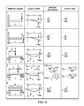
- FIG. 8 shows the beam deflection equations to show the ideal situation for building a wind correction device.
- FIG. 1 is a perspective view of a farm crop irrigation mechanism showing the mechanism in the form of a lateral or center pivot moving apparatus, and further showing two complete truss spans together with a portion of a third truss span. For simplicity sake, the scale and number of truss spans has been limited but will be understood to encompass numerous truss spans.
- FIG. 1 is a perspective view of a general irrigation device which moves in a linear or center pivot direction. The device provides a crop irrigation device for providing irrigation to fields while minimizing the labor requirements that are ordinarily necessary for such farming operations.
- the irrigation device includes mobile support towers 12 , 14 , and 16 .
- Each of the elongated truss spans 18 and 20 incorporate a water distribution conduit 22 .
- the water supply conduit 22 will include numerous sprinkler heads on a drop line 24 that are located in spaced relation along the entire length of the water distribution conduit.
- the water for irrigation is caused to flow through the irrigation conduit 20 under pressure, and as the water emerges from the irrigation heads, is sprinkled or sprayed onto the land area. Distribution of water onto the land is not limited to the sprinkling or spraying method illustrated herein.
- Each of the mobile support towers 12 , 14 , and 16 include a support framework structure (e.g., generally triangular) 32 , 34 and 36 having tower drive mechanisms 26 , 28 and 30 that include one or more drive motors 38 , 39 and 40 positioned at the lower extremity of the support framework structure 32 , 34 and 36 and providing motive power for controlled rotation of the drive wheels 42 , 43 and 44 .
- the respective drive wheels 42 , 43 and 44 and one or more drive motors 38 , 39 and 40 therefor are of reversible nature, and may be oriented in any suitable manner in relation to the support framework structure 32 , 34 and 36 , depending upon the particular design of the system involved.
- the drive motors 38 , 39 and 40 and drive wheels 42 , 43 and 44 are illustrated in one oriented and the respective truss spans may be oriented in any suitable manner so as to locate the respective conveyors in condition to convey the mobile support towers 12 , 14 , and 16 are elongated truss spans 18 and 20 either to or from the land or area being irrigated.
- the spaced support framework structure 32 , 34 and 36 may include other transverse braces or brace elements to support the elongated truss spans 18 and 20 .
- flexible inserts connect the adjacent water pipe mainline segments (not shown).
- the flexible inserts allow the water pipe mainline segments to maintain a fluid connection while allowing movement of the mobile support towers.
- the mobile support towers move independently and may have variations in the alignment due to variations in the position of the mobile support towers.
- FIG. 2 is a top view of the junction between adjacent water pipe mainline segments showing the motor controller.
- FIG. 3 is a side view of the junction between adjacent water pipe mainline segments showing the motor controller.
- the adjacent water pipe mainline segments 46 and 48 are coupled by a flexible insert 50 .
- the flexible inserts 50 is secured to the water pipe mainline 46 and 48 by a gasket 52 bolted in place to allow the non-uniformed movement of the adjacent water pipe mainline segments 46 and 48 .
- a motor controller 54 is positioned on the irrigation device 10 to control the direction and the duration of the operation of the one or more drive motors (not shown) positioned at the lower extremity of the support framework structure (not shown) to cause a motive power for controlled rotation of the drive wheels (not shown).
- the motor controller 54 functions as a forward/reverse limit switch so that there is one circuit for forward movement of the system and another, separate circuit, for reverse movement.
- the rotating shaft of the limit switch 56 has attached to it a slotted switch extension arm 64 which moves by means of a connecting rod 60 and an actuating arm 62 in accordance with any forward or backward misalignment of adjacent span sections. Regardless of whether the system is moving in a forward direction or reverse direction, when a tower falls behind or is misaligned, the shaft 56 of the switch on the adjacent towers rotate, causing the motors of the adjacent towers to stop until the lagging tower returns to the correct alignment. Once the correct alignment is reestablished, all of the motors of all the motorized towers are stopped.
- FIGS. 2 and 3 are for generic understanding only, the wind correction device is able to work on virtually any alignment system by applying a force, obtained from the wind, to the alignment linkage in such a manner that the linkage is strained such that the strain on the linkage counters the strain on the sprinkler span, such that overall alignment of the irrigation system is virtually not compromised by forces caused from the wind.
- FIGS. 4 a -4 i show schematics of the junction between the wind force capture geometry and the alignment linkage.
- FIG. 4 a shows one embodiment of the wind alignment mechanism of the present invention.
- the wind alignment mechanism 98 is mounted on the structural component 99 .
- a wind capture surface 100 is connected through extension rod 102 .
- the extension rod 102 is operably connected to the tower box 104 which includes or is connected to the motor controller.
- An angular connection rod 106 is perpendicularly connected to the extension rod 102 with tension mechanism 108 a and 108 b extending from the end of the angular connection rod 106 .
- the tension mechanism 108 a and 108 b each include a spring 110 a and 110 b prior to the attachment to the structural component 99 .
- the angular connection rod 106 is shown as connected perpendicularly any angle may be used to connect the angular connection rod to the extension rod 102 .
- FIG. 4 b shows one embodiment of the wind alignment mechanism of the present invention for a hydraulically driven system.
- the wind alignment mechanism 98 is mounted on the structural component 99 .
- a wind capture surface 100 is connected through extension rod 102 .
- the connection rod 102 is connected to the angular connection rod 106 through pivot 114 .
- the angular connection rod 106 is perpendicularly connected to the extension rod 102 but may be connected at any angle.
- the tension mechanism 108 a and 108 b are connected at one end to the tension mechanism connection device 116 a and 116 b and extend through guides 118 a and 118 b to connect to the extension rod 102 at connection 120 .
- a control valve 122 is connected to the tension mechanism 108 a and 108 b to detect the movement of the tension mechanism 108 a and 108 b which detects the movement of the extension rod 102 and wind capture surface 100 .
- the control valve 122 is in communication with the drive motors to actuate the drive motors.
- FIG. 4 c is a side view that shows one embodiment of the wind alignment mechanism of the present invention.
- the wind alignment mechanism 98 is mounted on the structural component 99 .
- a wind capture surface 100 is connected through extension rod 102 .
- the extension rod 102 is operably connected to the tower box 104 which includes or is connected to the motor controller by the angular connection rod 106 which is perpendicularly connected to the extension rod 102 .
- Pivot 114 is located on the extension rod 102 to allow the extension rod 102 to pivot as a result of the interaction of the capture surface 100 with the wind.
- FIG. 4 d is a top view that shows one embodiment of the wind alignment mechanism of the present invention.
- the wind alignment mechanism 98 is mounted on the structural component 99 .
- a wind capture surface 100 is connected through extension rod 102 .
- the extension rod 102 is operably connected to the tower box 104 which includes or is connected to the motor controller 54 (not shown) by the angular connection rod 106 which is perpendicularly connected to the extension rod 102 and includes extension rod 122 .
- Pivot 114 is located on the extension rod 102 to allow the extension rod 102 to pivot as a result of the interaction of the capture surface 100 with the wind.
- FIG. 4 e shows one embodiment of the wind alignment mechanism of the present invention.
- the wind alignment mechanism 98 is mounted on the structural component 99 .
- a wind capture surface 100 is connected through extension rod 102 and includes pivot 114 .
- the extension rod 102 is operably connected to the tower box 104 which includes or is connected to the motor controller.
- An angular connection rod 106 is perpendicularly connected to the extension rod 102 with tension mechanism 108 a and 108 b extending from the end of the angular connection rod 106 .
- the tension mechanism 108 a and 108 b each attach to the mechanism connection device 116 .
- the angular connection rod 106 is shown as connected perpendicularly any angle may be used to connect the angular connection rod to the extension rod 102 .
- FIG. 4 f shows one embodiment of the wind alignment mechanism of the present invention.
- the wind alignment mechanism 98 is mounted on the structural component 99 .
- a wind capture surface 100 is connected through extension rod 102 .
- the extension rod 102 is operably connected to the tower box 104 which includes or is connected to the motor controller by the angular connection rod 106 which is perpendicularly connected to the extension rod 102 .
- the extension rod 102 moves as a result of the interaction of the capture surface 100 with the wind.
- FIG. 4 g shows one embodiment of the wind alignment mechanism of the present invention.
- the wind alignment mechanism 98 is mounted on the structural component 99 .
- a wind capture surface 100 is connected through extension rod 102 .
- the extension rod 102 is operably connected to the tower box 104 which includes or is connected to the motor controller by the angular connection rod 106 which is perpendicularly connected to the extension rod 102 .
- the extension rod 102 moves as a result of the interaction of the capture surface 100 with the wind.
- FIG. 4 h is a side view that shows one embodiment of the wind alignment mechanism of the present invention.
- the wind alignment mechanism 98 is mounted on the structural component 99 .
- a wind capture surface 100 is connected through extension rod 102 .
- the extension rod 102 is operably connected to the tower box 104 which includes or is connected to the motor controller by the angular connection rod 106 which is perpendicularly connected to the extension rod 102 .
- Pivot 114 is located on the extension rod 102 to allow the extension rod 102 to pivot as a result of the interaction of the capture surface 100 with the wind.
- FIG. 4 i is a top view that shows one embodiment of the wind alignment mechanism of the present invention.
- the wind alignment mechanism 98 is mounted on the structural component 99 .
- a wind capture surface (not shown) is connected through extension rod 102 .
- the extension rod 102 is operably connected to the tower box 104 which includes or is connected to the motor controller by the angular connection rod 106 which is perpendicularly connected to the extension rod 102 .
- Pivot 114 is located on the extension rod 102 to allow the extension rod 102 to pivot as a result of the interaction of the capture surface (not shown) with the wind.
- FIGS. 5 a -5 n show schematics of the junction between the wind force capture geometry and the alignment linkage.
- the present invention is a wind adjustment device that takes into account the wind on the water pipe mainline segments and elongated truss spans located between the mobile support towers.
- the present invention provides a mechanism to adjust the position of the mobile support towers to offset the curvature induced from the force of the wind pushing against the water pipe mainline segments and elongated truss spans located between the mobile support towers.
- the present invention includes a wind detection device having a wind detection back surface and a wind detection front surface such that the wind can be detected in both the forward and backward direction.
- the wind detection device is of the size and shape to provide enough surface area for the wind to exhibit a force on the wind detection device.
- the wind detection device is in operable communication with the motor controller through the span alignment linkage. As a result, the wind detection device receives a force acting on it from the wind in a given direction, and as a result, moves the wind detection device in that direction. As the wind detection device moves it conveys a deflection that signals to the motor controller through the alignment linkage and activates the one or more drive motors as needed for correct alignment to move the mobile support towers.
- the repositioning of the mobile support towers results in a overall correction to the irrigation system.
- the water distribution conduit and elongated truss span straightening to remove the curvature induced by the force of the wind. The stronger the force of the find the stronger the signal to the motor controller and the more the movement of the mobile support towers by the one or more drive motors.
- the wind detection device is of the size and shape to provide enough surface area for the wind to exhibit a force on the wind detection device.
- Any geometric shape can be used to obtain a force from the wind blowing on the shape.
- the wind detection device may be a flat plate in a square, rectangular, circular, star, flag shape, Texas state outline, South Carolina state outline, free form or any other shape.
- 3 dimensional shapes can be used such as a sphere, pipe or other shape. The shape merely provides a surface to receive drag by the wind. As such it is irrelevant what the surface is only that it has the desired drag to allow movement in response to the direction of the wind.
- the force resulting on the shape of the wind detection back surface and a wind detection front surface from the perpendicular wind component on the system is then transferred to a member of the alignment linkage, thus causing a strain on the linkage which will result in a correction of alignment to the overall system.
- Any forces caused by the parallel component of the wind should not be transferred to the alignment linkage, or transferred in such a manner as to not affect the alignment.
- the force may be transferred, scaled and amplified as needed, to the linkage in any conventional manner, including but not limited to: pivoting linkage, cable, hydraulic, rotating shaft, or by directly mounting the geometric shape to the linkage.
- FIG. 8 shows the beam deflection equations to show the ideal situation for building a wind correction device.
- Loading example 6 can be used to simulate the wind load on each individual span. From this the slope at the end of the span is:
- compositions of the invention can be used to achieve methods of the invention.
- the words “comprising” (and any form of comprising, such as “comprise” and “comprises”), “having” (and any form of having, such as “have” and “has”), “including” (and any form of including, such as “includes” and “include”) or “containing” (and any form of containing, such as “contains” and “contain”) are inclusive or open-ended and do not exclude additional, unrecited elements or method steps.
- A, B, C, or combinations thereof refers to all permutations and combinations of the listed items preceding the term.
- “A, B, C, or combinations thereof” is intended to include at least one of: A, B, C, AB, AC, BC, or ABC, and if order is important in a particular context, also BA, CA, CB, CBA, BCA, ACB, BAC, or CAB.
- expressly included are combinations that contain repeats of one or more item or term, such as BB, AAA, AB, BBC, AAABCCCC, CBBAAA, CABABB, and so forth.
- BB BB
- AAA AAA
- AB BBC
- AAABCCCCCC CBBAAA
- CABABB CABABB
- compositions and/or methods disclosed and claimed herein can be made and executed without undue experimentation in light of the present disclosure. While the compositions and methods of this invention have been described in terms of preferred embodiments, it will be apparent to those of skill in the art that variations may be applied to the compositions and/or methods and in the steps or in the sequence of steps of the method described herein without departing from the concept, spirit and scope of the invention. All such similar substitutes and modifications apparent to those skilled in the art are deemed to be within the spirit, scope and concept of the invention as defined by the appended claims.
Landscapes
- Engineering & Computer Science (AREA)
- Water Supply & Treatment (AREA)
- Life Sciences & Earth Sciences (AREA)
- Environmental Sciences (AREA)
- Catching Or Destruction (AREA)
Abstract
Description
Since the alignment linkage is aligning 2 spans the linkage will see twice the slope at the end.
On any given system span, everything is a constant except for ω, therefore the slope is a direct linear function of ω, and the slope seen by the alignment linkage would be:
c1ω1
If the correction device places a force on the alignment linkage as in diagram 4, then we want the slope at the end to equal c1ω.
On any given alignment linkage, everything is a constant except for P, therefore we have:
c1ω=c2P2
The total force on the span is:
P1=ω1L1
From this we know that the force applied to the alignment linkage must be:
P2=cP1
The force on an object from the wind is:
P=CdAV2c
Where Cd is the drag coefficient, A is the cross sectional area, V is the wind speed, and c is a constant. As such, the geometric shape must only be designed such that the drag coefficient and cross sectional area provide a force such that:
P2=cP1
which is always a perfect match because everything is linear in all the equations except for the V2, which is a non-issue because both the system span and the geometric shape will always see the same velocity.
Claims (12)
Priority Applications (1)
| Application Number | Priority Date | Filing Date | Title |
|---|---|---|---|
| US15/186,090 US10342186B2 (en) | 2015-06-18 | 2016-06-17 | Mechanism for aligning irrigation systems used for farm crops |
Applications Claiming Priority (2)
| Application Number | Priority Date | Filing Date | Title |
|---|---|---|---|
| US201562181360P | 2015-06-18 | 2015-06-18 | |
| US15/186,090 US10342186B2 (en) | 2015-06-18 | 2016-06-17 | Mechanism for aligning irrigation systems used for farm crops |
Publications (2)
| Publication Number | Publication Date |
|---|---|
| US20160366840A1 US20160366840A1 (en) | 2016-12-22 |
| US10342186B2 true US10342186B2 (en) | 2019-07-09 |
Family
ID=57586740
Family Applications (1)
| Application Number | Title | Priority Date | Filing Date |
|---|---|---|---|
| US15/186,090 Expired - Fee Related US10342186B2 (en) | 2015-06-18 | 2016-06-17 | Mechanism for aligning irrigation systems used for farm crops |
Country Status (1)
| Country | Link |
|---|---|
| US (1) | US10342186B2 (en) |
Cited By (2)
| Publication number | Priority date | Publication date | Assignee | Title |
|---|---|---|---|---|
| US12310298B2 (en) | 2022-02-03 | 2025-05-27 | Lindsay Corporation | Alignment guide for an alignment system of a mobile irrigation system |
| US12408602B2 (en) | 2022-02-02 | 2025-09-09 | Lindsay Corporation | Alignment system for a mobile irrigation system |
Families Citing this family (2)
| Publication number | Priority date | Publication date | Assignee | Title |
|---|---|---|---|---|
| US10070597B2 (en) * | 2015-10-20 | 2018-09-11 | Precision Circle, LLC | Method to cycle the drive motors of an irrigation system |
| CN107691199B (en) * | 2017-12-10 | 2020-05-22 | 蓝全杰 | Agricultural is grown seedlings with convenient device that waters |
Citations (8)
| Publication number | Priority date | Publication date | Assignee | Title |
|---|---|---|---|---|
| US4172551A (en) * | 1977-11-29 | 1979-10-30 | Valmont Industries, Inc. | Linear move irrigation system and control therefor |
| EP0040828A1 (en) | 1980-05-23 | 1981-12-02 | Pick-Pro International Industries, Ltd. | Mechanism for irrigation, maintenance and harvesting of farm crops |
| US6755362B2 (en) * | 2001-10-04 | 2004-06-29 | Neal Krieger | Irrigation system with variable speed drive system |
| US20130008977A1 (en) * | 2011-07-05 | 2013-01-10 | Lindsay Corporation | System and method for controlling operation of an irrigation system end gun |
| US20130090772A1 (en) * | 2011-10-06 | 2013-04-11 | Lindsay Corporation | Method and system for orienting an irrigation system to minimize wind damage |
| US8777133B2 (en) * | 2009-12-01 | 2014-07-15 | Lindsay Corporation | Irrigation system for small fields |
| US20140371971A1 (en) * | 2013-06-18 | 2014-12-18 | Lindsay Corporation | Single wheel irrigation tower |
| US9101097B2 (en) * | 2011-08-09 | 2015-08-11 | Valmont Industries, Inc. | Harvesting machine |
-
2016
- 2016-06-17 US US15/186,090 patent/US10342186B2/en not_active Expired - Fee Related
Patent Citations (8)
| Publication number | Priority date | Publication date | Assignee | Title |
|---|---|---|---|---|
| US4172551A (en) * | 1977-11-29 | 1979-10-30 | Valmont Industries, Inc. | Linear move irrigation system and control therefor |
| EP0040828A1 (en) | 1980-05-23 | 1981-12-02 | Pick-Pro International Industries, Ltd. | Mechanism for irrigation, maintenance and harvesting of farm crops |
| US6755362B2 (en) * | 2001-10-04 | 2004-06-29 | Neal Krieger | Irrigation system with variable speed drive system |
| US8777133B2 (en) * | 2009-12-01 | 2014-07-15 | Lindsay Corporation | Irrigation system for small fields |
| US20130008977A1 (en) * | 2011-07-05 | 2013-01-10 | Lindsay Corporation | System and method for controlling operation of an irrigation system end gun |
| US9101097B2 (en) * | 2011-08-09 | 2015-08-11 | Valmont Industries, Inc. | Harvesting machine |
| US20130090772A1 (en) * | 2011-10-06 | 2013-04-11 | Lindsay Corporation | Method and system for orienting an irrigation system to minimize wind damage |
| US20140371971A1 (en) * | 2013-06-18 | 2014-12-18 | Lindsay Corporation | Single wheel irrigation tower |
Cited By (2)
| Publication number | Priority date | Publication date | Assignee | Title |
|---|---|---|---|---|
| US12408602B2 (en) | 2022-02-02 | 2025-09-09 | Lindsay Corporation | Alignment system for a mobile irrigation system |
| US12310298B2 (en) | 2022-02-03 | 2025-05-27 | Lindsay Corporation | Alignment guide for an alignment system of a mobile irrigation system |
Also Published As
| Publication number | Publication date |
|---|---|
| US20160366840A1 (en) | 2016-12-22 |
Similar Documents
| Publication | Publication Date | Title |
|---|---|---|
| US10342186B2 (en) | Mechanism for aligning irrigation systems used for farm crops | |
| US9342076B2 (en) | Adjustable speed irrigation system and method of use | |
| US3628729A (en) | Mobile irrigation apparatus | |
| US10231390B2 (en) | Irrigation system with variable gear ratio transmissions | |
| EP2441321A2 (en) | Agricultural device to support and handle different operating units adapted to work on rows located on flat lands or hills | |
| US9101097B2 (en) | Harvesting machine | |
| AU3251200A (en) | A corner irrigation system | |
| US2988287A (en) | Boom sprinkler with wind responsive means | |
| US20250268159A1 (en) | Expandable pivot irrigation system | |
| RU163954U1 (en) | WIDE CAPPING RAINING MACHINE | |
| CN206994181U (en) | A kind of spray rod system | |
| US3583428A (en) | Laterally moving automatic irrigation system | |
| RU2729823C1 (en) | Sprinkler device for positional action | |
| US20110017850A1 (en) | Irrigation method, apparatus and system | |
| US3536261A (en) | Sprinkler irrigation device | |
| US8317114B1 (en) | Dual span center pivot irrigation system | |
| EP3782450A1 (en) | Fertiliser machine for a grove of trees | |
| US9677242B2 (en) | Method and apparatus for anchoring an irrigation drive assembly | |
| EP3939426B1 (en) | Agricultural device for spreading a pumpable medium over agricultural land using a spreader arm and method of adjusting a working width of a vehicle provided with such an agricultural device | |
| WO2002026026A1 (en) | Device for applying agrochemicals that can be installed on a mobile structure | |
| US9242257B2 (en) | Variable nozzle assembly | |
| EP1830625B1 (en) | Liquid application system for center pivot irrigation system | |
| CN107396778A (en) | Greenhouse water-saving spray irrigation system | |
| RU2317153C1 (en) | Sprinkler head | |
| RU2130251C1 (en) | Boom-type sprinkler unit |
Legal Events
| Date | Code | Title | Description |
|---|---|---|---|
| STCB | Information on status: application discontinuation |
Free format text: ABANDONMENT FOR FAILURE TO CORRECT DRAWINGS/OATH/NONPUB REQUEST |
|
| STPP | Information on status: patent application and granting procedure in general |
Free format text: PUBLICATIONS -- ISSUE FEE PAYMENT VERIFIED |
|
| STCF | Information on status: patent grant |
Free format text: PATENTED CASE |
|
| FEPP | Fee payment procedure |
Free format text: MAINTENANCE FEE REMINDER MAILED (ORIGINAL EVENT CODE: REM.); ENTITY STATUS OF PATENT OWNER: SMALL ENTITY |
|
| LAPS | Lapse for failure to pay maintenance fees |
Free format text: PATENT EXPIRED FOR FAILURE TO PAY MAINTENANCE FEES (ORIGINAL EVENT CODE: EXP.); ENTITY STATUS OF PATENT OWNER: SMALL ENTITY |
|
| STCH | Information on status: patent discontinuation |
Free format text: PATENT EXPIRED DUE TO NONPAYMENT OF MAINTENANCE FEES UNDER 37 CFR 1.362 |
|
| FP | Lapsed due to failure to pay maintenance fee |
Effective date: 20230709 |