US10329874B2 - Safety valve handling apparatus for a well operation rig - Google Patents
Safety valve handling apparatus for a well operation rig Download PDFInfo
- Publication number
- US10329874B2 US10329874B2 US15/383,834 US201615383834A US10329874B2 US 10329874 B2 US10329874 B2 US 10329874B2 US 201615383834 A US201615383834 A US 201615383834A US 10329874 B2 US10329874 B2 US 10329874B2
- Authority
- US
- United States
- Prior art keywords
- safety valve
- main mount
- mount tube
- clamp
- rig
- Prior art date
- Legal status (The legal status is an assumption and is not a legal conclusion. Google has not performed a legal analysis and makes no representation as to the accuracy of the status listed.)
- Active, expires
Links
- 230000005484 gravity Effects 0.000 claims description 3
- 230000008878 coupling Effects 0.000 claims 2
- 238000010168 coupling process Methods 0.000 claims 2
- 238000005859 coupling reaction Methods 0.000 claims 2
- 238000005553 drilling Methods 0.000 description 3
- 230000004048 modification Effects 0.000 description 2
- 238000012986 modification Methods 0.000 description 2
- 239000012530 fluid Substances 0.000 description 1
- 238000009434 installation Methods 0.000 description 1
- 238000004519 manufacturing process Methods 0.000 description 1
Images


Classifications
-
- E—FIXED CONSTRUCTIONS
- E21—EARTH OR ROCK DRILLING; MINING
- E21B—EARTH OR ROCK DRILLING; OBTAINING OIL, GAS, WATER, SOLUBLE OR MELTABLE MATERIALS OR A SLURRY OF MINERALS FROM WELLS
- E21B34/00—Valve arrangements for boreholes or wells
-
- E—FIXED CONSTRUCTIONS
- E21—EARTH OR ROCK DRILLING; MINING
- E21B—EARTH OR ROCK DRILLING; OBTAINING OIL, GAS, WATER, SOLUBLE OR MELTABLE MATERIALS OR A SLURRY OF MINERALS FROM WELLS
- E21B15/00—Supports for the drilling machine, e.g. derricks or masts
-
- E—FIXED CONSTRUCTIONS
- E21—EARTH OR ROCK DRILLING; MINING
- E21B—EARTH OR ROCK DRILLING; OBTAINING OIL, GAS, WATER, SOLUBLE OR MELTABLE MATERIALS OR A SLURRY OF MINERALS FROM WELLS
- E21B19/00—Handling rods, casings, tubes or the like outside the borehole, e.g. in the derrick; Apparatus for feeding the rods or cables
- E21B19/02—Rod or cable suspensions
-
- E—FIXED CONSTRUCTIONS
- E21—EARTH OR ROCK DRILLING; MINING
- E21B—EARTH OR ROCK DRILLING; OBTAINING OIL, GAS, WATER, SOLUBLE OR MELTABLE MATERIALS OR A SLURRY OF MINERALS FROM WELLS
- E21B19/00—Handling rods, casings, tubes or the like outside the borehole, e.g. in the derrick; Apparatus for feeding the rods or cables
- E21B19/16—Connecting or disconnecting pipe couplings or joints
-
- E—FIXED CONSTRUCTIONS
- E21—EARTH OR ROCK DRILLING; MINING
- E21B—EARTH OR ROCK DRILLING; OBTAINING OIL, GAS, WATER, SOLUBLE OR MELTABLE MATERIALS OR A SLURRY OF MINERALS FROM WELLS
- E21B21/00—Methods or apparatus for flushing boreholes, e.g. by use of exhaust air from motor
- E21B21/10—Valve arrangements in drilling-fluid circulation systems
Definitions
- the invention relates to a well operation rig apparatus and in particular a safety valve apparatus.
- Pipe strings sometimes called drill, production or work strings, each used for drilling and/or servicing.
- the pipe string can comprise a bottom hole assembly such as, when drilling, a drill bit attached to sections of drill pipe.
- additional sections of drill pipe are added to the pipe string to extend its length until the bottom hole assembly is deep enough to reach a depth of interest.
- Sections of pipe are joined together using threaded connections on the pipe, often referred to as “pin” and “box” connections, where the pin of one section of pipe is threaded into the box of an adjoining section of pipe.
- the sections of pipe can be removed from the pipe string by unthreading the connections and setting aside a pipe section.
- one section of pipe is secured protruding from the rig floor. This section is often referred to as the stump.
- the stump may have an open inner diameter that is in communication with the bottom hole assembly in the depths of the well.
- a plug may be installed to stop fluids from passing up through the string and from being released at the stump.
- a plug may be installed if there is a stoppage in the drilling or servicing operation.
- the plug used for installation in the stump is called a safety valve or a stabbing valve.
- the safety valve has a threaded connection that threads into the stump's exposed threaded connection and an integral valve that can be opened or closed to open the inner diameter of the pipe string at the stump.
- the safety valve must be kept at the ready.
- the safety valve is set on the rig work floor and must be manually lifted into place or the safety valve is suspended from a tugger winch and must be hoisted into position if needed.
- a safety valve handling apparatus for a rig, the apparatus comprising: a mounting structure for connection to the rig; a clamp for engaging a safety valve and configured to permit rotation of the safety valve within the clamp while the safety valve remains engaged by the clamp; and an arm connected between the mounting structure and the clamp, the arm being movable and adjustable to permit movement of the clamp relative to the mounting structure.
- a well operation rig comprising: a mast; a safety valve for securing in a stump secured by the well operation rig; a safety valve apparatus for installing the safety valve on the mast, the safety valve comprising: a mounting structure for connecting the apparatus to mast; a clamp for engaging the safety valve and configured to permit rotation of the safety valve within the clamp while the safety valve remains engaged by the clamp; and an arm connected between the mounting structure and the clamp, the arm being movable and adjustable to permit movement of the clamp relative to the mounting structure.
- FIG. 1 is a front perspective view of a safety valve handling apparatus holding a safety valve
- FIG. 2 is an exploded view of the of the safety valve handling apparatus of FIG. 1 ;
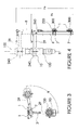
- FIG. 3 is a top view showing movement of the swing arm
- FIG. 4 is a side elevation showing movement of the main mount tube.
- a safety valve 100 is shown being supported by a safety valve handling apparatus 200 .
- a safety valve may take various configurations but generally includes a body with a generally cylindrical outer surface 112 about a long axis x and a lower end with a threaded connection 114 sized and configured to thread into the threaded connection used to connect one pipe section to the next.
- the threaded connection on the safety valve is most likely a pin, as shown, configured to thread into a box.
- Safety valve apparatus 200 holds safety valve 100 adjacent the rig's 300 mast height axis which aligns with well center WC, where the stump 310 emerges from the rig floor. As such, apparatus 200 supports valve 100 in a position ready to be installed.
- Apparatus 200 is configured to:
- FIGS. 1 to 4 show one embodiment of safety valve apparatus 200 .
- safety valve apparatus 200 includes a mounting structure 220 , a clamp 240 for engaging the safety valve apparatus and a movable arm 260 connected at one end to the mounting structure 220 and connected at the other end to the clamp.
- Mounting structure 220 is configured to secure arm 260 and thereby safety valve 100 in a position on the rig.
- Mounting structure 220 may be permanent or releasable and may be configured in many possible ways.
- structure 220 includes brackets 1 , 7 , 14 and fasteners 16 for attachment to a portion of the rig.
- the brackets 1 , 14 are intended to work with a frame that includes a pair of cylindrical mounting rails that fit within the cylindrical bores 1 a in brackets 1 .
- other bracket configurations are possible.
- Mounting structure 220 mounts the base of arm 260 in a fixed position, for example, parallel to the mast height axis. Structure 220 moves with the rig such that if the rig is vertical the mounting structure is vertical. If the rig WC is on a slant the mounting structure is on a similar slant. The mounting structure moves the arm accordingly with the rig.
- Arm 260 is adjustable with respect to both height and angular extension such that the position of the clamp 240 , which is on the upper end of arm, can be adjustable.
- Arm 260 includes main mount tube including an outer mount tube 6 and an inner support tube 8 . Together tube 6 and 8 provide for vertical movement and adjustment of the clamp. In particular, tube 6 can telescopically slide relative to, for example from within, tube 8 to adjust for height of the clamp relative to the brackets 1 , 7 .
- a gas spring 2 is provided as a movement control mechanism, to control relative movement of the tubes 6 , 8 .
- the gas spring may bias the tubes 6 , 8 into an extended position, for example at a maximum extended height H E .
- the gas spring bias urges the main mount tube into an elevated position such that it can be swung over hole center in a position above the stump and then a force can be applied to lower the apparatus to a lower height H L , to and thereby allows safety valve 100 to be threaded into the stump.
- the elevated position is shown in phantom while the lower position is shown in solid lines. The force is sufficient to force gas spring 2 to compress and thereby shorten the main mount tube and lower the swing arm.
- arm 260 also includes a swing arm 29 extending at substantially a right angle from the long axis of the main mount tube. Swing arm 29 is configured to rotate through an angle ⁇ relative to the long axis of the mount tube.
- the swing arm is connected to inner support tube 8 via a pivotal connection 30 .
- a gas spring 3 is provided to control movement of the swing arm through angle x relative to the mount tube.
- Gas spring 3 may, for example, resist uncontrolled movement of swing arm 29 such as when it is placed in slant.
- gas spring 3 acts like a releasable position lock and may be selected to ease movement into well center and to resist movement of the swing arm from swinging uncontrollably with gravity when the mount tube is moved out of a vertical orientation.
- the clamp 240 is configured to both hold the safety valve on the arm and to permit rotation of the safety valve about its long axis x.
- Clamp 240 may include for example a clamping portion 10 that encircles the safety valve body and a bearing 13 that is rotatable within clamping portion and thereby permits safety valve 100 to rotate within portion 10 .
- clamping portion 10 is a split clamp with halves connected at one side by a hinge 18 and releasably connected at the other side by a releasable lock such as including a removable lock pin 5 securable through alignable barrels.
- bearing 13 includes a split bushing securable by, for example, fasteners 26 about the safety valve.
- the ring is rigidly secured about surface 112 , but fits, is axially fixed and can rotate within an annular groove formed on the inside of portion 10 , when its halves are secured about the ring.
- the annular groove is formed by a groove portion 9 on the interior surface of each half of the clamping portion.
- the function of the stabbing valve apparatus is to hold safety valve 100 adjacent well center and to be movable and adjustable such that the safety valve can be moved from a storage position into a position over, for example, with a concentric center point of clamping portion 10 aligned with well center.
- the apparatus allows a person to secure the well by lowering the safety valve into a stump and manually tightening the connection between end 114 and the stumps threaded box connection.
- the safety valve remains supported on the apparatus, but the safety valve can be rotated within the clamp of the apparatus, by rotating the ring of bearing 13 within the annular recess 9 within the clamping portion 10 .
- the clamp allows for quick changes of safety valves but when made up holds the safety valves securely but while allowing for rotation of the safety valve for threading.
- the apparatus mounts to the rig structure 300 , for example, through a torque wrench frame.
- the mount tube permits vertical positioning and the swing arm permits rotational positioning with controls by releasable locks such as gas springs.
- the apparatus can be moved and maintained in a storage position away from well center but then can be moved and adjusted readily to move the safety valve into well center and may be threaded into a stump regardless of the height of the stump or whether the rig is vertical or on a slant.
- the apparatus provides a reliable, easy and relatively safe option for storing, handling and threading a safety valve into a stump to secure the well.
Landscapes
- Engineering & Computer Science (AREA)
- Geology (AREA)
- Life Sciences & Earth Sciences (AREA)
- Mining & Mineral Resources (AREA)
- Environmental & Geological Engineering (AREA)
- Fluid Mechanics (AREA)
- Physics & Mathematics (AREA)
- General Life Sciences & Earth Sciences (AREA)
- Geochemistry & Mineralogy (AREA)
- Mechanical Engineering (AREA)
- Filling Or Discharging Of Gas Storage Vessels (AREA)
- Earth Drilling (AREA)
- Mutual Connection Of Rods And Tubes (AREA)
- Pivots And Pivotal Connections (AREA)
Abstract
Description
-
- i. be mountable on the rig structure adjacent well center;
- ii. hold
safety valve 100 while permitting rotation of it about its long axis x. As such, the safety valve can be threaded into a stump while remaining secured to the rig; and/or - iii. be movable and adjustable to allow long axis x of
safety valve 100 to be moved into and out of alignment with well center while both the apparatus and safety valve remain secured to the rig.
Claims (14)
Priority Applications (1)
| Application Number | Priority Date | Filing Date | Title |
|---|---|---|---|
| US15/383,834 US10329874B2 (en) | 2016-02-18 | 2016-12-19 | Safety valve handling apparatus for a well operation rig |
Applications Claiming Priority (2)
| Application Number | Priority Date | Filing Date | Title |
|---|---|---|---|
| US201662296719P | 2016-02-18 | 2016-02-18 | |
| US15/383,834 US10329874B2 (en) | 2016-02-18 | 2016-12-19 | Safety valve handling apparatus for a well operation rig |
Publications (2)
| Publication Number | Publication Date |
|---|---|
| US20170241234A1 US20170241234A1 (en) | 2017-08-24 |
| US10329874B2 true US10329874B2 (en) | 2019-06-25 |
Family
ID=59593728
Family Applications (1)
| Application Number | Title | Priority Date | Filing Date |
|---|---|---|---|
| US15/383,834 Active 2037-02-21 US10329874B2 (en) | 2016-02-18 | 2016-12-19 | Safety valve handling apparatus for a well operation rig |
Country Status (2)
| Country | Link |
|---|---|
| US (1) | US10329874B2 (en) |
| CA (1) | CA2952071C (en) |
Cited By (1)
| Publication number | Priority date | Publication date | Assignee | Title |
|---|---|---|---|---|
| US11236554B2 (en) * | 2017-10-10 | 2022-02-01 | Tuttie's Machine & Supply, Inc. | Well servicing lift apparatus |
Families Citing this family (1)
| Publication number | Priority date | Publication date | Assignee | Title |
|---|---|---|---|---|
| US10225065B2 (en) * | 2015-12-18 | 2019-03-05 | Qualcomm Incorporated | Common control channel subband design and signaling |
Citations (4)
| Publication number | Priority date | Publication date | Assignee | Title |
|---|---|---|---|---|
| US2976943A (en) * | 1957-11-13 | 1961-03-28 | Joy Mfg Co | Device for use in uncoupling drill steels |
| US6189620B1 (en) * | 2000-07-31 | 2001-02-20 | Mcdowell Bobby Dewain | Method and apparatus for shutting off upward flow from a conduit |
| US20130255446A1 (en) * | 2012-04-03 | 2013-10-03 | Rangeland Industrial Service Ltd. | Power tong apparatus |
| US20170175463A1 (en) * | 2015-12-22 | 2017-06-22 | Bly Ip Inc. | Drill rod clamping system and methods of using same |
-
2016
- 2016-12-15 CA CA2952071A patent/CA2952071C/en active Active
- 2016-12-19 US US15/383,834 patent/US10329874B2/en active Active
Patent Citations (4)
| Publication number | Priority date | Publication date | Assignee | Title |
|---|---|---|---|---|
| US2976943A (en) * | 1957-11-13 | 1961-03-28 | Joy Mfg Co | Device for use in uncoupling drill steels |
| US6189620B1 (en) * | 2000-07-31 | 2001-02-20 | Mcdowell Bobby Dewain | Method and apparatus for shutting off upward flow from a conduit |
| US20130255446A1 (en) * | 2012-04-03 | 2013-10-03 | Rangeland Industrial Service Ltd. | Power tong apparatus |
| US20170175463A1 (en) * | 2015-12-22 | 2017-06-22 | Bly Ip Inc. | Drill rod clamping system and methods of using same |
Cited By (1)
| Publication number | Priority date | Publication date | Assignee | Title |
|---|---|---|---|---|
| US11236554B2 (en) * | 2017-10-10 | 2022-02-01 | Tuttie's Machine & Supply, Inc. | Well servicing lift apparatus |
Also Published As
| Publication number | Publication date |
|---|---|
| CA2952071A1 (en) | 2017-08-18 |
| US20170241234A1 (en) | 2017-08-24 |
| CA2952071C (en) | 2024-01-02 |
Similar Documents
| Publication | Publication Date | Title |
|---|---|---|
| US6994176B2 (en) | Adjustable rotating guides for spider or elevator | |
| US4035012A (en) | Dual elevators | |
| US7770654B2 (en) | Pipe handling device, method and system | |
| US7370707B2 (en) | Method and apparatus for handling wellbore tubulars | |
| US20090053014A1 (en) | Apparatus for an automatic casing stabbing arm | |
| US7992909B2 (en) | Single joint elevator with jaws secured by a powered door | |
| CN101611215A (en) | Top drive apparatus and method for gripping tubulars | |
| US20040216890A1 (en) | Tong positioning system and method | |
| CA2805697C (en) | Tubing apparatus and associated methods | |
| WO2010135823A1 (en) | Casing stabbing guide | |
| US11591862B2 (en) | External trap apparatus and method for safely controlling tool string assemblies | |
| US10760356B2 (en) | Drill pipe guide system and method | |
| CA3008007C (en) | Torque wrench | |
| US10329874B2 (en) | Safety valve handling apparatus for a well operation rig | |
| GB2484192A (en) | Running tool with hoist | |
| US9140078B2 (en) | Extended range single-joint elevator | |
| NO20140608A1 (en) | Adjustable rotatable guide devices for spider or elevator | |
| CN101094965A (en) | Apparatus and method for guiding pipe | |
| US20140110135A1 (en) | Method and Apparatus for Elevator Hobble Compensation | |
| US10822889B2 (en) | Load transfer system for stands of tubulars | |
| EP3177799B1 (en) | Extended range single-joint elevator | |
| US20130341088A1 (en) | Apparatus associated with sub-sea operations | |
| US9759019B2 (en) | Tubular joint elevator and method | |
| BRPI0412221B1 (en) | combination of a subsea terminal system with a production member and a pipe suspender and subsea terminal system | |
| US9404325B2 (en) | Drill bit driver |
Legal Events
| Date | Code | Title | Description |
|---|---|---|---|
| AS | Assignment |
Owner name: PROSTAR MANUFACTURING INC., CANADA Free format text: ASSIGNMENT OF ASSIGNORS INTEREST;ASSIGNORS:WRIGHT, ADAM;KUSLER, DANIEL HARVARD;REEL/FRAME:040674/0089 Effective date: 20161207 |
|
| AS | Assignment |
Owner name: PROSTAR MANUFACTURING INC., CANADA Free format text: ASSIGNMENT OF ASSIGNORS INTEREST;ASSIGNORS:WRIGHT, ADAM;KUSLER, DANIEL HARVARD;REEL/FRAME:043077/0048 Effective date: 20161207 |
|
| AS | Assignment |
Owner name: PROSTAR ENERGY TECHNOLOGIES (USA) LLC, CANADA Free format text: ASSIGNMENT OF ASSIGNORS INTEREST;ASSIGNOR:PROSTAR MANUFACTURING INC.;REEL/FRAME:048015/0708 Effective date: 20181221 |
|
| STPP | Information on status: patent application and granting procedure in general |
Free format text: NOTICE OF ALLOWANCE MAILED -- APPLICATION RECEIVED IN OFFICE OF PUBLICATIONS |
|
| STPP | Information on status: patent application and granting procedure in general |
Free format text: PUBLICATIONS -- ISSUE FEE PAYMENT VERIFIED |
|
| STCF | Information on status: patent grant |
Free format text: PATENTED CASE |
|
| MAFP | Maintenance fee payment |
Free format text: PAYMENT OF MAINTENANCE FEE, 4TH YR, SMALL ENTITY (ORIGINAL EVENT CODE: M2551); ENTITY STATUS OF PATENT OWNER: SMALL ENTITY Year of fee payment: 4 |