US10328267B2 - Methods for constructing posture calibration matrices - Google Patents
Methods for constructing posture calibration matrices Download PDFInfo
- Publication number
- US10328267B2 US10328267B2 US13/024,823 US201113024823A US10328267B2 US 10328267 B2 US10328267 B2 US 10328267B2 US 201113024823 A US201113024823 A US 201113024823A US 10328267 B2 US10328267 B2 US 10328267B2
- Authority
- US
- United States
- Prior art keywords
- posture
- sensor
- sensor output
- matrix
- calculating
- Prior art date
- Legal status (The legal status is an assumption and is not a legal conclusion. Google has not performed a legal analysis and makes no representation as to the accuracy of the status listed.)
- Active, expires
Links
- 238000000034 method Methods 0.000 title claims description 36
- 230000009466 transformation Effects 0.000 claims abstract description 58
- 238000000844 transformation Methods 0.000 claims abstract description 18
- 239000011159 matrix material Substances 0.000 claims description 148
- 230000001131 transforming effect Effects 0.000 claims description 11
- 230000008569 process Effects 0.000 claims description 5
- 230000036544 posture Effects 0.000 description 224
- 238000004364 calculation method Methods 0.000 description 13
- 230000006870 function Effects 0.000 description 12
- 238000005259 measurement Methods 0.000 description 12
- 230000000747 cardiac effect Effects 0.000 description 9
- 238000012544 monitoring process Methods 0.000 description 9
- 238000002560 therapeutic procedure Methods 0.000 description 9
- 230000014509 gene expression Effects 0.000 description 7
- 230000005484 gravity Effects 0.000 description 7
- 230000029058 respiratory gaseous exchange Effects 0.000 description 7
- 238000010586 diagram Methods 0.000 description 6
- 206010019280 Heart failures Diseases 0.000 description 4
- 238000009125 cardiac resynchronization therapy Methods 0.000 description 4
- 208000019622 heart disease Diseases 0.000 description 4
- 210000002620 vena cava superior Anatomy 0.000 description 4
- 230000002861 ventricular Effects 0.000 description 4
- 230000004872 arterial blood pressure Effects 0.000 description 3
- 230000001746 atrial effect Effects 0.000 description 3
- 238000013194 cardioversion Methods 0.000 description 3
- 210000003748 coronary sinus Anatomy 0.000 description 3
- 201000010099 disease Diseases 0.000 description 3
- 208000037265 diseases, disorders, signs and symptoms Diseases 0.000 description 3
- 230000000694 effects Effects 0.000 description 3
- 210000005240 left ventricle Anatomy 0.000 description 3
- 238000007726 management method Methods 0.000 description 3
- 230000015654 memory Effects 0.000 description 3
- 210000005241 right ventricle Anatomy 0.000 description 3
- 208000020446 Cardiac disease Diseases 0.000 description 2
- 206010007559 Cardiac failure congestive Diseases 0.000 description 2
- 206010013974 Dyspnoea paroxysmal nocturnal Diseases 0.000 description 2
- 206010020772 Hypertension Diseases 0.000 description 2
- 208000001953 Hypotension Diseases 0.000 description 2
- 206010031123 Orthopnoea Diseases 0.000 description 2
- 208000004327 Paroxysmal Dyspnea Diseases 0.000 description 2
- 210000003484 anatomy Anatomy 0.000 description 2
- 238000013459 approach Methods 0.000 description 2
- 238000004891 communication Methods 0.000 description 2
- 210000002837 heart atrium Anatomy 0.000 description 2
- 238000007689 inspection Methods 0.000 description 2
- 208000012866 low blood pressure Diseases 0.000 description 2
- 208000012144 orthopnea Diseases 0.000 description 2
- 238000012545 processing Methods 0.000 description 2
- 230000002685 pulmonary effect Effects 0.000 description 2
- 210000005245 right atrium Anatomy 0.000 description 2
- 238000002633 shock therapy Methods 0.000 description 2
- 238000007920 subcutaneous administration Methods 0.000 description 2
- 210000003462 vein Anatomy 0.000 description 2
- 208000036829 Device dislocation Diseases 0.000 description 1
- 102100026827 Protein associated with UVRAG as autophagy enhancer Human genes 0.000 description 1
- 101710102978 Protein associated with UVRAG as autophagy enhancer Proteins 0.000 description 1
- 230000001133 acceleration Effects 0.000 description 1
- 230000003044 adaptive effect Effects 0.000 description 1
- 230000008901 benefit Effects 0.000 description 1
- 239000008280 blood Substances 0.000 description 1
- 210000004369 blood Anatomy 0.000 description 1
- 230000000295 complement effect Effects 0.000 description 1
- 238000004590 computer program Methods 0.000 description 1
- 230000008878 coupling Effects 0.000 description 1
- 238000010168 coupling process Methods 0.000 description 1
- 238000005859 coupling reaction Methods 0.000 description 1
- 238000003745 diagnosis Methods 0.000 description 1
- 238000012377 drug delivery Methods 0.000 description 1
- 238000009472 formulation Methods 0.000 description 1
- 230000004217 heart function Effects 0.000 description 1
- 238000003780 insertion Methods 0.000 description 1
- 230000037431 insertion Effects 0.000 description 1
- 210000005246 left atrium Anatomy 0.000 description 1
- 210000004072 lung Anatomy 0.000 description 1
- 230000028161 membrane depolarization Effects 0.000 description 1
- 238000013508 migration Methods 0.000 description 1
- 230000005012 migration Effects 0.000 description 1
- 239000000203 mixture Substances 0.000 description 1
- 210000004165 myocardium Anatomy 0.000 description 1
- 230000001537 neural effect Effects 0.000 description 1
- 230000003287 optical effect Effects 0.000 description 1
- 230000035479 physiological effects, processes and functions Effects 0.000 description 1
- 210000001147 pulmonary artery Anatomy 0.000 description 1
- 210000003102 pulmonary valve Anatomy 0.000 description 1
- 230000000284 resting effect Effects 0.000 description 1
- 230000033764 rhythmic process Effects 0.000 description 1
- 230000000638 stimulation Effects 0.000 description 1
- 230000001225 therapeutic effect Effects 0.000 description 1
Images


Classifications
-
- A—HUMAN NECESSITIES
- A61—MEDICAL OR VETERINARY SCIENCE; HYGIENE
- A61N—ELECTROTHERAPY; MAGNETOTHERAPY; RADIATION THERAPY; ULTRASOUND THERAPY
- A61N1/00—Electrotherapy; Circuits therefor
- A61N1/18—Applying electric currents by contact electrodes
- A61N1/32—Applying electric currents by contact electrodes alternating or intermittent currents
- A61N1/36—Applying electric currents by contact electrodes alternating or intermittent currents for stimulation
- A61N1/362—Heart stimulators
- A61N1/365—Heart stimulators controlled by a physiological parameter, e.g. heart potential
- A61N1/36514—Heart stimulators controlled by a physiological parameter, e.g. heart potential controlled by a physiological quantity other than heart potential, e.g. blood pressure
- A61N1/36542—Heart stimulators controlled by a physiological parameter, e.g. heart potential controlled by a physiological quantity other than heart potential, e.g. blood pressure controlled by body motion, e.g. acceleration
-
- A—HUMAN NECESSITIES
- A61—MEDICAL OR VETERINARY SCIENCE; HYGIENE
- A61B—DIAGNOSIS; SURGERY; IDENTIFICATION
- A61B5/00—Measuring for diagnostic purposes; Identification of persons
- A61B5/103—Measuring devices for testing the shape, pattern, colour, size or movement of the body or parts thereof, for diagnostic purposes
- A61B5/11—Measuring movement of the entire body or parts thereof, e.g. head or hand tremor or mobility of a limb
- A61B5/1116—Determining posture transitions
- A61B5/1117—Fall detection
-
- A—HUMAN NECESSITIES
- A61—MEDICAL OR VETERINARY SCIENCE; HYGIENE
- A61B—DIAGNOSIS; SURGERY; IDENTIFICATION
- A61B5/00—Measuring for diagnostic purposes; Identification of persons
- A61B5/103—Measuring devices for testing the shape, pattern, colour, size or movement of the body or parts thereof, for diagnostic purposes
- A61B5/11—Measuring movement of the entire body or parts thereof, e.g. head or hand tremor or mobility of a limb
- A61B5/1118—Determining activity level
-
- G—PHYSICS
- G01—MEASURING; TESTING
- G01P—MEASURING LINEAR OR ANGULAR SPEED, ACCELERATION, DECELERATION, OR SHOCK; INDICATING PRESENCE, ABSENCE, OR DIRECTION, OF MOVEMENT
- G01P15/00—Measuring acceleration; Measuring deceleration; Measuring shock, i.e. sudden change of acceleration
- G01P15/18—Measuring acceleration; Measuring deceleration; Measuring shock, i.e. sudden change of acceleration in two or more dimensions
-
- A—HUMAN NECESSITIES
- A61—MEDICAL OR VETERINARY SCIENCE; HYGIENE
- A61B—DIAGNOSIS; SURGERY; IDENTIFICATION
- A61B2560/00—Constructional details of operational features of apparatus; Accessories for medical measuring apparatus
- A61B2560/02—Operational features
- A61B2560/0223—Operational features of calibration, e.g. protocols for calibrating sensors
-
- A—HUMAN NECESSITIES
- A61—MEDICAL OR VETERINARY SCIENCE; HYGIENE
- A61B—DIAGNOSIS; SURGERY; IDENTIFICATION
- A61B2562/00—Details of sensors; Constructional details of sensor housings or probes; Accessories for sensors
- A61B2562/02—Details of sensors specially adapted for in-vivo measurements
- A61B2562/0219—Inertial sensors, e.g. accelerometers, gyroscopes, tilt switches
-
- A—HUMAN NECESSITIES
- A61—MEDICAL OR VETERINARY SCIENCE; HYGIENE
- A61B—DIAGNOSIS; SURGERY; IDENTIFICATION
- A61B5/00—Measuring for diagnostic purposes; Identification of persons
- A61B5/68—Arrangements of detecting, measuring or recording means, e.g. sensors, in relation to patient
- A61B5/6846—Arrangements of detecting, measuring or recording means, e.g. sensors, in relation to patient specially adapted to be brought in contact with an internal body part, i.e. invasive
- A61B5/6847—Arrangements of detecting, measuring or recording means, e.g. sensors, in relation to patient specially adapted to be brought in contact with an internal body part, i.e. invasive mounted on an invasive device
- A61B5/686—Permanently implanted devices, e.g. pacemakers, other stimulators, biochips
-
- A—HUMAN NECESSITIES
- A61—MEDICAL OR VETERINARY SCIENCE; HYGIENE
- A61N—ELECTROTHERAPY; MAGNETOTHERAPY; RADIATION THERAPY; ULTRASOUND THERAPY
- A61N1/00—Electrotherapy; Circuits therefor
- A61N1/18—Applying electric currents by contact electrodes
- A61N1/32—Applying electric currents by contact electrodes alternating or intermittent currents
- A61N1/38—Applying electric currents by contact electrodes alternating or intermittent currents for producing shock effects
- A61N1/39—Heart defibrillators
- A61N1/3925—Monitoring; Protecting
Definitions
- Implantable medical devices include devices designed to be implanted into a patient.
- Some examples of these implantable medical devices include cardiac function management (CFM) devices such as implantable pacemakers, implantable cardioverter defibrillators (ICDs), cardiac resynchronization therapy devices (CRTs), and devices that include a combination of such capabilities.
- CFM cardiac function management
- ICDs implantable cardioverter defibrillators
- CRTs cardiac resynchronization therapy devices
- the devices can be used to treat patients or subjects using electrical or other therapy or to aid a physician or caregiver in patient diagnosis through internal monitoring of a patient's condition.
- the devices may include one or more electrodes in communication with one or more sense amplifiers to monitor electrical heart activity within a patient, and often include one or more sensors to monitor one or more other internal patient parameters.
- Other examples of IMDs include implantable diagnostic devices, implantable drug delivery systems, or implantable devices with neural stimulation capability.
- Medical devices also include wearable medical devices (WMDs) such as wearable cardioverter defibrillators (WCDs).
- WCDs wearable cardioverter defibrillators
- WCDs are monitors that include surface electrodes.
- the surface electrodes are arranged to provide one or both of monitoring surface electrocardiograms (ECGs) and delivering cardioverter and defibrillator shock therapy.
- ECGs monitoring surface electrocardiograms
- Some IMDs include one or more sensors to monitor different physiologic aspects of the patient. Sensing of patient posture can provide information related to a patient's condition or disease. For example, a patient with congestive heart failure (CHF) may tend to sleep in an upward position as their condition worsens. Patient posture information may also be useful in other aspects of patient monitoring. For example, measurements taken by a medical device may vary with patient posture. Knowledge of the posture of the patient during the measurements may be useful to a caregiver in interpreting the device measurements.
- CHF congestive heart failure
- This document relates generally to systems, devices, and methods for determining posture in a patient or subject.
- it relates to, systems, devices, and methods that calibrate a posture sensing device for varying orientation that results from mounting or implanting the posture sensing device.
- Example 1 can include a device that comprises a multi-dimensional posture sensor configured to provide an electrical sensor output representative of alignment of respective first, second, and third non-parallel axes of the device with the gravitational field of the earth, a processor that includes a calibration circuit and a posture circuit.
- a device that comprises a multi-dimensional posture sensor configured to provide an electrical sensor output representative of alignment of respective first, second, and third non-parallel axes of the device with the gravitational field of the earth
- a processor that includes a calibration circuit and a posture circuit.
- the calibration circuit can be configured to measure a first sensor output for the first device axis and a second sensor output for one of the second or third device axes while the subject is in a first specified posture, measure sensor outputs for the first, second, and third device axes while the subject is in a second specified posture, calculate one or more coordinate transformations using a sensor output from the first specified posture, transform the sensor outputs for the second posture using the coordinate transformations, and calibrate the posture sensor by calculating a calibration transformation using the first and second sensor outputs and the transformed sensor outputs.
- the posture circuit can be configured to determine a subsequent posture of the subject using the posture sensor.
- Example 2 the subject matter of Example 1 can optionally include the calibration circuit being configured to calculate a first coordinate transformation associated with a first orientation angle using the first sensor output, calculate a second coordinate transformation associated with a second orientation angle using the first sensor output and the second sensor output, measure third, fourth, and fifth sensor outputs for respective first, second, and third device axes while the subject is in the second specified posture, and transform the third, fourth, and fifth sensor outputs using the first and second coordinate transformations.
- the calibration circuit being configured to calculate a first coordinate transformation associated with a first orientation angle using the first sensor output, calculate a second coordinate transformation associated with a second orientation angle using the first sensor output and the second sensor output, measure third, fourth, and fifth sensor outputs for respective first, second, and third device axes while the subject is in the second specified posture, and transform the third, fourth, and fifth sensor outputs using the first and second coordinate transformations.
- Example 3 the subject matter of any one of Examples 1-2 can optionally include the calibration circuit being configured to calculate elements of a first rotation matrix using the first sensor output, calculate elements of a second rotation matrix using the first sensor output and the second sensor output, and multiply the third, fourth, and fifth sensor outputs by the first and second rotation matrices to transform the sensor outputs.
- Example 4 the subject matter of any one of Examples 1-3 can optionally include the calibration circuit being configured to calculate a calibration transformation by calculating elements of a calibration matrix.
- Example 5 the subject matter of any one of Examples 1-4 can optionally include the calibration circuit being configured to calculate a first set of matrix components related to a first orientation angle using the first sensor output, calculate a second set of matrix components related to a second orientation angle using the first sensor output and one of the second sensor output or the third sensor output, calculate a third set of matrix components related to a third orientation angle using the transformed sensor outputs, and calculate the elements of the calibration matrix using the first, second, and third sets of matrix components.
- Example 6 the subject matter of any one of Examples 1-5 can optionally include the calibration circuit being configured to calculate the first set of matrix components related to a first orientation angle associated with a pitch angle, calculate a second set of matrix components related to a second orientation angle associated with a roll angle, and calculate a third set of matrix components related to a third orientation angle associated with a yaw angle.
- Example 7 the subject matter of any one of Examples 1-6 can optionally include the calibration circuit being configured to calculate the first set of matrix components related to a first orientation angle associated with a pitch angle, calculate a second set of matrix components related to a second orientation angle associated with a roll angle, and calculate a third set of matrix components related to a third orientation angle associated with a roll angle.
- Example 8 the subject matter of any one of claims 1 - 7 can optionally include the posture circuit being configured to receive a sensor output for each of the three non-parallel axes of the posture sensor, transform the sensor outputs using the calibration transformation, and compare the transformed sensor outputs to specified thresholds to determine posture of the subject.
- Example 9 the subject matter of any one of Examples 1-8 can optionally include the second posture being a posture non-orthogonal to the first posture.
- Example 10 the subject matter of any one of Examples 1-9 can optionally include the first posture being an upright posture, and the second posture being optionally more supine than the first posture and less than fully supine.
- Example 11 the subject matter of any one of Examples 1-10 can optionally include the first posture being a supine posture, and the second posture being optionally more upright than the first posture and less than fully upright.
- Example 12 can include, or can be combined with the subject matter of any one of Examples 1-10 to optionally include, subject matter that can comprise measuring a first sensor output for the first device axis and a second sensor output for one of the second or third device axes while the subject is in a first specified posture, measuring sensor outputs for the first, second and third device axes while the subject is in a second specified posture, calculating one or more coordinate transformations using a sensor output from the first specified posture, transforming the sensor outputs using the coordinate transformations, and calibrating the posture sensor by calculating a calibration transformation using the first and second sensor outputs and the transformed sensor outputs.
- the calibration can be used to determine subsequent subject posture from subsequent sensor output.
- Example 13 the subject matter of any one of Examples 1-12 can optionally include calculating one or more coordinate transformations using a sensor output from the first specified posture, which can optionally include calculating, using the first sensor output, a first coordinate transformation associated with a first orientation angle, calculating, using the first sensor output and the second sensor output, a second coordinate transformation associated with a second orientation angle, wherein measuring sensor outputs for the first, second and third device axes includes measuring third, fourth, and fifth sensor outputs for respective first, second and third device axes while the subject is in the second specified posture, and wherein transforming outputs includes transforming the third, fourth, and fifth sensor outputs using the first and second coordinate transformations.
- Example 14 the subject matter of any one of Examples 1-13 can optionally include calculating the first coordinate transformation including calculating elements of a first rotation matrix using the first sensor output, the calculating the second coordinate transformation optionally includes calculating elements of a second rotation matrix using the first sensor output and the second sensor output, and the transforming the third, fourth, and fifth sensor outputs optionally includes multiplying the third, fourth, and fifth sensor outputs by the first and second rotation matrices to transform the sensor outputs.
- Example 15 the subject matter of any one of Examples 1-14 can optionally include calculating a calibration transformation including calculating elements of a calibration matrix, and the using the calibration to determine subsequent subject posture optionally includes using the calibration matrix to determine subsequent subject posture from subsequent sensor output.
- Example 16 the subject matter of any one of Examples 1-15 can optionally include calculating elements of a matrix to calibrate the posture sensor using sensor outputs, including calculating a first set of matrix components related to a first orientation angle using the first sensor output, calculating a second set of matrix components related to a second orientation angle using the first sensor output and the second sensor output, calculating a third set of matrix components related to a third orientation angle using the transformed sensor outputs, and calculating the elements of the calibration matrix using the first, second, and third sets of matrix components.
- Example 17 the subject matter of any one of Examples 1-16 can optionally include calculating a first set of matrix components related to a first orientation angle, including calculating a first set of matrix components associated with a pitch angle, the calculating a second set of matrix components related to a second orientation angle optionally includes calculating a second set of matrix components associated with a roll angle, and the calculating a third set of matrix components related to a third orientation angle optionally includes calculating a second set of matrix components associated with a yaw angle.
- Example 18 the subject matter of any one of Examples 1-17 can optionally include calculating a first set of matrix components related to a first orientation angle, optionally including calculating a first set of matrix components associated with a pitch angle, the calculating a second set of matrix components related to a second orientation angle includes calculating a second set of matrix components associated with a yaw angle, and the calculating a third set of matrix components related to a third orientation angle includes calculating a second set of matrix components associated with a roll angle.
- Example 19 the subject matter of any one of Examples 1-18 can optionally include measuring while the subject is in a second specified posture, optionally including measuring while the subject is in a second specified posture that is non-orthogonal to the first specified posture.
- Example 20 the subject matter of any one of Examples 1-19 can optionally include using the calibration to determine subsequent subject posture, optionally including receiving a sensor output for each of three orthogonal axes of the multi-dimensional sensor, transforming the sensor outputs to body coordinate values using the calibration transformation, and comparing the sensor outputs to specified thresholds to determine the posture.
- FIG. 1 is an illustration of an example of portions of a system that includes an IMD.
- FIG. 2 is an illustration of portions of another system that uses an IMD.
- FIGS. 3A and 3B illustrate a coordinate system for a patient's body.
- FIG. 4 illustrates device coordinates that are skewed from the body coordinates.
- FIG. 5 illustrates the Tait-Bryan yaw, pitch, and roll angles and how they can be used to describe device coordinate to body coordinate rotations.
- FIG. 6 is a flow diagram of a method of determining a calibration matrix for a multi-dimensional posture sensor.
- FIG. 7 graphically illustrates a component of the g force that is in the (x′, y′) plane to visualize transforming from device coordinates toward body coordinates.
- FIG. 8 graphically illustrates a component of the g force that is in the (y′, z′) plane to visualize transforming from device coordinates toward body coordinates.
- FIG. 9 is a flow diagram of another method of determining a calibration matrix for a multi-dimensional posture sensor.
- FIG. 10 is a block diagram of an example of portions of a device capable of determining a calibration matrix for a multi-dimensional posture sensor.
- a medical device can include one or more of the features, structures, methods, or combinations thereof described herein.
- a cardiac monitor or a cardiac stimulator can be implemented to include one or more of the advantageous features or processes described below. It is intended that such a monitor, stimulator, or other implantable or partially implantable device need not include all of the features described herein, but can be implemented to include selected features that provide for unique structures or functionality. Such a device can be implemented to provide a variety of therapeutic or diagnostic functions.
- Posture sensing with a medical device can improve patient monitoring.
- a posture sensor include a multi-axis accelerometer and a tilt switch.
- a medical device can detect whether a patient is in an upright position, a supine position, a prone position, on his or her left or right side, or if the patient is in a tilted position.
- posture sensing allows monitoring of orthopnea; a condition where the patient can breathe easily only when in an upright posture (e.g., standing or sitting with the torso upright).
- Posture sensing also allows monitoring of Paroxysmal Nocturnal Dyspnea (PND); a condition including labored or difficult breathing that awakens patients from sleep.
- PND Paroxysmal Nocturnal Dyspnea
- Posture sensing can also improve the use of other sensors used to monitor a patient's cardiac activity.
- heart sounds are associated with mechanical activity of a patient's heart.
- the amplitude of heart sounds can vary with patient posture as well as cardiac disease.
- Knowledge of patient posture can improve monitoring of patient heart sounds.
- pulmonary arterial (PA) pressure is useful to monitor a patient's cardiac disease, but varies with patient posture.
- Patient posture information can improve monitoring of PA pressure by determining whether PA pressure variation is due to posture or to disease.
- Orientation of a medical device can vary from patient to patient. This complicates the automatic determination of patient posture by the medical device. For instance, for an implantable device the orientation of the IMD in the body is unknown. Because physiology varies among patients, a pacemaker can have a different orientation from patient to patient due to differences in angles of the chest of the patients. Also, an IMD can undergo some rotation or other migration over the life of the device. Calibration of the posture sensor compensates for the unknown angle of an IMD in a body or for a changing angle of a WMD.
- FIG. 1 is an illustration of portions of a system 100 that uses an IMD 110 or other ambulatory medical device.
- IMD 110 include, without limitation, a pacer, a defibrillator, a cardiac resynchronization therapy (CRT) device, or a combination of such devices.
- the system 100 also typically includes an IMD programmer or other external device 170 that communicates wireless signals 190 with the IMD 110 , such as by using radio frequency (RF) or other telemetry signals.
- RF radio frequency
- the IMD 110 is coupled by one or more leads 108 A-C to heart 110 .
- Cardiac leads 108 A-C include a proximal end that is coupled to IMD 110 and a distal end, coupled by electrical contacts or “electrodes” to one or more portions of a heart 105 .
- the electrodes typically deliver cardioversion, defibrillation, pacing, or resynchronization therapy, or combinations thereof to at least one chamber of the heart 105 .
- the electrodes can be electrically coupled to sense amplifiers to sense electrical cardiac signals.
- Heart 105 includes a right atrium 100 A, a left atrium 100 B, a right ventricle 105 A, a left ventricle 105 B, and a coronary sinus 120 extending from right atrium 100 A.
- Right atrial (RA) lead 108 A includes electrodes (electrical contacts, such as ring electrode 125 and tip electrode 130 ) disposed in an atrium 100 A of heart 105 for sensing signals, or delivering pacing therapy, or both, to the atrium 100 A.
- Right ventricular (RV) lead 108 B includes one or more electrodes, such as tip electrode 135 and ring electrode 140 , for sensing signals, delivering pacing therapy, or both sensing signals and delivering pacing therapy.
- Lead 108 B optionally also includes additional electrodes, such as for delivering atrial cardioversion, atrial defibrillation, ventricular cardioversion, ventricular defibrillation, or combinations thereof to heart 105 .
- Such electrodes typically have larger surface areas than pacing electrodes in order to handle the larger energies involved in defibrillation.
- Lead 108 B optionally provides resynchronization therapy to the heart 105 . Resynchronization therapy is typically delivered to the ventricles in order to better synchronize the timing of depolarizations between ventricles.
- the IMD 110 can include a third cardiac lead 108 C attached to the IMD 110 through the header 155 .
- the third cardiac lead 108 C includes ring electrodes 160 and 165 placed in a coronary vein lying epicardially on the left ventricle (LV) 105 B via the coronary vein.
- the third cardiac lead 108 C can include a ring electrode 185 positioned near the coronary sinus (CS) 120 .
- Lead 108 B can include a first defibrillation coil electrode 175 located proximal to tip and ring electrodes 135 , 140 for placement in a right ventricle, and a second defibrillation coil electrode 180 located proximal to the first defibrillation coil 175 , tip electrode 135 , and ring electrode 140 for placement in the superior vena cava (SVC).
- SVC superior vena cava
- high-energy shock therapy is delivered from the first or RV coil 175 to the second or SVC coil 180 .
- the SVC coil 180 is electrically tied to an electrode formed on the hermetically-sealed IMD housing or can 150 . This improves defibrillation by delivering current from the RV coil 175 more uniformly over the ventricular myocardium.
- the therapy is delivered from the RV coil 175 only to the electrode formed on the IMD can 150 .
- Electrodes include meshes and patches which can be applied to portions of heart 105 or which can be implanted in other areas of the body to help “steer” electrical currents produced by IMD 110 .
- An IMD can be configured with a variety of electrode arrangements, including transvenous, endocardial, and epicardial electrodes (i.e., intrathoracic electrodes), and/or subcutaneous, non-intrathoracic electrodes, including can, header, and indifferent electrodes, and subcutaneous array or lead electrodes (i.e., non-intrathoracic electrodes).
- transvenous, endocardial, and epicardial electrodes i.e., intrathoracic electrodes
- subcutaneous, non-intrathoracic electrodes including can, header, and indifferent electrodes, and subcutaneous array or lead electrodes (i.e., non-intrathoracic electrodes).
- FIG. 2 is an illustration of portions of another system 200 that uses an IMD 210 to provide a therapy to a patient 202 .
- the system 200 typically includes an external device 270 that communicates with a remote system 296 via a network 294 .
- the network 294 can be a communication network such as a phone network or a computer network (e.g., the internet).
- the external device includes a repeater and communicated via the network using a link 292 that can be wired or wireless.
- the remote system 296 provides patient management functions and can include one or more servers 298 to perform the functions.
- FIG. 3 shows a coordinate system for a patient's body.
- the body coordinate system uses the x, y, and z axes to describe the posterior to anterior direction, left to right direction, and inferior to superior direction respectively.
- FIG. 3 also shows a device coordinate system using u, v, and w axes as shown.
- a desirable orientation of the device 300 can be in the coronal plane such that the device axes match the body axes (e.g., u ⁇ x, v ⁇ y, w ⁇ z). However, a device orientation is not typically in an ideal orientation.
- FIG. 4 shows the more typical case in which the device coordinates are skewed from the body coordinates. As discussed previously, this can be due to patient anatomy or due to movement of the implanted or worn medical device 400 .
- a calibration procedure is used to determine the device orientation or to translate the device coordinates to body coordinates so that algorithms run by the medical device that use posture sensing can correct for the device orientation.
- the calibration procedure involves determining the elements of a calibration matrix. Once the calibration matrix is determined, algorithms of the medical device can determine the posture of the patient such as by multiplying the output or outputs of the posture sensor by the calibration matrix to generate outputs calibrated to body coordinates. The calibrated outputs can be compared to specified thresholds to determine the posture.
- a three-dimensional DC accelerometer is used for the posture sensor.
- the accelerometer provides a DC-responsive output for each of three mutually orthogonal axes.
- a coordinate rotation is performed.
- the Tait-Bryan angles can be used to define an arbitrary coordinate rotation.
- FIG. 5 shows the Tait-Bryan angles yaw, pitch, and roll and how they can be used to describe device coordinate to body coordinate rotations or transformations, such as for a pectorally implanted CFM device.
- the arbitrary coordinate rotation of the device on the body can be determined by three consecutive rotations.
- the first rotation can be about the inferior-superior (z) body axis or the vertical axis when the patient is upright.
- this angle can be the yaw angle, denoted as ⁇ 7 .
- any vector a originally expressed in body coordinates can be expressed in the rotated coordinate system as:
- This first rotation results in a new rotated y axis y′.
- the second rotation is about this y′ axis, through an angle ⁇ p that can be referred to as the pitch angle:
- Equation (4) can be used to calculate elements of the calibration matrix M for the posture sensor of the medical device.
- a two posture manual calibration is performed. Additional postures (e.g., three) can be used, but two postures are sufficient.
- the subject assumes the first known posture and sensor data (e.g., acceleration data) is collected from the device which is mounted (e.g., implanted or worn) on the body.
- the subject then assumes a second posture and sensor data is collected while the subject is in the second posture.
- Calculations performed by the medical device on the sensor data collected from the two postures can be used to specify and correct for the orientation of the device in or on the body. These calculations need not involve trigonometric calculations. Non-trigonometric calculations can be useful on a device where processor power to perform the calculations is limited, or for a device where energy to perform processor calculations is limited (e.g., a battery powered device).
- a first sensor output for a first device axis is measured while the subject is in a first specified posture.
- an upright posture is used and data [a u a v a w ] T is collected from the mounted device.
- the matrix equation for this situation is:
- This expression for cos( ⁇ p ) can be used to calculate the calibration matrix elements associated with the roll angle.
- Either of the equations can be used to calculate the roll rotation matrix components. However, due to one or both of inaccuracies in the patient maneuver and noise in the measurements during the maneuver, the results may not be identical in practice. Either of these equations can be used, or both of these equations can be used, to calculate the roll rotation matrix components to enhance the accuracy of the results.
- the nine components of the matrix are composed of the six coefficients s r , c r , s p , c p , and s y , c y .
- the “s” and “c” coefficients or matrix components are also related to one another as discussed previously.
- the patient assumes a second posture orthogonal to the first.
- the first position can be the upright posture and the second posture is the supine posture where the patient lies on his or her back.
- c y a u,Supine /c p
- all six of the coefficients can be calculated using the outputs of the posture sensor, and therefore all nine elements of the calibration matrix M can be calculated.
- the calibration matrix can be calculated without actually calculating a rotation angle, such as one or more of a yaw, pitch, and roll angle, and can be calculated without calculating a trigonometric function.
- the inverse of the calibration matrix M ⁇ 1 can be used to translate the posture sensor output in device coordinates to the posture sensor output in body coordinates, such as by
- calibrating the device for orientation in or on the body has been described in regard to the patient first assuming an upright position and then assuming a supine position.
- Other calibration maneuvers can be useful, such as starting with the supine posture or with the patient lying on his or side.
- the maneuvers can be performed in either order. It is the choice of the order of the processing of the two maneuvers that allows choosing which maneuver needs to be fully aligned with gravity (that is, fully upright or fully supine).
- an arbitrary coordinate rotation of the device on the body can be determined by three consecutive rotations.
- the first rotation can be about the anterior-posterior (x) body axis.
- x anterior-posterior
- FIG. 4 it can be seen that this angle is similar to the roll angle, and is denoted as ⁇ r′ .
- any vector, a, originally expressed in body coordinates can be expressed in the rotated coordinate system as:
- This first rotation results in a new rotated y axis y′.
- the second rotation is about this y′ axis, through an angle ⁇ p′ which for small roll angles is an angle similar to the pitch angle:
- a two posture manual calibration is again performed to determine the calibration matrix.
- the subject first assumes the supine posture and sensor data [a u a v a w ] T is collected from the mounted device.
- the subject then assumes a second posture and sensor data is collected while the subject is in the second posture.
- the matrix equation for this situation is:
- This expression for cos( ⁇ p′ ) can be used to calculate the calibration matrix elements associated with ⁇ y′ .
- either of the equations can be used to calculate the roll rotation matrix components but the results may not be identical in practice. Both of these equations can be used to calculate the ⁇ y′ , rotation matrix components to enhance the accuracy of the results.
- FIG. 6 is a flow diagram of a method 600 of determining a calibration matrix for a multi-dimensional posture sensor.
- a first sensor output is measured for a first device axis while the subject is in a first specified posture.
- the first device axis can be the u axis, v axis, or w axis.
- the first specified posture is the upright posture and the first sensor output can be a u,Upright .
- the first specified posture is the supine posture and the first sensor output can be a w, Supine .
- Other postures e.g., lying on one's side
- Other postures e.g., lying on one's side
- a second sensor output is measured for one of a second device axis or a third device axis while the subject is in the first specified posture.
- the first sensor output can be a u,Upright and the second sensor output can be a v,Upright or a w,Upright .
- the first sensor output can be a w, Supine and the second sensor output can be a v, Supine or a u, Supine .
- a sensor output is measured for both the second device axis and the third device axis.
- At block 615 at least a third sensor output is measured for the first device axis while the subject is in a second specified posture.
- the second specified posture can be orthogonal to the first specified posture.
- the first sensor output can be a u,Upright and the third sensor output can be a u, Supine .
- the first sensor output can be a w, Supine and the third can be a w,Upright .
- the posture sensor is calibrated by calculating a calibration transform using the first, second, and third sensor outputs without determining an orientation angle of the device.
- elements of a matrix to calibrate the posture sensor are calculated using the first, second, and third sensor outputs.
- the first set of matrix components s p , c p is related to a first orientation angle ⁇ p , and are calculated using the first sensor output a u,Upright .
- the second set of matrix components s r , c r is related to a second orientation angle ⁇ r , and are calculated using the first sensor output a u,Upright (from s p , c p ), and a second sensor output; either a v,Upright or a w,Upright .
- the third set of matrix components s y , c y is related to a third orientation angle ⁇ y , and is calculated using a third sensor output a u, Supine .
- the matrix components s p , c p , s r , c r , s y , and c y are then used to calculate the matrix elements of the calibration matrix M.
- the calibration can be used to determine subsequent subject posture from subsequent sensor output.
- a calibration matrix is used to determine the posture.
- the output of the posture sensor is compared to one or more thresholds to determine the posture or approximate posture of the subject.
- the outputs will differ from these values when the device coordinates are different from the body coordinates.
- the output of the multi-dimensional posture sensor can be viewed as a vector (e.g., a g vector).
- a vector e.g., a g vector
- the sensor output, or g vector is multiplied by the calibration matrix. For instance, if a u , a v , a w , are the sensor outputs for each of three orthogonal axes of the multi-dimensional sensor in device coordinates and M is the calibration matrix, then
- a x , a y , a z M - 1 ⁇ [ a u a v a w ] , ( 28 )
- a x , a y , a z are the corresponding sensor measurements, or g vector, in the body coordinate system.
- the converted or transformed sensor outputs a x , a y , a z are compared to specified thresholds (e.g., programmed into a medical device) to determine posture.
- one or more angles are calculated from the transformed sensor outputs.
- the calculated angles are compared to specified threshold angles to determine patient posture.
- An approach for determining patient posture from a calibrated multi-dimensional posture sensor can be found in Wang et al., “Posture Detector Calibration and Use,” U.S. Patent Pub. No. US 2007/0118056, filed Nov. 18, 2005, which is incorporated herein by reference in its entirety.
- the same expressions are used for the pitch and roll components s p , c p , s r , and c r , but different expressions are used for the yaw components, s y and c y , that allow the patient to be in a second posture that is more supine than the upright posture but is less than fully supine.
- the inverse of the matrix M (M 1 ) is calculated to rotate back from device toward body coordinates.
- the inverse of the product of matrices is the product of the inverses of the matrices in reversed (left-to-right) order.
- the individual rotation matrices are unitary, and the inverses of the rotation matrices are equal to the transposes of the matrices.
- the z′ axis is aligned with the body's inferior-superior (z) axis, and it merely remains to rotate about the z′ axis to align the x′ and y′ axes with the x and y axes, respectively. If the patient reclines straight back (e.g., not tilting to either side but not necessarily fully supine), then there will be a projection of the gravity vector perpendicular to the z′ axis, that is in the (x′, y′) plane.
- the outputs of the posture sensor for the supine position a u,Supine , a v,Supine , a w,Supine are multiplied by the rotation matrices in the equation above to obtain a y ′, a y ′, and a z ′.
- the transformed outputs a y ′, a y ′, and a z ′ are then used to calculate s y and c y . Note that in the previous calibration method a u,Supine is already measured. Thus, only two additional measurements are needed a v,Supine and a w,Supine in this calibration method.
- the same expressions are used for the yaw and pitch components s y , c y , s p , and c p , but different expressions are used for the roll components, s r and c r , that allow the patient to be in a second posture that is more upright than the supine posture but is less than fully upright.
- the matrix inverse M 1 is calculated to rotate back from device toward body coordinates.
- the inverse of the product of matrices is the product of the inverses of the matrices in reversed (left-to-right) order, and because the inverses of the rotation matrices are equal to the transposes of the matrices, rotating from body to device coordinates involves
- the x′ axis is aligned with the body's anterior-posterior (x) axis, and it merely remains to rotate about the x′ axis to align the y′ and z′ axes with the y and z axes, respectively. If the patient is mostly upright (e.g., not tilting to either side but not necessarily fully upright), then there will be a projection of the gravity vector perpendicular to the x′ (x) axis, that is in the (y′, z′) plane.
- the outputs of the posture sensor for the supine position right a u,Upright , a v,Upright , a w,Upright are multiplied by the rotation matrices in the equation above to obtain a x ′, a y ′, and a z ′.
- the transformed outputs a x ′, a y ′, and a z ′ are then used to calculate s r and c r .
- two additional measurements are needed a v,Upright and a w,Upright in this calibration method.
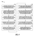
- FIG. 9 is a flow diagram of another method 900 of determining a calibration matrix for a multi-dimensional posture sensor. Similar to the method 600 of FIG. 6 , at block 905 , a first sensor output is measured for a first device axis while the subject is in a first specified posture.
- the first specified posture is the upright posture and the first sensor output can be a u,Upright .
- the first specified posture is the supine posture and the first sensor output can be a w, Supine .
- Other postures e.g., lying on one's side
- a second sensor output is measured for one of a second device axis or a third device axis while the subject is in the first specified posture.
- the first sensor output can be a u,Upright and the second sensor output can be a v,Upright or a w,Upright .
- the first sensor output can be a w, Supine and the second sensor output can be a v, Supine or a u, Supine .
- a sensor output is measured for both the second device axis and the third device axis.
- a third sensor output is measured for the first device axis while the subject is in a second specified posture.
- the second specified posture can be non-orthogonal to the first specified posture.
- the first posture can be the upright posture
- the first sensor output can be a u,Upright
- the second specified posture can be more supine than the first posture and less than fully supine
- the third sensor output may be a u, less than Supine .
- the first specified posture can be the supine posture
- the first sensor output may be a w, Supine
- the second posture can be more upright than the first posture and less than fully upright
- the third sensor output may be a w, less than Upright .
- a fourth sensor output for the second device axis is measured while the subject is in the second specified posture.
- the fourth sensor output may be a v, less than Supine .
- the fourth sensor output may be a v, less than Upright .
- a fifth sensor output for the third device axis measured while the subject is in the second specified posture may be a w, less than supine . In some examples, the fifth sensor output may be a u, less than Upright .
- a first coordinate transformation associated with a first orientation angle is calculated, and at block 935 , a second coordinate transformation associated with a second orientation angle is calculated using the first sensor output and the second sensor output.
- the first and second transformations include the two (right-most) rotations on [a u a v a w ] T in equations (30) or (34).
- transformed third, fourth, and fifth sensor outputs are generated using the first and second coordinate transformations.
- transformed sensor outputs a x ′, a y ′, and a z ′ are generated from sensor outputs a u , a y , a w , using the rotations as in equation (31) or in equation (35).
- elements of the calibration matrix are calculated using the first and second sensor outputs and the transformed sensor outputs.
- the first posture maneuver is upright and the second maneuver is less than fully supine and the elements of the calibration matrix are calculated using s p , c p , s r , and c r using equations (26), and using s y , c y using the equations (32).
- the first posture maneuver is supine and the second maneuver is less than fully upright and the elements of the calibration matrix are calculated using s p , c p , s r , and c r using equations (27), and using s y , c y using the equations (36).
- the calibration matrix can be used to determine subsequent subject posture from subsequent sensor output.
- FIG. 10 is a block diagram of an example of portions of a device 1000 capable of determining a calibration matrix for a multi-dimensional posture sensor.
- the device can be an implantable medical device, and in some examples the device 1000 can be a wearable medical device.
- the multi-dimensional posture sensor 1005 provides an electrical sensor output representative of alignment of respective first, second, and third non-parallel axes of the device 1000 with the gravitational field of the earth.
- the posture sensor 1005 provides an output for each of the first, second, and third non-parallel axes of the device 1000 .
- the device 1000 includes a processor 1010 , such as a microprocessor, digital signal processor (DSP), or other kind of processor.
- the processor 1010 can be an application specific integrated circuit (ASIC).
- ASIC application specific integrated circuit
- the processor 1010 can be communicatively coupled to the posture sensor 1005 .
- the communicative coupling allows the processor 1010 to transmit and/or receive signals to or from the posture sensor 1005 even though there may be intervening circuitry.
- the processor 1010 includes circuits to perform the functions described herein.
- the circuits can be hardware, firmware, or software, or any combination of hardware, firmware, and software.
- the processor 1010 performs instructions embodied in software, firmware, or hardware.
- the processor 1010 includes a sequencer that proceeds through logic functions implemented by hardware. One or more functions may be performed by one circuit.
- the processor 1010 includes a calibration circuit 1015 and a posture circuit 1020 .
- the calibration circuit 1015 and the posture circuit 1020 are configured to perform any of the methods described in regard to FIG. 6 .
- the calibration circuit 1015 measures a first sensor output for the first device axis while the subject is in a first specified posture, measures a second sensor output for one of the second device axis or the third device axis while the subject is in the first specified posture, and measures a third sensor output for the first device axis while the subject is in a second specified posture.
- the first posture can be an upright posture and the second posture can be the supine posture.
- the first device axis can be the “u” device axis of FIG. 4 and the second and third device axes can be the “v” and “w” device axes.
- the first posture is the supine posture and the second posture is an upright posture.
- the first device axis can be the “w” device axis of FIG. 4 and the second and third device axes can be the “u” and “v” device axes.
- the calibration circuit 1015 calculates the posture sensor 1005 by calculating a calibration transformation using the first and second sensor outputs and transformed sensor outputs. In some examples, the calibration circuit 1015 calculates elements of a matrix used to calibrate the posture sensor 1005 using the first, second, and third sensor outputs. As shown above in regards to equations (26) and (27) the calibration circuit 1015 is able to calculate the elements without determining an orientation angle of the device and without using trigonometric functions. After calibration, the posture circuit 1020 determines a subsequent posture of the subject using the posture sensor 1005 .
- the calibration circuit 1015 and the posture circuit 1020 are configured to perform any of the methods described in regard to FIG. 9 .
- the calibration circuit 1015 measures a first sensor output for the first device axis while the subject is in a first specified posture, measure a second sensor output for one of the second device axis or the third device axis while the subject is in the first specified posture, and measure a third sensor output for the first device axis while the subject is in a second specified posture.
- the two specified postures can be non-orthogonal.
- the first posture can be an upright posture and the second posture can be a posture more supine than the upright posture but less than fully supine.
- the first posture can be the supine posture and the second posture can be a posture more upright than the supine posture but less than fully upright.
- the calibration circuit measures a fourth sensor output for the second device axis while the subject is in the second specified posture and measures a fifth sensor output for the third device axis while the subject is in the second specified posture.
- the calibration circuit 1015 then performs coordinate transformations to generate transformed sensor outputs for the second specified posture.
- the calibration circuit 1015 calculates a first coordinate transformation associated with a first orientation angle using a first sensor output, and calculates a second coordinate transformation associated with a second orientation angle using the first sensor output and a second sensor output.
- the transformations are performed using first and second rotation matrices.
- the transformed sensor outputs are generated by multiplying the third, fourth, and fifth sensor outputs by the first and second rotation matrices. Examples are described above in regard to equations (31) and (35).
- the calibration circuit 1015 calculates elements of the first rotation matrix using the first sensor output and calculates elements of the second rotation matrix using the first sensor output and the second sensor output.
- the calibration circuit 1015 calculates the elements of the calibration matrix using the first and second sensor outputs and using the transformed sensor outputs.
- the calibration circuit calculates the matrix elements using matrix components (or coefficients) s p , c p , s r , c r , s y , and c y .
- the first set of matrix components, s p and c p is associated a first orientation angle (e.g., ⁇ p , or ⁇ p′ ) and is calculated using the first sensor output, such as by equations (26) or equations (27).
- the second set of matrix components can be either s r and c r , or s y and c y , associated with a second orientation angle (e.g., ⁇ r or ⁇ y′ respectively).
- the second set of matrix components is calculated using the first sensor output and the second sensor output, such as by equations (26) or (27). Note that the equations indicate that there is a choice over which sensor measurement to use as the second sensor output. Theoretically, either choice should produce identical results, but in practice one choice can be more desirable due to inaccuracies in the patient maneuver or noise in the measurements during the maneuver.
- the third set of matrix components can be either s y and c y , or s r and c r , associated with a second orientation angle (e.g., ⁇ y or ⁇ r ′ respectively).
- the third set of components is calculated using the transformed sensor outputs, such as by equations (32) or (36).
- the first, second, and third sets of matrix components s p , c p , s r , c r , s y , and c y are then used to calculate the matrix elements of the calibration matrix M, such as the matrix elements in equations (9) and (11), or equations (22) and (24).
- the matrix components, and therefore the matrix elements are calculated using the resulting algebraic equations, and are calculated without a determination of any of the orientation angles of the device 1000 or using trigonometric functions. This can reduce the amount of processing power required by the processor 1010 .
- the posture circuit 1020 receives a sensor output (e.g., a DC-responsive voltage level) for each of the three non-parallel axes of the posture sensor 1005 and compares the sensor outputs to specified sensor output thresholds to determine posture of the subject.
- the calibration circuit 1015 adjusts the specified sensor output thresholds using the calculated elements of the calibration matrix.
- the posture circuit 1020 determines subject posture by calculating
- M ⁇ 1 is the inverse of the calibration matrix determined by the calibration circuit
- a u , a v , a w are the sensor outputs for each of three orthogonal axes of the multi-dimensional sensor
- a x , a y , a z are the corresponding measurements or values in the body coordinate system.
- the posture circuit 1020 compares the body coordinate measurements to specified thresholds to determine the posture of the subject.
- the processor 1010 includes a trend circuit 1025 that trends a posture of the subject.
- the device 1000 provides an indication of progression of heart disease of the subject at least in part according to the trend. For example, a patient may, due to progression of heart disease, assume a more upright resting position over time.
- the processor 1010 can initiate sending an indication (e.g., an alert or alarm) to a user or process (e.g., a process executing in an external programmer or at a remote system) of the progression of the disease.
- the device 1000 includes a respiration sensor 1030 communicatively coupled to the processor 1010 .
- a respiration sensor is a transthoracic impedance sensor used to measure minute respiration volume or tidal volume.
- An approach to measuring transthoracic impedance is described in Hartley et al.,U.S. Pat. No. 6,076,015 “Rate Adaptive Cardiac Rhythm Management Device Using Transthoracic Impedance,” filed Feb. 27, 1998, which is incorporated herein by reference in its entirety.
- the respiration sensor provides a signal representative of respiration of the subject.
- the processor 1010 calculates tidal volume of the subject using the respiration signal.
- the trend circuit 1025 trends the tidal volume of the subject according to a determined posture of the subject.
- the device 1000 includes an arterial pressure sensor 1035 communicatively coupled to the processor 1010 .
- An example of an arterial pressure sensor includes a pulmonary arterial (PA) pressure sensor.
- PA pressure includes the pressure within a pulmonary artery due to blood leaving the right ventricle through the pulmonary valve and going to the lungs.
- the arterial pressure sensor provides a signal representative of PA pressure of the subject.
- the trend circuit 1025 trends PA pressure of the subject according to a determined posture of the subject.
- the processor 1010 detects episodes of low blood pressure or high blood pressure using the pressure signal.
- the trend circuit 1025 trends episodes of low or high blood pressure according to a determined posture of the subject.
- Posture sensing in an implantable or a wearable medical device allows improved monitoring of heart failure patients.
- Proper calibration of the posture sensor removes variation of the orientation of the sensor due to patient anatomy and due to device migration.
- the terms “a” or “an” are used, as is common in patent documents, to include one or more than one, independent of any other instances or usages of “at least one” or “one or more.”
- the term “or” is used to refer to a nonexclusive or, such that “A or B” includes “A but not B,” “B but not A,” and “A and B,” unless otherwise indicated.
- Method examples described herein can be machine or computer-implemented at least in part. Some examples can include a computer-readable medium or machine-readable medium encoded with instructions operable to configure an electronic device to perform methods as described in the above examples.
- An implementation of such methods can include code, such as microcode, assembly language code, a higher-level language code, or the like. Such code can include computer readable instructions for performing various methods. The code can form portions of computer program products. Further, the code can be tangibly stored on one or more volatile or non-volatile computer-readable media during execution or at other times.
- These computer-readable media can include, but are not limited to, hard disks, removable magnetic disks, removable optical disks (e.g., compact disks and digital video disks), magnetic cassettes, memory cards or sticks, random access memories (RAM's), read only memories (ROM's), and the like.
Landscapes
- Health & Medical Sciences (AREA)
- Life Sciences & Earth Sciences (AREA)
- Heart & Thoracic Surgery (AREA)
- Physiology (AREA)
- Veterinary Medicine (AREA)
- Public Health (AREA)
- Physics & Mathematics (AREA)
- Biophysics (AREA)
- General Health & Medical Sciences (AREA)
- Engineering & Computer Science (AREA)
- Biomedical Technology (AREA)
- Animal Behavior & Ethology (AREA)
- Molecular Biology (AREA)
- Surgery (AREA)
- Medical Informatics (AREA)
- Pathology (AREA)
- Oral & Maxillofacial Surgery (AREA)
- Dentistry (AREA)
- Cardiology (AREA)
- Hematology (AREA)
- Nuclear Medicine, Radiotherapy & Molecular Imaging (AREA)
- Radiology & Medical Imaging (AREA)
- General Physics & Mathematics (AREA)
- Measurement Of The Respiration, Hearing Ability, Form, And Blood Characteristics Of Living Organisms (AREA)
- Electrotherapy Devices (AREA)
Abstract
Description
where a′ represents the vector expressed in the coordinate system rotated through angle θy about the z axis.
where a″ represents the vector expressed in the coordinate system rotated through angle θy about the z axis and then rotated through θp about the y′ axis.
where a′″ represents the vector expressed in the coordinate system rotated through angle θy about the z axis, rotated through θp about the y′ axis, and then rotated through angle θr, about the x″ axis. The matrix on the right side of the equal sign can be multiplied out to yield:
where aT=[au av aw]T is the vector a expressed in the rotated coordinate system of the device.
then by inspection, m13=au,Upright., m23=av,Upright., m33=aw,Upright., where au,Upright refers to the sensor output from the “u” device axis when the patient is in the upright position.
Pitch Angle (P) Coefficients
where, e.g., cos(θp) is equal to cp. It can be seen that the nine components of the matrix are composed of the six coefficients sr, cr, sp, cp, and sy, cy. The “s” and “c” coefficients or matrix components are also related to one another as discussed previously.
s p =a u,Upright
c p=±√{square root over (1−s p 2)}
s ra =a v,Upright /c p , c ra=±√{square root over (1−s ra 2)},
c rb =a w,Upright /c p , s rb=±√{square root over (1−c rb 2)}, (10)
where the additional “a” and “b” in the subscripts denote that these are two alternative sets of calculations that, as noted previously, may give different results in practice. Either the set “a” or the set “b” equations can be used. Note that sr, cr should be calculated from the same set of equations so that sr and cr are calculated from complementary angles. This ensures that the rotation matrix is unitary (i.e., its inverse is equal to its transpose). Thus, by knowing au,Upright and av,Upright, or knowing au,Upright and aw,Upright, four of the six coefficients can be calculated.
Yaw Angle (Y) Coefficients
where [au av aw] is the output of the posture sensor in device coordinates and [ax ay az] is the output of the posture sensor in body coordinates.
Alternate Coordinate Transformation
where a′ represents the vector expressed in the coordinate system rotated through angle θr′ about the x axis.
where a″ represents the vector expressed in the coordinate system rotated through angle θr′ about the x axis and then rotated through θp′, about the y′ axis.
where a′″=[ax′″ ay′″ az′″] represents the vector expressed in the coordinate system rotated through angle θ′r′, about the x axis, rotated through θp′, about the y′ axis, and then rotated through angle θy′ about the z″ axis. The matrix on the right side of the equal sign can be multiplied out to yield:
where aT=[au av aw]T is the vector a expressed in the device coordinates.
and by inspection m11=au, Supine., m21=av, Supine, m31=aw, Supine, where au, Supine. refers to the sensor output from the “u” device axis when the patient is in the supine position.
P′ Angle Coefficients
In simplified notation, the non-trigonometric equations are:
s p =−a w,Supine
c P=±√{square root over (1−s p 2)},
s ya =a v,Supine /c p , c ya=±√{square root over (1−s ya 2)},
c yb =a u,Supine /c p , s yb=±√{square root over (1−c yb 2)}, (23)
where the additional “a” and “b” in the subscripts denote that these are two alternative sets of calculations may give different results in practice. Either the set “a” or the set “b” equations should be used and sy, cy calculated from the same set of equations. Thus, by knowing aw, Supine and av, Supine, or knowing aw, Supine and au, Supine, four of the six coefficients can be calculated.
R′ Angle Coefficients
The simplest set of calculations for the θr′ coefficients is cr=aw,Upright/cp,sr=±√{square root over (1−cr 2)}. All six of the coefficients can be calculated and therefore all nine elements of the calibration matrix M can be calculated. As with the first example where the subject is first upright and is supine second, the elements of the calibration matrix are calculated without using a trigonometric function and without expressly calculating an orientation angle.
s p =a ,Upright
c p=±√{square root over (1−s p 2)}
s ra =a v,Upright /c p , c ra=±√{square root over (1−s ra 2)},
c rb =a w,Upright /c p , s rb=±√{square root over (1−c rb 2)},
c y =a u,Supine /c p,
s y=±√{square root over (1−c y 2)}, (26)
without expressly calculating any of the orientation angles θp, θr, or θy. The first set of matrix components sp, cp, is related to a first orientation angle θp, and are calculated using the first sensor output au,Upright. The second set of matrix components sr, cr, is related to a second orientation angle θr, and are calculated using the first sensor output au,Upright (from sp, cp), and a second sensor output; either av,Upright or aw,Upright. The third set of matrix components sy, cy, is related to a third orientation angle θy, and is calculated using a third sensor output au, Supine. The matrix components sp, cp, sr, cr, sy, and cy are then used to calculate the matrix elements of the calibration matrix M.
s p =−a w,Supine
c p=±√{square root over (1−s p 2)}
s ya =a v,Supine /c p , c ya=±√{square root over (1−s ya 2)},
c yb =a u,Supine /c p ,s yb=±√{square root over (1−c yb 2)},
c r =a w,Upright /c p,
s r=±√{square root over (1−c r 2)}, (27)
without expressly calculating any of the orientation angles θp′, θr′, or θy′.
where ax, ay, az are the corresponding sensor measurements, or g vector, in the body coordinate system. The converted or transformed sensor outputs ax, ay, az are compared to specified thresholds (e.g., programmed into a medical device) to determine posture.
r=√{square root over (a x ′2 +a ′2)},
c y =a x′ /r
s y =a y′ /r. (32)
r=√{square root over (a y ′2 +a z ′2)},
s r =a y′ /r,
c r =a z′ /r (36)
where M−1 is the inverse of the calibration matrix determined by the calibration circuit, au, av, aw, are the sensor outputs for each of three orthogonal axes of the multi-dimensional sensor, and ax, ay, az, are the corresponding measurements or values in the body coordinate system. The
Claims (20)
Priority Applications (1)
| Application Number | Priority Date | Filing Date | Title |
|---|---|---|---|
| US13/024,823 US10328267B2 (en) | 2010-02-15 | 2011-02-10 | Methods for constructing posture calibration matrices |
Applications Claiming Priority (2)
| Application Number | Priority Date | Filing Date | Title |
|---|---|---|---|
| US30464910P | 2010-02-15 | 2010-02-15 | |
| US13/024,823 US10328267B2 (en) | 2010-02-15 | 2011-02-10 | Methods for constructing posture calibration matrices |
Publications (2)
| Publication Number | Publication Date |
|---|---|
| US20110201969A1 US20110201969A1 (en) | 2011-08-18 |
| US10328267B2 true US10328267B2 (en) | 2019-06-25 |
Family
ID=43921080
Family Applications (1)
| Application Number | Title | Priority Date | Filing Date |
|---|---|---|---|
| US13/024,823 Active 2035-12-02 US10328267B2 (en) | 2010-02-15 | 2011-02-10 | Methods for constructing posture calibration matrices |
Country Status (5)
| Country | Link |
|---|---|
| US (1) | US10328267B2 (en) |
| EP (1) | EP2536334B1 (en) |
| JP (1) | JP5650765B2 (en) |
| AU (1) | AU2011215822B2 (en) |
| WO (1) | WO2011100422A1 (en) |
Cited By (5)
| Publication number | Priority date | Publication date | Assignee | Title |
|---|---|---|---|---|
| US11738197B2 (en) | 2019-07-25 | 2023-08-29 | Inspire Medical Systems, Inc. | Systems and methods for operating an implantable medical device based upon sensed posture information |
| US11890101B2 (en) | 2019-08-02 | 2024-02-06 | Cardiac Pacemakers, Inc. | Calibration of implantable device orientation |
| WO2025024195A1 (en) | 2023-07-21 | 2025-01-30 | Cardiac Pacemakers, Inc. | Method for monitoring for trepopnea |
| US12262988B2 (en) | 2019-07-25 | 2025-04-01 | Inspire Medical Systems, Inc. | Respiration detection |
| US12539418B2 (en) | 2016-04-19 | 2026-02-03 | Inspire Medical Systems, Inc. | Accelerometer-based sensing for sleep disordered breathing (SDB) care |
Families Citing this family (18)
| Publication number | Priority date | Publication date | Assignee | Title |
|---|---|---|---|---|
| AU2011215822B2 (en) | 2010-02-15 | 2013-05-23 | Cardiac Pacemakers, Inc. | Methods for constructing posture calibration matrices |
| US20130165819A1 (en) * | 2011-12-23 | 2013-06-27 | Pacesetter, Inc. | System and method for controlling radio frequency scanning attributes of an implantable medical device |
| CN103186687A (en) * | 2011-12-30 | 2013-07-03 | 百度在线网络技术(北京)有限公司 | Simulator gravity sensing data acquisition method and device |
| CN103186257B (en) * | 2011-12-30 | 2016-03-23 | 百度在线网络技术(北京)有限公司 | A kind of simulator rotating vector sensed data acquisition methods and device |
| CN103186688A (en) * | 2011-12-30 | 2013-07-03 | 百度在线网络技术(北京)有限公司 | Simulator magnetic sensing data acquisition method and device |
| US9907959B2 (en) | 2012-04-12 | 2018-03-06 | Medtronic, Inc. | Velocity detection for posture-responsive therapy |
| US10719574B2 (en) * | 2012-07-12 | 2020-07-21 | Vital Connect, Inc. | Calibration of a chest-mounted wireless sensor device for posture and activity detection |
| US9035794B2 (en) | 2012-07-12 | 2015-05-19 | Vital Connect, Inc. | Posture calibration for activity monitoring |
| US9632981B2 (en) | 2012-07-12 | 2017-04-25 | Vital Connect, Inc. | Calibration of a chest-mounted wireless sensor device for posture and activity detection |
| US10373714B1 (en) | 2013-07-12 | 2019-08-06 | Vital Connect, Inc. | Determination of bed-time duration using wearable sensors |
| US9585602B1 (en) * | 2013-10-07 | 2017-03-07 | Intellirod Spine Inc. | Obtaining medical diagnostic measurements |
| WO2015153837A1 (en) | 2014-04-04 | 2015-10-08 | Med-El Elektromedizinische Geraete Gmbh | Acceleration sensors for recording of triggered respiratory signals in neurostmulators |
| US11033201B2 (en) | 2015-09-04 | 2021-06-15 | Biosense Webster (Israel) Ltd. | Inconsistent field-based patch location coordinate correction |
| WO2017163521A1 (en) * | 2016-03-23 | 2017-09-28 | 日本電気株式会社 | Information processing device, control method for information processing device, and control program for information processing device |
| BR112018071163A8 (en) * | 2016-04-13 | 2023-03-14 | Strong Arm Tech Inc | SYSTEMS AND DEVICES FOR MOTION TRACKING, EVALUATION AND MONITORING AND THEIR METHODS OF USE |
| US12004852B2 (en) * | 2017-09-28 | 2024-06-11 | Vital Connect, Inc. | Sensor calibration considering subject-dependent variables and/or body positions |
| US11116989B2 (en) | 2019-05-29 | 2021-09-14 | Pacesetter, Inc. | Implantable medical device for arrhythmia detection |
| US11596342B2 (en) | 2019-09-19 | 2023-03-07 | Medtronic, Inc. | Automatic detection of body planes of rotation |
Citations (15)
| Publication number | Priority date | Publication date | Assignee | Title |
|---|---|---|---|---|
| US5593431A (en) | 1995-03-30 | 1997-01-14 | Medtronic, Inc. | Medical service employing multiple DC accelerometers for patient activity and posture sensing and method |
| US6044297A (en) | 1998-09-25 | 2000-03-28 | Medtronic, Inc. | Posture and device orientation and calibration for implantable medical devices |
| US6076015A (en) | 1998-02-27 | 2000-06-13 | Cardiac Pacemakers, Inc. | Rate adaptive cardiac rhythm management device using transthoracic impedance |
| US7149579B1 (en) | 2002-12-23 | 2006-12-12 | Pacesetter, Inc. | System and method for determining patient posture based on 3-D trajectory using an implantable medical device |
| US7149584B1 (en) | 2002-12-23 | 2006-12-12 | Pacesetter, Inc. | System and method for determining patient posture based on 3-D trajectory using an implantable medical device |
| US20070032748A1 (en) * | 2005-07-28 | 2007-02-08 | 608442 Bc Ltd. | System for detecting and analyzing body motion |
| US20070118056A1 (en) | 2005-11-18 | 2007-05-24 | Hua Wang | Posture detector calibration and use |
| US20070115277A1 (en) | 2005-11-18 | 2007-05-24 | Hua Wang | Posture detection system |
| US20080091373A1 (en) * | 2006-07-31 | 2008-04-17 | University Of New Brunswick | Method for calibrating sensor positions in a human movement measurement and analysis system |
| US20080288200A1 (en) | 2007-05-18 | 2008-11-20 | Noble Christopher R | Newtonian physical activity monitor |
| JP2009276094A (en) | 2008-05-12 | 2009-11-26 | Sumitomo Electric Ind Ltd | Attitude determination apparatus and method, movement direction determination apparatus, position determination apparatus, and computer program |
| US20090312973A1 (en) * | 2008-06-12 | 2009-12-17 | Hatlestad John D | Posture sensor automatic calibration |
| WO2011100422A1 (en) | 2010-02-15 | 2011-08-18 | Cardiac Pacemakers, Inc. | Methods for constructing posture calibration matrices |
| US20110313327A1 (en) * | 2009-01-16 | 2011-12-22 | Koninklijke Philips Electronics N.V. | Method for automatic alignment of a position and orientation indicator and device for monitoring the movements of a body part |
| US8708934B2 (en) * | 2008-07-11 | 2014-04-29 | Medtronic, Inc. | Reorientation of patient posture states for posture-responsive therapy |
-
2011
- 2011-02-10 AU AU2011215822A patent/AU2011215822B2/en not_active Ceased
- 2011-02-10 EP EP11704159.0A patent/EP2536334B1/en active Active
- 2011-02-10 JP JP2012552995A patent/JP5650765B2/en not_active Expired - Fee Related
- 2011-02-10 WO PCT/US2011/024339 patent/WO2011100422A1/en not_active Ceased
- 2011-02-10 US US13/024,823 patent/US10328267B2/en active Active
Patent Citations (20)
| Publication number | Priority date | Publication date | Assignee | Title |
|---|---|---|---|---|
| US5593431A (en) | 1995-03-30 | 1997-01-14 | Medtronic, Inc. | Medical service employing multiple DC accelerometers for patient activity and posture sensing and method |
| US6076015A (en) | 1998-02-27 | 2000-06-13 | Cardiac Pacemakers, Inc. | Rate adaptive cardiac rhythm management device using transthoracic impedance |
| US6044297A (en) | 1998-09-25 | 2000-03-28 | Medtronic, Inc. | Posture and device orientation and calibration for implantable medical devices |
| WO2000018317A2 (en) | 1998-09-25 | 2000-04-06 | Medtronic, Inc. | Posture and device orientation sensing and calibration for implantable medical devices |
| US7149579B1 (en) | 2002-12-23 | 2006-12-12 | Pacesetter, Inc. | System and method for determining patient posture based on 3-D trajectory using an implantable medical device |
| US7149584B1 (en) | 2002-12-23 | 2006-12-12 | Pacesetter, Inc. | System and method for determining patient posture based on 3-D trajectory using an implantable medical device |
| US20070032748A1 (en) * | 2005-07-28 | 2007-02-08 | 608442 Bc Ltd. | System for detecting and analyzing body motion |
| JP2009515662A (en) | 2005-11-18 | 2009-04-16 | カーディアック ペースメイカーズ, インコーポレイテッド | Calibration and use of posture detector |
| US20070118056A1 (en) | 2005-11-18 | 2007-05-24 | Hua Wang | Posture detector calibration and use |
| US20070115277A1 (en) | 2005-11-18 | 2007-05-24 | Hua Wang | Posture detection system |
| WO2007061746A2 (en) | 2005-11-18 | 2007-05-31 | Cardiac Pacemakers, Inc. | Posture detector calibration and use |
| US20080091373A1 (en) * | 2006-07-31 | 2008-04-17 | University Of New Brunswick | Method for calibrating sensor positions in a human movement measurement and analysis system |
| US20080288200A1 (en) | 2007-05-18 | 2008-11-20 | Noble Christopher R | Newtonian physical activity monitor |
| JP2009276094A (en) | 2008-05-12 | 2009-11-26 | Sumitomo Electric Ind Ltd | Attitude determination apparatus and method, movement direction determination apparatus, position determination apparatus, and computer program |
| US20090312973A1 (en) * | 2008-06-12 | 2009-12-17 | Hatlestad John D | Posture sensor automatic calibration |
| US8708934B2 (en) * | 2008-07-11 | 2014-04-29 | Medtronic, Inc. | Reorientation of patient posture states for posture-responsive therapy |
| US20110313327A1 (en) * | 2009-01-16 | 2011-12-22 | Koninklijke Philips Electronics N.V. | Method for automatic alignment of a position and orientation indicator and device for monitoring the movements of a body part |
| WO2011100422A1 (en) | 2010-02-15 | 2011-08-18 | Cardiac Pacemakers, Inc. | Methods for constructing posture calibration matrices |
| AU2011215822B2 (en) | 2010-02-15 | 2013-05-23 | Cardiac Pacemakers, Inc. | Methods for constructing posture calibration matrices |
| EP2536334B1 (en) | 2010-02-15 | 2013-12-25 | Cardiac Pacemakers, Inc. | Methods for constructing posture calibration matrices |
Non-Patent Citations (7)
| Title |
|---|
| "Australian Application Serial No. 2011215822, First Examiner Report dated Feb. 5, 2013", 3 pgs. |
| "International Application Serial No. PCT/US2011/024339, International Search Report dated May 24, 2011", 4 pgs. |
| "International Application Serial No. PCT/US2011/024339, Written Opinion dated May 24, 2011", 7 pgs. |
| "Japanese Application Serial No. 2012-552995, Office Action dated Dec. 24, 2013", With English Translation, 8 pgs. |
| "Japanese Application Serial No. 2012-552995, Office Action dated Sep. 2, 2014", With English Translation, 5 pgs. |
| Brown, G., "An Accelerometer Based Fall Detector : Development, Experimentation, and Analysis", [online]. 1985, EECS/SUPERB [retrieved Feb. 13, 2008]. Retrieved from the Internet: <URL: http://bsn.citris.berkeley.edu/media/GarrettFinalPaper.pdf>, (Jul. 2005), 9 pgs. |
| International Application Serial No. PCT/US2011/024339, International Preliminary Report on Patentability dated Aug. 30, 2012, 7 pgs. |
Cited By (5)
| Publication number | Priority date | Publication date | Assignee | Title |
|---|---|---|---|---|
| US12539418B2 (en) | 2016-04-19 | 2026-02-03 | Inspire Medical Systems, Inc. | Accelerometer-based sensing for sleep disordered breathing (SDB) care |
| US11738197B2 (en) | 2019-07-25 | 2023-08-29 | Inspire Medical Systems, Inc. | Systems and methods for operating an implantable medical device based upon sensed posture information |
| US12262988B2 (en) | 2019-07-25 | 2025-04-01 | Inspire Medical Systems, Inc. | Respiration detection |
| US11890101B2 (en) | 2019-08-02 | 2024-02-06 | Cardiac Pacemakers, Inc. | Calibration of implantable device orientation |
| WO2025024195A1 (en) | 2023-07-21 | 2025-01-30 | Cardiac Pacemakers, Inc. | Method for monitoring for trepopnea |
Also Published As
| Publication number | Publication date |
|---|---|
| JP5650765B2 (en) | 2015-01-07 |
| EP2536334A1 (en) | 2012-12-26 |
| WO2011100422A1 (en) | 2011-08-18 |
| AU2011215822A1 (en) | 2012-09-20 |
| JP2013519444A (en) | 2013-05-30 |
| US20110201969A1 (en) | 2011-08-18 |
| AU2011215822B2 (en) | 2013-05-23 |
| EP2536334B1 (en) | 2013-12-25 |
Similar Documents
| Publication | Publication Date | Title |
|---|---|---|
| US10328267B2 (en) | Methods for constructing posture calibration matrices | |
| EP1855758B1 (en) | Implantable cardiac device with dyspnea measurement | |
| CN101711125B (en) | Long-term implantable active fixed medical electronic leads for non-fluoroscopy implants | |
| US8747314B2 (en) | Cardiovascular pressure annotations and logbook | |
| US7951087B2 (en) | Method for correction of posture dependence on heart sounds | |
| US9968787B2 (en) | Spatial configuration of a motion sensor in an implantable medical device | |
| US11890101B2 (en) | Calibration of implantable device orientation | |
| US20140277237A1 (en) | Device based optimization of device therapies | |
| US10166001B2 (en) | Trending S1 heart sounds amplitudes in ambulatory patients for worsening HF detection | |
| US8858448B2 (en) | Monitoring projections along principal components of multiple sensors as an indicator of worsening heart failure | |
| US20250025097A1 (en) | Method for monitoring trepopnea in heart failure patients | |
| US10945670B2 (en) | Minute volume sensor optimization using quadripolar leads |
Legal Events
| Date | Code | Title | Description |
|---|---|---|---|
| AS | Assignment |
Owner name: CARDIAC PACEMAKERS, INC., MINNESOTA Free format text: ASSIGNMENT OF ASSIGNORS INTEREST;ASSIGNORS:HATLESTAD, JOHN D.;CHAN, TSZ PING;SIGNING DATES FROM 20110308 TO 20110317;REEL/FRAME:026110/0151 |
|
| STPP | Information on status: patent application and granting procedure in general |
Free format text: NOTICE OF ALLOWANCE MAILED -- APPLICATION RECEIVED IN OFFICE OF PUBLICATIONS |
|
| STPP | Information on status: patent application and granting procedure in general |
Free format text: PUBLICATIONS -- ISSUE FEE PAYMENT VERIFIED |
|
| STCF | Information on status: patent grant |
Free format text: PATENTED CASE |
|
| MAFP | Maintenance fee payment |
Free format text: PAYMENT OF MAINTENANCE FEE, 4TH YEAR, LARGE ENTITY (ORIGINAL EVENT CODE: M1551); ENTITY STATUS OF PATENT OWNER: LARGE ENTITY Year of fee payment: 4 |