US10328212B2 - Single slider double barrel syringe and method to use same for medical diagnostics, therapeutic use, and placement confirmation and joint space injection - Google Patents
Single slider double barrel syringe and method to use same for medical diagnostics, therapeutic use, and placement confirmation and joint space injection Download PDFInfo
- Publication number
- US10328212B2 US10328212B2 US15/491,730 US201715491730A US10328212B2 US 10328212 B2 US10328212 B2 US 10328212B2 US 201715491730 A US201715491730 A US 201715491730A US 10328212 B2 US10328212 B2 US 10328212B2
- Authority
- US
- United States
- Prior art keywords
- hub
- slider
- barrel
- barrel lumen
- orifice
- Prior art date
- Legal status (The legal status is an assumption and is not a legal conclusion. Google has not performed a legal analysis and makes no representation as to the accuracy of the status listed.)
- Active, expires
Links
- 238000002347 injection Methods 0.000 title description 65
- 239000007924 injection Substances 0.000 title description 65
- 238000000034 method Methods 0.000 title description 15
- 230000001225 therapeutic effect Effects 0.000 title description 3
- 238000012790 confirmation Methods 0.000 title 1
- 238000012360 testing method Methods 0.000 claims abstract description 62
- 210000001124 body fluid Anatomy 0.000 claims abstract description 35
- 239000012530 fluid Substances 0.000 claims description 176
- 230000008878 coupling Effects 0.000 claims description 24
- 238000010168 coupling process Methods 0.000 claims description 24
- 238000005859 coupling reaction Methods 0.000 claims description 24
- 238000007789 sealing Methods 0.000 claims description 22
- 238000013519 translation Methods 0.000 claims description 10
- 230000007935 neutral effect Effects 0.000 description 13
- 210000003811 finger Anatomy 0.000 description 12
- 239000003814 drug Substances 0.000 description 10
- 230000004044 response Effects 0.000 description 9
- 239000000126 substance Substances 0.000 description 8
- 239000000032 diagnostic agent Substances 0.000 description 6
- 229940039227 diagnostic agent Drugs 0.000 description 6
- 229940124597 therapeutic agent Drugs 0.000 description 6
- 230000008859 change Effects 0.000 description 5
- 238000012864 cross contamination Methods 0.000 description 5
- 239000000463 material Substances 0.000 description 5
- 210000001179 synovial fluid Anatomy 0.000 description 5
- 208000002193 Pain Diseases 0.000 description 4
- 239000003153 chemical reaction reagent Substances 0.000 description 4
- 229920001971 elastomer Polymers 0.000 description 4
- 108090000623 proteins and genes Proteins 0.000 description 4
- 102000004169 proteins and genes Human genes 0.000 description 4
- 210000003813 thumb Anatomy 0.000 description 4
- KIUKXJAPPMFGSW-DNGZLQJQSA-N (2S,3S,4S,5R,6R)-6-[(2S,3R,4R,5S,6R)-3-Acetamido-2-[(2S,3S,4R,5R,6R)-6-[(2R,3R,4R,5S,6R)-3-acetamido-2,5-dihydroxy-6-(hydroxymethyl)oxan-4-yl]oxy-2-carboxy-4,5-dihydroxyoxan-3-yl]oxy-5-hydroxy-6-(hydroxymethyl)oxan-4-yl]oxy-3,4,5-trihydroxyoxane-2-carboxylic acid Chemical compound CC(=O)N[C@H]1[C@H](O)O[C@H](CO)[C@@H](O)[C@@H]1O[C@H]1[C@H](O)[C@@H](O)[C@H](O[C@H]2[C@@H]([C@@H](O[C@H]3[C@@H]([C@@H](O)[C@H](O)[C@H](O3)C(O)=O)O)[C@H](O)[C@@H](CO)O2)NC(C)=O)[C@@H](C(O)=O)O1 KIUKXJAPPMFGSW-DNGZLQJQSA-N 0.000 description 3
- 239000008186 active pharmaceutical agent Substances 0.000 description 3
- 239000003246 corticosteroid Substances 0.000 description 3
- 229920002674 hyaluronan Polymers 0.000 description 3
- 229960003160 hyaluronic acid Drugs 0.000 description 3
- 238000004519 manufacturing process Methods 0.000 description 3
- 239000000853 adhesive Substances 0.000 description 2
- 230000001070 adhesive effect Effects 0.000 description 2
- 238000004891 communication Methods 0.000 description 2
- 238000002059 diagnostic imaging Methods 0.000 description 2
- 239000000975 dye Substances 0.000 description 2
- 239000000806 elastomer Substances 0.000 description 2
- 239000011521 glass Substances 0.000 description 2
- 238000007913 intrathecal administration Methods 0.000 description 2
- 230000007257 malfunction Effects 0.000 description 2
- 239000000546 pharmaceutical excipient Substances 0.000 description 2
- 239000004033 plastic Substances 0.000 description 2
- 229920000642 polymer Polymers 0.000 description 2
- 238000002360 preparation method Methods 0.000 description 2
- 230000002285 radioactive effect Effects 0.000 description 2
- 150000003431 steroids Chemical class 0.000 description 2
- 230000000007 visual effect Effects 0.000 description 2
- 208000000094 Chronic Pain Diseases 0.000 description 1
- WQZGKKKJIJFFOK-GASJEMHNSA-N Glucose Natural products OC[C@H]1OC(O)[C@H](O)[C@@H](O)[C@@H]1O WQZGKKKJIJFFOK-GASJEMHNSA-N 0.000 description 1
- 108010015776 Glucose oxidase Proteins 0.000 description 1
- 239000004366 Glucose oxidase Substances 0.000 description 1
- 102000005548 Hexokinase Human genes 0.000 description 1
- 108700040460 Hexokinases Proteins 0.000 description 1
- 206010061218 Inflammation Diseases 0.000 description 1
- 230000001154 acute effect Effects 0.000 description 1
- 208000005298 acute pain Diseases 0.000 description 1
- 230000000202 analgesic effect Effects 0.000 description 1
- 210000003484 anatomy Anatomy 0.000 description 1
- 230000003110 anti-inflammatory effect Effects 0.000 description 1
- 238000013459 approach Methods 0.000 description 1
- 206010003246 arthritis Diseases 0.000 description 1
- 230000000712 assembly Effects 0.000 description 1
- 238000000429 assembly Methods 0.000 description 1
- 210000000845 cartilage Anatomy 0.000 description 1
- 238000006243 chemical reaction Methods 0.000 description 1
- 230000006835 compression Effects 0.000 description 1
- 238000007906 compression Methods 0.000 description 1
- ARUVKPQLZAKDPS-UHFFFAOYSA-L copper(II) sulfate Chemical compound [Cu+2].[O-][S+2]([O-])([O-])[O-] ARUVKPQLZAKDPS-UHFFFAOYSA-L 0.000 description 1
- 229910000366 copper(II) sulfate Inorganic materials 0.000 description 1
- 230000001934 delay Effects 0.000 description 1
- 230000000881 depressing effect Effects 0.000 description 1
- 230000000994 depressogenic effect Effects 0.000 description 1
- -1 e.g. Substances 0.000 description 1
- 239000008103 glucose Substances 0.000 description 1
- 229940116332 glucose oxidase Drugs 0.000 description 1
- 235000019420 glucose oxidase Nutrition 0.000 description 1
- 230000036541 health Effects 0.000 description 1
- 230000002757 inflammatory effect Effects 0.000 description 1
- 230000004054 inflammatory process Effects 0.000 description 1
- 239000003589 local anesthetic agent Substances 0.000 description 1
- 238000005461 lubrication Methods 0.000 description 1
- 230000007246 mechanism Effects 0.000 description 1
- 230000000116 mitigating effect Effects 0.000 description 1
- 230000000399 orthopedic effect Effects 0.000 description 1
- 201000008482 osteoarthritis Diseases 0.000 description 1
- 230000037361 pathway Effects 0.000 description 1
- 230000003068 static effect Effects 0.000 description 1
- 210000001519 tissue Anatomy 0.000 description 1
- 230000007704 transition Effects 0.000 description 1
- 238000013022 venting Methods 0.000 description 1
- 238000003466 welding Methods 0.000 description 1
Images


Classifications
-
- A—HUMAN NECESSITIES
- A61—MEDICAL OR VETERINARY SCIENCE; HYGIENE
- A61M—DEVICES FOR INTRODUCING MEDIA INTO, OR ONTO, THE BODY; DEVICES FOR TRANSDUCING BODY MEDIA OR FOR TAKING MEDIA FROM THE BODY; DEVICES FOR PRODUCING OR ENDING SLEEP OR STUPOR
- A61M5/00—Devices for bringing media into the body in a subcutaneous, intra-vascular or intramuscular way; Accessories therefor, e.g. filling or cleaning devices, arm-rests
- A61M5/178—Syringes
- A61M5/31—Details
- A61M5/315—Pistons; Piston-rods; Guiding, blocking or restricting the movement of the rod or piston; Appliances on the rod for facilitating dosing ; Dosing mechanisms
- A61M5/31565—Administration mechanisms, i.e. constructional features, modes of administering a dose
- A61M5/31576—Constructional features or modes of drive mechanisms for piston rods
-
- A—HUMAN NECESSITIES
- A61—MEDICAL OR VETERINARY SCIENCE; HYGIENE
- A61M—DEVICES FOR INTRODUCING MEDIA INTO, OR ONTO, THE BODY; DEVICES FOR TRANSDUCING BODY MEDIA OR FOR TAKING MEDIA FROM THE BODY; DEVICES FOR PRODUCING OR ENDING SLEEP OR STUPOR
- A61M39/00—Tubes, tube connectors, tube couplings, valves, access sites or the like, specially adapted for medical use
- A61M39/22—Valves or arrangement of valves
- A61M39/223—Multiway valves
-
- A—HUMAN NECESSITIES
- A61—MEDICAL OR VETERINARY SCIENCE; HYGIENE
- A61M—DEVICES FOR INTRODUCING MEDIA INTO, OR ONTO, THE BODY; DEVICES FOR TRANSDUCING BODY MEDIA OR FOR TAKING MEDIA FROM THE BODY; DEVICES FOR PRODUCING OR ENDING SLEEP OR STUPOR
- A61M5/00—Devices for bringing media into the body in a subcutaneous, intra-vascular or intramuscular way; Accessories therefor, e.g. filling or cleaning devices, arm-rests
- A61M5/178—Syringes
- A61M5/19—Syringes having more than one chamber, e.g. including a manifold coupling two parallelly aligned syringes through separate channels to a common discharge assembly
-
- A—HUMAN NECESSITIES
- A61—MEDICAL OR VETERINARY SCIENCE; HYGIENE
- A61M—DEVICES FOR INTRODUCING MEDIA INTO, OR ONTO, THE BODY; DEVICES FOR TRANSDUCING BODY MEDIA OR FOR TAKING MEDIA FROM THE BODY; DEVICES FOR PRODUCING OR ENDING SLEEP OR STUPOR
- A61M5/00—Devices for bringing media into the body in a subcutaneous, intra-vascular or intramuscular way; Accessories therefor, e.g. filling or cleaning devices, arm-rests
- A61M5/178—Syringes
- A61M5/31—Details
- A61M5/3129—Syringe barrels
-
- A—HUMAN NECESSITIES
- A61—MEDICAL OR VETERINARY SCIENCE; HYGIENE
- A61M—DEVICES FOR INTRODUCING MEDIA INTO, OR ONTO, THE BODY; DEVICES FOR TRANSDUCING BODY MEDIA OR FOR TAKING MEDIA FROM THE BODY; DEVICES FOR PRODUCING OR ENDING SLEEP OR STUPOR
- A61M5/00—Devices for bringing media into the body in a subcutaneous, intra-vascular or intramuscular way; Accessories therefor, e.g. filling or cleaning devices, arm-rests
- A61M5/178—Syringes
- A61M5/31—Details
- A61M5/315—Pistons; Piston-rods; Guiding, blocking or restricting the movement of the rod or piston; Appliances on the rod for facilitating dosing ; Dosing mechanisms
- A61M5/31511—Piston or piston-rod constructions, e.g. connection of piston with piston-rod
-
- A—HUMAN NECESSITIES
- A61—MEDICAL OR VETERINARY SCIENCE; HYGIENE
- A61B—DIAGNOSIS; SURGERY; IDENTIFICATION
- A61B10/00—Instruments for taking body samples for diagnostic purposes; Other methods or instruments for diagnosis, e.g. for vaccination diagnosis, sex determination or ovulation-period determination; Throat striking implements
- A61B10/0045—Devices for taking samples of body liquids
-
- A—HUMAN NECESSITIES
- A61—MEDICAL OR VETERINARY SCIENCE; HYGIENE
- A61M—DEVICES FOR INTRODUCING MEDIA INTO, OR ONTO, THE BODY; DEVICES FOR TRANSDUCING BODY MEDIA OR FOR TAKING MEDIA FROM THE BODY; DEVICES FOR PRODUCING OR ENDING SLEEP OR STUPOR
- A61M5/00—Devices for bringing media into the body in a subcutaneous, intra-vascular or intramuscular way; Accessories therefor, e.g. filling or cleaning devices, arm-rests
- A61M5/178—Syringes
- A61M5/24—Ampoule syringes, i.e. syringes with needle for use in combination with replaceable ampoules or carpules, e.g. automatic
- A61M2005/2403—Ampoule inserted into the ampoule holder
- A61M2005/2407—Ampoule inserted into the ampoule holder from the rear
-
- A—HUMAN NECESSITIES
- A61—MEDICAL OR VETERINARY SCIENCE; HYGIENE
- A61M—DEVICES FOR INTRODUCING MEDIA INTO, OR ONTO, THE BODY; DEVICES FOR TRANSDUCING BODY MEDIA OR FOR TAKING MEDIA FROM THE BODY; DEVICES FOR PRODUCING OR ENDING SLEEP OR STUPOR
- A61M5/00—Devices for bringing media into the body in a subcutaneous, intra-vascular or intramuscular way; Accessories therefor, e.g. filling or cleaning devices, arm-rests
- A61M5/178—Syringes
- A61M5/31—Details
- A61M2005/3103—Leak prevention means for distal end of syringes, i.e. syringe end for mounting a needle
- A61M2005/3104—Caps for syringes without needle
-
- A—HUMAN NECESSITIES
- A61—MEDICAL OR VETERINARY SCIENCE; HYGIENE
- A61M—DEVICES FOR INTRODUCING MEDIA INTO, OR ONTO, THE BODY; DEVICES FOR TRANSDUCING BODY MEDIA OR FOR TAKING MEDIA FROM THE BODY; DEVICES FOR PRODUCING OR ENDING SLEEP OR STUPOR
- A61M5/00—Devices for bringing media into the body in a subcutaneous, intra-vascular or intramuscular way; Accessories therefor, e.g. filling or cleaning devices, arm-rests
- A61M5/178—Syringes
- A61M5/31—Details
- A61M2005/3117—Means preventing contamination of the medicament compartment of a syringe
- A61M2005/3118—Means preventing contamination of the medicament compartment of a syringe via the distal end of a syringe, i.e. syringe end for mounting a needle cannula
- A61M2005/312—Means preventing contamination of the medicament compartment of a syringe via the distal end of a syringe, i.e. syringe end for mounting a needle cannula comprising sealing means, e.g. severable caps, to be removed prior to injection by, e.g. tearing or twisting
-
- A—HUMAN NECESSITIES
- A61—MEDICAL OR VETERINARY SCIENCE; HYGIENE
- A61M—DEVICES FOR INTRODUCING MEDIA INTO, OR ONTO, THE BODY; DEVICES FOR TRANSDUCING BODY MEDIA OR FOR TAKING MEDIA FROM THE BODY; DEVICES FOR PRODUCING OR ENDING SLEEP OR STUPOR
- A61M5/00—Devices for bringing media into the body in a subcutaneous, intra-vascular or intramuscular way; Accessories therefor, e.g. filling or cleaning devices, arm-rests
- A61M5/178—Syringes
- A61M5/31—Details
- A61M2005/3128—Incorporating one-way valves, e.g. pressure-relief or non-return valves
-
- A—HUMAN NECESSITIES
- A61—MEDICAL OR VETERINARY SCIENCE; HYGIENE
- A61M—DEVICES FOR INTRODUCING MEDIA INTO, OR ONTO, THE BODY; DEVICES FOR TRANSDUCING BODY MEDIA OR FOR TAKING MEDIA FROM THE BODY; DEVICES FOR PRODUCING OR ENDING SLEEP OR STUPOR
- A61M39/00—Tubes, tube connectors, tube couplings, valves, access sites or the like, specially adapted for medical use
- A61M39/22—Valves or arrangement of valves
- A61M39/223—Multiway valves
- A61M2039/224—Multiway valves of the slide-valve type
-
- A—HUMAN NECESSITIES
- A61—MEDICAL OR VETERINARY SCIENCE; HYGIENE
- A61M—DEVICES FOR INTRODUCING MEDIA INTO, OR ONTO, THE BODY; DEVICES FOR TRANSDUCING BODY MEDIA OR FOR TAKING MEDIA FROM THE BODY; DEVICES FOR PRODUCING OR ENDING SLEEP OR STUPOR
- A61M39/00—Tubes, tube connectors, tube couplings, valves, access sites or the like, specially adapted for medical use
- A61M39/22—Valves or arrangement of valves
- A61M39/24—Check- or non-return valves
- A61M2039/242—Check- or non-return valves designed to open when a predetermined pressure or flow rate has been reached, e.g. check valve actuated by fluid
-
- A—HUMAN NECESSITIES
- A61—MEDICAL OR VETERINARY SCIENCE; HYGIENE
- A61M—DEVICES FOR INTRODUCING MEDIA INTO, OR ONTO, THE BODY; DEVICES FOR TRANSDUCING BODY MEDIA OR FOR TAKING MEDIA FROM THE BODY; DEVICES FOR PRODUCING OR ENDING SLEEP OR STUPOR
- A61M2205/00—General characteristics of the apparatus
- A61M2205/13—General characteristics of the apparatus with means for the detection of operative contact with patient, e.g. lip sensor
-
- A—HUMAN NECESSITIES
- A61—MEDICAL OR VETERINARY SCIENCE; HYGIENE
- A61M—DEVICES FOR INTRODUCING MEDIA INTO, OR ONTO, THE BODY; DEVICES FOR TRANSDUCING BODY MEDIA OR FOR TAKING MEDIA FROM THE BODY; DEVICES FOR PRODUCING OR ENDING SLEEP OR STUPOR
- A61M2205/00—General characteristics of the apparatus
- A61M2205/58—Means for facilitating use, e.g. by people with impaired vision
- A61M2205/583—Means for facilitating use, e.g. by people with impaired vision by visual feedback
- A61M2205/584—Means for facilitating use, e.g. by people with impaired vision by visual feedback having a color code
-
- A—HUMAN NECESSITIES
- A61—MEDICAL OR VETERINARY SCIENCE; HYGIENE
- A61M—DEVICES FOR INTRODUCING MEDIA INTO, OR ONTO, THE BODY; DEVICES FOR TRANSDUCING BODY MEDIA OR FOR TAKING MEDIA FROM THE BODY; DEVICES FOR PRODUCING OR ENDING SLEEP OR STUPOR
- A61M2210/00—Anatomical parts of the body
- A61M2210/08—Limbs
Definitions
- the present disclosure generally relates to syringes.
- Intra-articular injections are typically administered by orthopedic surgeons, rheumatologists, and other physicians and health care professionals.
- Intra-articular injections typically include therapeutics that assist in pain relief or treatment by administration thereof into the affected areas.
- intra-articular injection therapeutics may be in the form of steroids.
- steroids may have anti-inflammatory properties that can decrease inflammation of the affected joint; provide relief to patients with non-inflammatory arthritis, such as osteoarthritis; or protect joint cartilage.
- the intra-articular injection therapeutics may have properties that improve the lubrication of the joint, reduce pain, or improve range of motion.
- the intra-articular injection therapeutics may include local anesthetic to provide a temporary analgesic affect.
- Intra-articular injections are a complicated procedure, which requires precise positioning. A substantial portion of intra-articular injections are not effectively administered because of the complex human anatomy and precise positioning required to inject the therapeutic into the joint space. This often results in physicians and professionals using expensive, time-consuming, and complex medical imaging tools to properly administer intra-articular injection in the three-dimensional structure of a patient's joint space. Even using medical imaging tools, the physician may miss the precise location, thus failing to deliver effective treatment.
- Such intra-articular injections may include using a delivery device, such as a syringe, for example.
- a delivery device such as a syringe
- Exemplary implementations of such delivery devices are shown and described in the present assignee's commonly owned U.S. patent application Ser. Nos. 14/519,934 and 62/275,422, which are incorporated herein by reference in their entireties.
- reducing the number of components in the delivery device can improve manufacturing and labor costs. Further, reducing the number of components, in particular, moving components, and improving sealability of syringe chambers which house various fluids can avoid, limit, or mitigate cross-contamination between, for example, adjacent barrels of the syringe. Still further, reducing the number of components, in particular, moving components, can avoid, limit, or mitigate the number of parts that can malfunction and lead to cross-contamination. Consequently, new approaches to administration of intra-articular injections that reduce the number of components used in the delivery device are highly desirable.
- syringes with robust and efficient form factors enable precise placement of a needle tip and sterile administration of intra-articular injections in joint spaces.
- the syringes can include a single slider or a single valve, which enables users, such as physicians, to effectively test for precise positioning of a needle tip in joint spaces and administer intra-articular injections in a simplified manner.
- the various implementations of the syringes disclosed herein include a single slider that can translate between at least two positions, which can allow the user to withdraw fluids from patients to determine precise location and thereafter administer intra-articular injections.
- the various implementations of the syringes disclosed having the single slider that moves between the withdrawal and injection configurations can reduce complexity as well as manufacturing and labor costs. Still further, having a syringe with a single slider can mitigate, limit, or avoid having multiple moveable parts that can malfunction and lead to cross-contamination and other types of catastrophic failure.
- the various implementations of the syringes disclosed herein slideably translate between various positions.
- Such slideable translation can advantageously reduce or mitigate needle tip movement during the switching.
- slideable translation can improve efficiencies and avoid or limit delays in confirming alignment of rotatably-moveable components by users through easy and simple translation movements of the slider.
- some implementations of the syringes disclosed herein can include stops at opposing ends of the sliders which can confirm the positioning of the slider in withdrawal or injection positions.
- the various implementations of the syringes disclosed herein are capable of withstanding high pressure loading while limiting, mitigating, or preventing leaks within the various chambers of the syringes.
- the various implementations of the syringes disclosed herein include sliders having seal devices, such as O-rings, for example, which are disposed around the sliders and coupled thereto.
- the seal devices are capable of translating with the slider, which limits, restricts, or mitigates fluctuations in size, shape, etc. of the sealed chambers of the syringe, and can therefore also omit including apertures or other features required for venting in the syringe.
- the seal devices can be positioned around the sliders such that when high pressures are applied, for example, the increase in pressure can act equally on the slider with zero net force.
- the increase in chamber pressures capabilities of the disclosed implementations of the syringes can allow the seal devices to expand or move, further improving the sealing capability of the syringes.
- the various implementations of the syringes disclosed herein can simplify and reduce the forces required to switch the syringe between various positions while improving the sealing capability. For instance, positioning the seal devices in the various manners described herein can allow seal devices to be maintained with low frictional sealing forces between the seal devices and a communal hub which houses the sliders. Consequently, the various sliders disclosed herein can move with ease due, in part, to low static friction forces and lower pre-compression of the seal devices.
- An exemplary implementation of a syringe can be summarized as including a first barrel having an interior surface that forms a first barrel lumen, a second barrel having an interior surface that forms a second barrel lumen, a hub, and a slider.
- the first barrel can include a first plunger having a head, the head of the first plunger slideably received in the first barrel lumen for movement therein, where the head of the first plunger is in sealing engagement with the interior surface of the first barrel.
- the second barrel can include a second plunger having a head, the head of the second plunger slideably received in the second barrel lumen for movement therein, where the head of the second plunger is in sealing engagement with the interior surface of the second barrel.
- the hub can have an orifice, where the hub provides a first fluidly communicative path between the orifice of the hub and the first barrel lumen and a second fluidly communicative path between the orifice of the hub and the second barrel lumen, at least a portion of the first and the second fluidly communicative paths extending parallel to one another.
- the slider is slideably received via the hub and translatable along an axis that is perpendicular to at least the portions of the first and the second fluidly communicative paths which extend parallel to one another, between a first configuration and a second configuration.
- the slider in the first configuration opens the first fluidly communicative path between the orifice of the hub and the first barrel lumen and closes the second fluidly communicative path between the orifice of the hub and the second barrel lumen
- the slider in the second configuration opens the second fluidly communicative path between the orifice of the hub and the second barrel lumen and closes the first fluidly communicative path between the orifice of the hub and the first barrel lumen.
- the syringe can also include a test indicator responsive to at least one characteristic of the bodily fluid, the test indicator positioned to be exposed to any bodily fluid drawn into the first barrel lumen and visible from an exterior of the first barrel.
- a syringe can be summarized as including a first barrel having an interior surface that forms a first barrel lumen which receives bodily fluid, a second barrel having an interior surface that forms a second barrel lumen which holds an injectable fluid, a hub, and a slider.
- the first barrel can include a first plunger having a head, the head of the first plunger slideably received in the first barrel lumen for movement therein, where the head of the first plunger is in sealing engagement with the interior surface of the first barrel.
- the second barrel can include a second plunger having a head, the head of the second plunger slideably received in the second barrel lumen for movement therein, where the head of the second plunger is in sealing engagement with the interior surface of the second barrel.
- the hub can have an orifice through which bodily fluid is drawn into the first barrel lumen and the injectable fluid is expelled from the second barrel lumen.
- the slider can include an exterior surface, where the slider translates between a first position and a second position in a direction which is perpendicular to a flow path of the bodily fluid drawn into the hub, the exterior surface of the slider exposed to the bodily fluid when the bodily fluid is drawn into the hub and the exterior surface of the slider exposed to the injectable fluid when the injectable fluid is expelled from the hub.
- the slider in the first position opens a fluidly communicative path between the orifice of the hub and the first barrel lumen and closes a fluidly communicative path between the orifice of the hub and the second barrel lumen.
- the slider in the second position opens a fluidly communicative path between the orifice of the hub and the second barrel lumen and closes the fluidly communicative path between the orifice of the hub and the first barrel lumen.
- the syringe can also include a test indicator responsive to at least one characteristic of the bodily fluid, the test indicator positioned to be exposed to any bodily fluid drawn into the first barrel lumen and visible from an exterior of the first barrel.
- An exemplary implementation of a method for administering intra-articular injections via a syringe which includes a first barrel having a first barrel lumen, a second barrel having a second barrel lumen, a common hub, a needle coupled to the common hub, a slider moveable between first and second positions which fluidly communicatively couples the common hub with the first and the second barrel lumens, and at least one test indicator disposed in a test indicator housing coupled to the first barrel can be summarized as including, in response to a lateral translation of a slider to the first position, opening a first fluidly communicative path between an orifice and an interior of the first barrel and closing a second fluidly communicative path between the orifice and an interior of the second barrel.
- the method can include receiving bodily fluid into the first barrel lumen via the needle when the slider is in the first position, exposing the test indicator to the bodily fluid, and producing a defined visual indication by the test indicator.
- the method can include, in response to a lateral translation of a slider to the second position, opening the second fluidly communicative path between the orifice and the interior of the second barrel and closing the first fluidly communicative path between the orifice and the interior of the first barrel, and expelling a fluid from the second barrel via the orifice and the needle.
- FIG. 1 is a plan view of a syringe, according to one implementation.
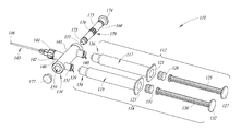
- FIG. 2 is an exploded view of the syringe of FIG. 1 .
- FIG. 3 is a cross-sectional view of the syringe of FIG. 1 taken along lines 3 - 3 , illustrating the syringe in a withdrawal configuration.
- FIG. 3A is a detail view of the syringe of FIG. 1 , illustrating a slider disposed in a hub in a withdrawal position.
- FIG. 4 is a cross-sectional view of the syringe of FIG. 1 taken along lines 4 - 4 , illustrating the syringe in a neutral configuration.
- FIG. 4A is a detail view of the syringe of FIG. 1 , illustrating a slider disposed in a hub in a neutral position.
- FIG. 5 is a cross-sectional view of the syringe of FIG. 1 taken along lines 5 - 5 , illustrating the syringe in an injection configuration.
- FIG. 5A is a detail view of the syringe of FIG. 1 , illustrating a slider disposed in the hub in an injection position.
- FIG. 6A is an exploded view of a syringe, according to one implementation.
- FIG. 6B is a cross-sectional view of the syringe of FIG. 6A , illustrating the syringe in a withdrawal configuration.
- FIGS. 1 through 5B illustrate a syringe 10 , according to one example implementation.
- the syringe 10 may, for example, be used to provide intra-articular injections.
- the syringe 10 may be used to determine where a needle tip is currently positioned within a three-dimensional structure of a joint and to deliver an injectable fluid to a desired location, such as an intra-articular location.
- the syringe 10 may be used to apply injections in an intrathecal space where fluid withdrawal may be required and precise positioning of the needle tip to deliver an injectable fluid may also be required.
- the syringe 10 may be used to implement complex procedures where minimal movement of the syringe 10 may be required along with fluid withdrawal and delivery of an injectable fluid, such as ophthalmic injections, intracerebral injections, and otolaryngological procedures.
- the injectable fluid may include a therapeutic agent (e.g., an Active Pharmaceutical Agent, such as corticosteroid, hyaluronic acid or a biologic).
- the injectable fluid may include a diagnostic agent, such as X-ray-contrast preparations, radioactive isotopes, and/or dyes.
- the injectable fluid may include a combination of a therapeutic agent and a diagnostic agent.
- the injectable fluid may further include excipients or other pharmaceutically inactive substances formulated with the therapeutic agent and/or diagnostic agents.
- the syringe 10 includes a withdrawal chamber barrel 12 and an injectable fluid chamber barrel 14 .
- the barrels 12 , 14 each have a respective interior space or lumen 17 , 19 .
- the withdrawal chamber barrel 12 and the injectable fluid chamber barrel 14 may be formed of transparent or translucent materials, such as clear plastic or glass, to allow a user to view the interior of the withdrawal chamber and injectable fluid chamber barrels 12 , 14 .
- the withdrawal chamber and injectable fluid chamber barrels 12 , 14 may include graduation markings to allow the user to view a fluid against the graduation markings to assess the volume of fluid in the respective chamber barrels 12 , 14 .
- An upper end of the withdrawal chamber barrel 12 optionally includes a finger flange 21 that extends peripherally around an upper end of the withdrawal chamber barrel 12 .
- the finger flange 21 of the withdrawal chamber barrel 12 has a substantially rectangular shape.
- the finger flange 21 may have any other shape, such as cylindrical, hexagonal, square, oval, etc. The finger flange 21 assists a user by providing a gripping surface during use.
- An upper end of the injectable fluid chamber barrel 14 optionally includes a finger flange 23 that extends peripherally around an upper end of the injectable fluid chamber barrel 14 .
- the finger flange 23 of the injectable fluid chamber barrel 14 has a substantially rectangular shape.
- the finger flange 23 may have any other shape, such as circular, hexagonal, square, oval, etc.
- the finger flange 23 also assists a user by providing a gripping surface during use.
- the syringe 10 includes a first plunger 25 and a head or plunger seal 26 at a lower end of the first plunger 25 .
- the first plunger 25 is partially received in the withdrawal chamber lumen 17 of the withdrawal chamber barrel 12 .
- the plunger seal 26 sealingly engages with an interior surface of the withdrawal chamber barrel 12 which forms the withdrawal chamber lumen 17 .
- the first plunger 25 is slideably moveable within the withdrawal chamber barrel 12 and includes a thumb rest 27 . The sealing engagement of the plunger seal 26 with the interior surface of the withdrawal chamber barrel 12 creates a vacuum in the withdrawal chamber barrel lumen 17 in response to movement of the first plunger 25 .
- the vacuum created in the withdrawal chamber barrel lumen 17 facilitates creating a pressure differential to draw fluid toward the withdrawal chamber barrel lumen 17 in response to distal movement of the first plunger 25 .
- the withdrawal chamber barrel 12 can be coupled to a source of fluid, such as, for example, an intra-articular joint of a patient. Distal movement of the first plunger 25 relative to the lower end of the withdrawal chamber barrel 12 creates a negative relative pressure or vacuum in the withdrawal chamber lumen 17 to draw the fluid toward the withdrawal chamber lumen 17 from the source of fluid.
- the plunger seal 26 may, for instance, be made from rubber or a resilient, conformable polymer, such as an elastomer.
- the syringe 10 also includes a second plunger 30 and a head or plunger seal 31 at a lower end of the second plunger 30 .
- the second plunger 30 is partially received in the injectable fluid chamber lumen 19 of the injectable fluid chamber barrel 14 .
- the plunger seal 31 sealingly engages with an interior surface of the injectable fluid chamber barrel 14 which forms the injectable fluid chamber lumen 19 .
- the second plunger 30 is slideably moveable within the injectable fluid chamber barrel 14 and includes a thumb rest 32 . The sealing engagement of the plunger seal 31 with the interior surface of the injectable fluid chamber barrel 14 creates a vacuum in the injectable fluid chamber barrel lumen 19 in response to movement of the second plunger 30 .
- the vacuum created in the injectable fluid chamber barrel lumen 19 facilitates creating a pressure differential to draw fluid in the injectable fluid chamber lumen 19 in response to distal movement of the second plunger 30 .
- the injectable fluid chamber barrel 14 can be coupled to a bottle, bolus, or other source of fluid to draw the injectable fluid, such as, for example, medicant(s) contained in the bottle.
- the injectable fluid can be pre-loaded in the injectable fluid chamber barrel 14 prior to delivery to a user, for example, a healthcare provider.
- the medicant(s) can include a therapeutic agent (e.g., an Active Pharmaceutical Agent, such as corticosteroid, hyaluronic acid or a biologic).
- the injectable fluid may include a diagnostic agent, such as X-ray-contrast preparations, radioactive isotopes, and/or dyes.
- the injectable fluid can include a combination of a therapeutic agent and a diagnostic agent.
- the injectable fluid may further include excipients or other pharmaceutically inactive substances formulated with the therapeutic agent and/or diagnostic agents.
- the plunger seal 31 may, for instance, be made from rubber or a resilient, conformable polymer, such as an elastomer.
- the withdrawal chamber barrel 12 and the injectable fluid chamber barrel 14 are detachably coupleable to a communal hub 34 .
- the syringe 10 includes coupling adapters 35 , 36 , for example, in the form of female and male Luer-Lock portions, which directly or indirectly couple the withdrawal chamber and the injectable fluid chamber barrels 12 , 14 to the communal hub 34 .
- Female couplers for example, in the form of female Luer-Lock portions, are located at respective lower ends of the withdrawal chamber barrel 12 and the injectable fluid chamber barrel 14 .
- Male coupler 51 for example, in the form of a male Luer-Lock portion, is located at a lower end of the communal hub 34 proximal to an injectable fluid chamber fluid port 39 which provides a fluidly communicative path to the injection chamber barrel lumen 19 .
- Male coupler 50 for example, in the form of a male Luer-Lock portion is located at a lower end of a test indicator housing 63 which provides a fluidly communicative path to the withdrawal chamber barrel lumen 17 .
- the male Luer-Lock portions are physically detachably coupleable to corresponding female Luer-Lock portions. In this manner, the withdrawal chamber barrel 12 and/or the injectable fluid chamber barrel 14 may each be selectively detachable from the syringe 10 .
- the communal hub 34 includes a needle portion 40 and a slider portion 41 .
- the needle portion 40 includes one or more needle ports 42 through which a needle 43 is coupled to the communal hub 34 .
- the one or more needle ports 42 may be formed by or part of a Luer-Lock connector or coupler.
- the needle port 42 may be part of a male Luer-Lock portion and the needle 43 may include a female Luer-Lock portion that detachably rotatingly couples with the male Luer-Lock portion.
- the communal hub 34 may include a slip-tip, an eccentric tip, or other types of needle adapters to couple the communal hub 34 to the needle 43 .
- the coupler or connector that forms a Luer-Lock connection may be integrally formed with the communal hub 34 as a unitary, single piece.
- the needle 43 includes a needle hub 44 and a needle shaft 47 .
- the needle hub 44 may be integrally formed with the communal hub 34 as a unitary, single piece.
- the needle shaft 47 includes a beveled end or point or tip 48 , and includes a lumen extending therethrough.
- the needle 43 is fluidly communicatively coupled to the syringe 10 to withdraw or expel fluid when administering to a patient.
- the slider portion 41 of the communal hub 34 is substantially cylindrical shaped and hollow, and defines an opening 59 to receive a slider 60 , as discussed in more detail below.
- the slider portion 41 includes a first port 61 in fluid communication with the needle port 42 and the withdrawal chamber fluid port 37 disposed in the connector 95 and the injectable fluid chamber fluid port 39 disposed in the male coupler 51 .
- the male coupler 51 is sized and shaped to couple to or with the injectable fluid chamber barrel 14 .
- the male coupler 50 couples the test indicator housing 63 to or with the withdrawal chamber barrel 12 .
- the test indicator housing 63 is sized and shaped to couple to or with the communal hub 34 .
- the communal hub 34 includes the connector 95 which can couple to or with the test indicator housing 63 via welded structures, snap fit structures, adhesives, or other suitable connecting structures.
- the test indicator housing 63 can be coupled to the communal hub 34 and the withdrawal chamber barrel 12 via Luer-Lock couplers or connectors.
- the test indicator housing 63 is substantially cylindrical shaped and hollow to define a test indicator chamber 64 .
- the test indicator chamber 64 is sized and shaped to house a test indicator 65 and a one-way valve 66 .
- the test indicator 65 typically provides a visual indication (e.g., appearance of line, change of color) when contacted by a defined substance.
- the test indicator 65 is located in the test indicator chamber 64 so as to be contacted by fluid drawn into the withdrawal chamber lumen 17 via operation of the first plunger 25 .
- the test indicator 65 may take the form of a test strip that is removably received in the test indicator chamber 64 .
- the test indicator 65 can take the form of a cylindrical shaped test strip, rectangular shaped test strip, or any other shape or form of test strip which is formed of material (e.g., lateral flow strip) with one or more substances (e.g., reagents) that react in a defined manner (e.g., change color) in the presence of defined substances (e.g., protein, glucose, etc.).
- substances e.g., reagents
- the one-way valve 66 is disposed in the test indicator chamber 64 and is fluidly coupled to the withdrawal chamber fluid port 37 .
- the one-way valve 66 allows flow of fluids in one direction, i.e., into the withdrawal chamber barrel 12 , and prevents flow of fluids out of the withdrawal chamber barrel 12 into the opening 59 , or internal pathways beneath the one-way valve 66 . In this manner, the one-way valve 66 can prevent and/or avoid any cross-contamination of fluids flowing out of the withdrawal chamber barrel 12 and flowing into the injection chamber barrel 14 .
- the one-way valve 66 may be duckbill valves, check valves, ball valves, butterfly valves, cross-slit valves, umbrella valves, or the like.
- the illustrated embodiment of FIGS. 1-5B includes a check valve that is positioned in the test indicator chamber 64 .
- the slider portion 41 of the communal hub 34 includes the opening 59 to receive the slider 60 .
- the slider 60 includes a first portion 70 , a second portion 71 , and a pin 72 , or other suitable alignment structures.
- the slider 60 includes separate first portion 70 and second portion 71 which are coupled together to facilitate ease of assembly and manufacturing.
- the first portion 70 is received through the opening 59 from one end of the opening 59 while the second portion 71 is received through the opening 59 from the other end of the opening 59 .
- the first portion 70 is coupled to the second portion 71 .
- the first portion 70 and the second portion 71 can be coupled to each other via a snap fit structure, adhesive, ultrasonic welding, or other suitable coupling structures.
- the first portion 70 includes a shaft portion 73 and a cap portion 74 extending from one end of the shaft portion 73 .
- the shaft portion 73 includes at least a pair of slider grooves 75 which extend around a periphery of an outer surface of the shaft portion 73 .
- the slider grooves 75 are sized and shaped to receive seal devices 76 a , such as, for example, O-rings.
- the seal devices 76 a are sized and shaped to provide a frictional fit between the first portion 70 and an interior surface of the slider portion 41 of the communal hub 34 .
- Such frictional forces will at least be higher than the gravitational forces which will prevent the slider 60 from translating due to gravitational forces.
- a user may depress the cap portion 74 with a force sufficient to overcome the frictional forces provided by the sealing engagement of the seal devices 76 a with the interior surface of the slider portion 41 .
- the slider 60 is disposed in the opening 59 of the communal hub 34 .
- the shaft portion 73 of the first portion 70 is sized and shaped to define a relatively small gap D between an outer surface of the shaft portion 73 and an interior surface of the slider portion 41 .
- the gap D may have a range of between 100 to 500 microns.
- the gap D may be sized to provide sufficient area to allow fluid flow while minimizing fluid losses to improve efficiency.
- the gap D defines a flow path for the fluid drawn into the communal hub 34 to flow around the outer surface of the shaft portion 73 to the withdrawal chamber barrel lumen 17 .
- the cap portion 74 of the first portion 70 is sized and shaped to have an external outer diameter which is greater than the outer diameter of the shaft portion 73 .
- the cap portion 74 of the first portion 70 is sized and shaped to have an outer diameter which exceeds an outer diameter of the opening 59 disposed in the slider portion 41 .
- an inner surface of the cap portion 74 of the first portion 70 mates with an outer surface of the slider portion 41 to act as a stop when the slider 60 is received in the opening 59 and is in the first position ( FIGS. 3 and 3A ).
- the second portion 71 also includes a shaft portion 77 and a cap portion 78 extending from one end of the shaft portion 77 .
- the shaft portion 77 of the second portion 71 also includes at least a pair of slider grooves 79 which extend around a periphery of an outer surface of the shaft portion 77 .
- the slider grooves 79 are sized and shaped to receive seal devices 76 b , such as, for example, O-rings.
- the seal devices 76 b are sized and shaped to provide a frictional fit between the second portion 71 and the interior surface of the slider portion 41 .
- Such frictional forces will at least be higher than the gravitational forces which will prevent the slider 60 from translating due to gravitational forces.
- a user may depress the cap portion 78 with a force sufficient to overcome the frictional forces provided by the sealing engagement of the seal devices 76 b with the interior surface of the slider portion 41 .
- the slider 60 is disposed in the opening 59 of the communal hub 34 . More particularly, the shaft portion 77 of the second portion 71 is also sized and shaped to define a relatively small gap D between an outer surface of the shaft portion and an interior surface of the slider portion 41 .
- the gap D defines a flow path for the fluid expelled from the injectable fluid chamber barrel 14 to flow around the outer surface of the shaft portion 77 to the first port 61 .
- the cap portion 78 of the second portion 71 is sized and shaped to have an external outer diameter which is greater than the outer diameter of the shaft portion 77 .
- the cap portion 78 of the second portion 71 is sized and shaped to have an outer diameter which exceeds an outer diameter of the opening 59 disposed in the slider portion 41 .
- an inner surface of the cap portion 78 of the second portion 71 mates with an outer surface of the slider portion 41 to act as a stop when the slider 60 is received in the opening 59 and is in the second position ( FIGS. 5 and 5A ).
- Both the first portion 70 and the second portion 71 include a respective pin opening 81 which partially extends through the respective shaft portions 73 , 77 .
- the pin openings 81 of the first portion 70 and the second portion 71 extend from ends which are opposite to ends which include the respective cap portions 74 , 78 .
- the pin openings 81 are sized and shaped to receive therein the pin 72 .
- FIGS. 3-5B illustrate the syringe 10 in various configurations.
- the syringe 10 can be in a testing, withdrawing, or withdrawal configuration ( FIGS. 3 and 3A ), a neutral configuration ( FIGS. 4 and 4A ), and an injection configuration ( FIGS. 5 and 5A ).
- the slider 60 can translate between a withdrawal position which allows flow of fluid into the withdrawal chamber barrel lumen 17 and prevents flow of fluid in or out of the injection chamber barrel lumen 19 , a neutral position which prevents flow of fluid from or into the withdrawal chamber barrel lumen 17 and the injection chamber barrel lumen 19 , and an injection position which allows flow out of the injection chamber barrel lumen 19 and prevents flow of fluid into or out of the withdrawal chamber barrel lumen 17 .
- the slider 60 is disposed in the opening 59 of the communal hub 34 to translate between the different positions, e.g., withdrawal, neutral, and/or injection positions, in a direction which is substantially perpendicular to a flow path of fluid drawn into the communal hub 34 via the needle 43 and expelled from the communal hub 34 via the needle 43 , as indicated by arrow 84 .
- the direction of translation of the slider 60 may also be perpendicular to flow paths of fluid in the withdrawal chamber barrel lumen 17 and out of the injection chamber barrel lumen 19 .
- FIGS. 3 and 3A illustrate the syringe 10 in a withdrawal configuration and, more specifically, FIG. 3A illustrates a detail view of the communal hub 34 and the slider 60 , with certain components removed for clarity of description and illustration.
- the slider 60 in the withdrawal configuration, the slider 60 is in the withdrawal position, where the inner surface of the cap portion 74 of the first portion 70 abuts or mates with the outer surface of the slider portion 41 .
- the seal devices 76 a in the first portion 70 of the slider 60 are positioned to open a flow path from the needle port 42 disposed in the communal hub 34 to the withdrawal chamber fluid port 37 as indicated by arrow 88
- the seal devices 76 b in the second portion 71 of the slider 60 are positioned to block a flow path from the needle port 42 disposed in the communal hub 34 to the injectable fluid chamber fluid port 39 .
- the seal devices 76 a prevent the flow from traversing into the second portion 71 of the slider 60 . In this manner, a user can draw fluid from joint spaces, such as fluids found in joints of a body, for example, synovial fluid.
- Synovial fluids have a high concentration of protein.
- the user may withdraw the first plunger 25 to withdraw fluid, e.g., fluid found in joint spaces, and receive at least some of such fluid in the withdrawal chamber barrel lumen 17 .
- fluid e.g., fluid found in joint spaces
- other applications such as, for example, injections into an intrathecal space, ophthalmic injections, intracerebral injections, and otolaryngological procedures are also within the scope of the disclosed subject matter.
- the pressure differential created in the withdrawal chamber barrel lumen 17 and the communal hub 34 in particular, the negative relative pressure or vacuum in the withdrawal chamber barrel lumen 17 —draws fluid toward the withdrawal chamber barrel lumen 17 and into the test indicator chamber 64 , which exposes the test indicator 65 to the fluid.
- FIGS. 4 and 4A illustrate the syringe 10 in a neutral configuration and, more specifically, FIG. 4A illustrates a detail view of the communal hub 34 and the slider 60 , with certain components removed for clarity of description and illustration.
- the slider 60 in the neutral configuration, is in a transition position relatively between the withdrawal and injection positions ( FIGS. 3, 3A, 5, 5A ).
- the seal devices 76 a in the first portion 70 of the slider 60 and the seal devices 76 b in the second portion 71 of the slider 60 are positioned to block a flow path from the needle port 42 disposed in the communal hub 34 to the withdrawal chamber fluid port 37 and the flow path from the needle port 42 disposed in the communal hub 34 to the injectable fluid chamber port 39 .
- fluid may not flow into or out of the injection barrel lumen 19 and the withdrawal chamber barrel lumen 17 .
- FIGS. 5 and 5A illustrate the syringe 10 in an injection configuration and, more specifically, FIG. 5A illustrates a detail view of the communal hub 34 and the slider 60 , with certain components removed for clarity of description and illustration.
- the slider 60 in the injection configuration, is in the injection position, where the inner surface of the cap portion 78 of the second portion 71 abuts or mates with the outer surface of the slider portion 41 .
- the seal devices 76 b in the second portion 71 of the slider 60 are positioned to open a flow path from the injection fluid chamber port 39 to the needle port 42 disposed in the communal hub 34 as indicated by arrow 89 , while the seal devices 76 a in the first portion 70 of the slider 60 are positioned to block a flow path from the needle port 42 disposed in the communal hub 34 to the withdrawal chamber fluid port 37 .
- the seal devices 76 b prevent the flow from traversing into the first portion 70 of the slider 60 .
- fluid for example, medicant(s)
- the user may initially fill the injectable fluid chamber lumen 19 with fluid, e.g., medicant(s), from a bottle or other source of medicant(s).
- the injectable fluid chamber lumen 19 may be preloaded with fluid, e.g., medicant(s).
- the user may then withdraw fluid from the affected joints. For example, the user may position the slider 60 in the withdrawal position and insert the tip 48 of the needle 43 at the affected joints.
- Distal movement of the first plunger 25 creates negative relative pressure or vacuum in the withdrawal chamber barrel 12 allowing the user to withdraw fluid from the patient's joint space.
- the withdrawn fluid will flow into the withdrawal chamber barrel 12 .
- the test indicator 65 may not reach the withdrawal chamber barrel lumen 17 .
- a chemical reaction between the fluid and a substance (e.g., reagent) carried by the test indicator 65 may provide an indication (e.g., visually perceptible change) of the presence of fluids which are known to be found in joint spaces, such as, for example, bursae, which are filled with synovial fluid.
- synovial fluids have a high concentration of protein.
- test indicator 65 may comprise a reagent strip or other strips which use glucose oxidase, hexokinase, or cupric sulfate, for example, or comprise appropriate chemistry to determine the protein content or presence.
- the test indicator 65 may indicate presence of protein colorimetrically, which may be read visually or in some implementations through a reflectance photometer.
- the user may, for example, depress the cap portion 78 of the second portion 71 of the slider 60 to move the slider 60 to the injection position.
- the user may then precisely apply the injectable fluid (e.g., an Active Pharmaceutical Agent, such as corticosteroid, hyaluronic acid or a biologic), by proximally moving or depressing the second plunger 30 , which will create a positive pressure in the injectable fluid chamber barrel 14 , thus expelling the injectable fluid into the joint via the tip 48 of the needle 43 .
- an Active Pharmaceutical Agent such as corticosteroid, hyaluronic acid or a biologic
- the communal hub 34 may include markings which indicate the direction of flow.
- the markings may include an inflow mark 90 indicating flow into the withdrawal chamber barrel lumen 17 and an outflow mark 91 indicating flow out of the injection chamber barrel lumen 19 .
- the markings (e.g., 90 , 91 ) may be painted, printed, or etched on the communal hub 34 .
- a syringe 110 may omit the test indicator housing 63 .
- FIGS. 6A-B illustrate a variation of the syringe 10 of FIGS. 1-5A which excludes the test indicator housing 63 .
- the syringe 110 includes a withdrawal chamber barrel 112 and an injectable fluid chamber barrel 114 .
- the barrels 112 , 114 each have a respective interior space or lumen 117 , 119 .
- the withdrawal chamber barrel 112 and the injectable fluid chamber barrel 114 may be formed of transparent or translucent materials, such as clear plastic or glass, to allow a user to view the interior of the withdrawal chamber and injectable fluid chamber barrels 112 , 114 .
- the withdrawal chamber and injectable fluid chamber barrels 112 , 114 may include graduation markings to allow the user to view a fluid against the graduation markings to assess the volume of fluid in the respective chamber barrels 112 , 114 .
- An upper end of the withdrawal chamber barrel 112 optionally includes a finger flange 121 that extends peripherally around an upper end of the withdrawal chamber barrel 112 .
- An upper end of the injectable fluid chamber barrel 114 also optionally includes a finger flange 123 that extends peripherally around an upper end of the injectable fluid chamber barrel 114 .
- the finger flange 121 of the withdrawal chamber barrel 112 and the finger flange 123 of the injectable fluid chamber barrel 114 may have various shapes such as cylindrical, hexagonal, square, oval, etc.
- the syringe 110 includes a first plunger 125 and a head or plunger seal 126 at a lower end of the first plunger 125 .
- the first plunger 125 is partially received in the withdrawal chamber lumen 117 of the withdrawal chamber barrel 112 .
- the plunger seal 126 sealingly engages with an interior surface of the withdrawal chamber barrel 112 which forms the withdrawal chamber lumen 117 .
- the first plunger 125 is slideably moveable within the withdrawal chamber barrel 112 and includes a thumb rest 127 .
- the syringe 110 also includes a second plunger 130 and a head or plunger seal 131 at a lower end of the second plunger 130 .
- the second plunger 130 is partially received in the injectable fluid chamber lumen 119 of the injectable fluid chamber barrel 114 .
- the second plunger 130 is slideably moveable within the injectable fluid chamber barrel 114 and includes a thumb rest 132 .
- the plunger seals 126 , 131 sealingly engage with the interior surfaces of the withdrawal chamber lumen 117 and/or the injectable fluid chamber barrel lumen 119 to create the pressure differentials which allow fluid to be drawn toward the withdrawal chamber barrel lumen 117 and/or the injectable fluid chamber barrel lumen 119 through movement of the corresponding first and/or second plungers 125 , 130 . Further, as discussed above, proximal movement of second plunger 130 relative to the lower end of the injectable fluid chamber barrel 114 creates a positive pressure to expel the fluid in the injectable fluid chamber barrel lumen 119 .
- the withdrawal chamber barrel 112 and the injectable fluid chamber barrel 114 are detachably coupleable to a communal hub 134 .
- the syringe 110 includes coupling adapters 136 , for example, in the form of female and male Luer-Lock portions, which directly or indirectly couple the withdrawal chamber and the injectable fluid chamber barrels 112 , 114 to the communal hub 134 .
- Female couplers for example, in the form of female Luer-Lock portions, are located at respective lower ends of the withdrawal chamber barrel 112 and the injectable fluid chamber barrel 114 .
- Male couplers 151 are located at lower ends of the communal hub 134 proximal to corresponding injectable fluid chamber fluid port 139 and withdrawal chamber barrel fluid port 140 .
- the injectable fluid chamber fluid port 139 and the withdrawal chamber barrel fluid port 140 provide a fluidly communicative path to the injection chamber barrel lumen 119 and the withdrawal chamber barrel lumen 117 , respectively.
- the male Luer-Lock portions are physically detachably coupleable to corresponding female Luer-Lock portions.
- the communal hub 134 includes a needle portion 140 and a slider portion 141 .
- the needle portion 140 includes one or more needle ports 142 via which a needle 143 is coupled to the communal hub 134 .
- the one or more needle ports 142 may be formed by or part of a Luer-Lock connector or coupler.
- the needle 143 includes a needle hub 144 and a needle shaft 147 .
- the needle hub 144 may be integral with the communal hub 134 as a unitary, single piece.
- the needle shaft 147 includes a beveled end or point or tip 148 , and includes a lumen extending therethrough.
- the needle 143 is fluidly communicatively coupled to the syringe 110 to withdraw or expel fluid when administering to a patient.
- the slider portion 141 of the communal hub 134 is substantially cylindrical shaped and hollow, and defines an opening 159 to receive a slider 160 .
- the slider portion 141 includes a first port 161 in fluid communication with the needle port 142 and the withdrawal chamber fluid port 140 and the injectable fluid chamber fluid port 139 .
- the slider 160 in this implementation, includes a shaft portion 173 extending from a cap portion 174 .
- the cap portion 174 is sized and shaped to have an external outer diameter which is greater than the outer diameter of the shaft portion 173 .
- the shaft portion 173 includes a tapered portion 175 which couples to a coupling cap portion 177 .
- the coupling cap portion 177 has an external outer diameter which is greater than the outer diameter of the shaft portion 173 .
- cap portion 174 and the coupling cap portion 177 sized and shaped in this manner allows the cap portion 174 and the coupling cap portion 177 to act as a stop when the slider 161 is moved between its extreme positions and indicate to a user if the syringe 110 is in a withdrawal configuration or an injection configuration.
- the shaft portion 173 includes a plurality of slider grooves 179 which extend around a periphery of an outer surface of the shaft portion 173 .
- a first pair of slider grooves 179 are spaced apart in an axial direction and a second pair of slider grooves 179 are spaced apart in the axial direction.
- the slider grooves 179 are sized and shaped to receive seal devices 176 , such as, for example, O-rings.
- a first pair of seal devices 176 are received in the first pair of slider grooves 179 to provide a first chamber, and a second pair of seal devices 176 are received in the second pair of slider grooves 179 to provide a second chamber.
- the seal devices 176 are sized and shaped to provide a frictional fit between the shaft portion 173 and an interior surface of the slider portion 141 of the communal hub 134 . Again, such frictional forces will at least be higher than the gravitational forces which will prevent the slider 160 from translating due to gravitational forces. Thus, in order to move or translate the slider, a user may depress the cap portion 174 or the coupling cap portion 177 with a force sufficient to overcome the frictional forces provided by the sealing engagement of the seal devices 176 with the interior surface of the slider portion 141 .
- the slider 160 is disposed in the opening 159 of the communal hub 134 .
- the shaft portion 173 is sized and shaped to define a relatively small gap D between an outer surface of the shaft portion 173 and an interior surface of the slider portion 141 .
- the gap D is provided in the first chamber between the first pair of seal devices 176 and in the second chamber between the second pair of seal devices 176 .
- the gap D may have a range of between 100 to 500 microns.
- the gap D may be sized to provide sufficient area to allow fluid flow while minimizing fluid losses to improve efficiency.
- the gap D defines a flow path for the fluid drawn into the communal hub 134 or expelled from the communal hub 134 to flow around the outer surface of the shaft portion 173 .
- the slider 160 is disposed in the opening 159 to translate between different positions, e.g., withdrawal, neutral, and/or injection positions, in a direction which is substantially perpendicular to a flow path of fluid drawn into the communal hub 134 via the needle 143 and expelled from the communal hub 134 via the needle 143 .
- FIG. 6B illustrates the slider 160 in the withdrawal position.
- the seal devices 176 are positioned to open a flow path from the needle port 142 through the withdrawal chamber barrel fluid port 140 into the withdrawal chamber barrel lumen 117 , while closing the flow path to the injection chamber barrel lumen 119 by preventing the flow from traversing the centrally positioned seal devices 176 and entering the injection chamber barrel lumen 119 .
- the slider 160 similar to the discussion above with reference to FIGS. 4, 4A also can be in a neutral position.
- the seal devices 176 are positioned to prevent fluid flow into or out of the injection chamber barrel lumen 119 and the withdrawal chamber barrel lumen 117 .
- the syringe 110 when the syringe 110 is in the neutral position, as the injection chamber barrel lumen 119 and the withdrawal barrel chamber lumen 117 are restricted from receiving any fluid from the needle 143 , such prevents or mitigates cross-contamination, as only one of the withdrawal chamber barrel 112 or the injection chamber barrel 114 can be used concurrently.
- the slider 160 similar to the discussion above with reference to FIGS. 5A, 5B also can be in an injection position.
- an inner surface of the cap portion 177 abuts or mates with the outer surface of the slider portion 141 .
- the seal devices 176 are positioned to open a flow path from the injection fluid chamber port 139 to the needle port 142 , while closing the flow path to the withdrawal chamber barrel lumen 117 by preventing the flow from traversing the centrally positioned seal devices 176 and entering the withdrawal chamber barrel lumen 117 .
- the various components described herein may advantageously be provided as a kit.
- the kit may, for example, include a communal hub with a test indicator.
- the test indicator may include a material with one or more substances (e.g., reagents) that react in a defined manner (e.g., change color) in the presence of defined substances.
- the communal hub may include a mechanism, such as, for example, the various implementations of the slider described herein, that are operable to selectively provide one or more fluidly communicative paths.
- the communal hub may include adapters such that the communal hub is coupleable to a needle and chamber barrels.
- the kit may also include withdrawal chamber and injectable fluid chamber barrels to precisely confirm and administer injectable fluids to the affected areas.
- the kit may only include a communal hub, test indicator, and a withdrawal chamber barrel.
- the injectable fluid barrel may be supplied by the user.
- the kit may also include injectable fluids or medicant(s) that are being administered at the affected areas and needles.
- the kit may also include a set of instructions for effective use of the syringe.
- a method to use the various implementations of the syringes described herein may include filling an injectable fluid chamber lumen of an injectable fluid chamber barrel with a medicant(s).
- the injectable fluid chamber barrel may then be coupled to a communal hub, according to one or more implementations of the communal hubs described herein, via coupling adapters, for example, Luer Locks.
- the method may include coupling an empty withdrawal chamber barrel to the communal hub via coupling adapters, for example, Luer Locks.
- a plunger of the withdrawal chamber barrel may be in a fully or at least partially depressed position.
- the method may include coupling a needle to the communal hub via, for example, Luer Locks.
- the method may further include inserting a needle into bodily tissue of a patient, for example, at intra-articular locations.
- the method may include withdrawing the plunger of the withdrawal chamber barrel to draw fluid from the patient, for example, synovial fluid, so the fluid is drawn into a chamber disposed in the communal hub that houses a test indicator.
- the operator of the syringe may wait to observe if the test indicator responds in a defined manner. In some implementations, if no response is observed the operator may remove and discard the withdrawal chamber barrel and couple another withdrawal chamber barrel. In some implementations, the operator may continue manipulating the syringe until a response of the test indicator is observed.
- the operator may depress the slider to move the slider to the injection position.
- the operator may thereafter depress the plunger of the injectable fluid chamber barrel to inject the medicant(s).
- the method may further include removing the syringe from the patient. In some implementations, the removed syringe may be discarded or disposed.
Landscapes
- Health & Medical Sciences (AREA)
- Heart & Thoracic Surgery (AREA)
- Hematology (AREA)
- Anesthesiology (AREA)
- Biomedical Technology (AREA)
- Engineering & Computer Science (AREA)
- Life Sciences & Earth Sciences (AREA)
- Animal Behavior & Ethology (AREA)
- General Health & Medical Sciences (AREA)
- Public Health (AREA)
- Veterinary Medicine (AREA)
- Vascular Medicine (AREA)
- Pulmonology (AREA)
- Infusion, Injection, And Reservoir Apparatuses (AREA)
Abstract
Description
Claims (37)
Priority Applications (3)
| Application Number | Priority Date | Filing Date | Title |
|---|---|---|---|
| US15/491,730 US10328212B2 (en) | 2016-04-22 | 2017-04-19 | Single slider double barrel syringe and method to use same for medical diagnostics, therapeutic use, and placement confirmation and joint space injection |
| US16/407,955 US20190269860A1 (en) | 2016-04-22 | 2019-05-09 | Single slider double barrel syringe and method to use same for medical diagnostics, therapeutic use, and placement confirmation and joint space injection |
| US16/407,945 US20190262547A1 (en) | 2016-04-22 | 2019-05-09 | Single slider double barrel syringe and method to use same for medical diagnostics, therapeutic use, and placement confirmation and joint space injection |
Applications Claiming Priority (3)
| Application Number | Priority Date | Filing Date | Title |
|---|---|---|---|
| US201662326597P | 2016-04-22 | 2016-04-22 | |
| US201662401618P | 2016-09-29 | 2016-09-29 | |
| US15/491,730 US10328212B2 (en) | 2016-04-22 | 2017-04-19 | Single slider double barrel syringe and method to use same for medical diagnostics, therapeutic use, and placement confirmation and joint space injection |
Related Child Applications (2)
| Application Number | Title | Priority Date | Filing Date |
|---|---|---|---|
| US16/407,955 Division US20190269860A1 (en) | 2016-04-22 | 2019-05-09 | Single slider double barrel syringe and method to use same for medical diagnostics, therapeutic use, and placement confirmation and joint space injection |
| US16/407,945 Continuation US20190262547A1 (en) | 2016-04-22 | 2019-05-09 | Single slider double barrel syringe and method to use same for medical diagnostics, therapeutic use, and placement confirmation and joint space injection |
Publications (2)
| Publication Number | Publication Date |
|---|---|
| US20170304553A1 US20170304553A1 (en) | 2017-10-26 |
| US10328212B2 true US10328212B2 (en) | 2019-06-25 |
Family
ID=58672704
Family Applications (3)
| Application Number | Title | Priority Date | Filing Date |
|---|---|---|---|
| US15/491,730 Active 2037-04-29 US10328212B2 (en) | 2016-04-22 | 2017-04-19 | Single slider double barrel syringe and method to use same for medical diagnostics, therapeutic use, and placement confirmation and joint space injection |
| US16/407,945 Abandoned US20190262547A1 (en) | 2016-04-22 | 2019-05-09 | Single slider double barrel syringe and method to use same for medical diagnostics, therapeutic use, and placement confirmation and joint space injection |
| US16/407,955 Abandoned US20190269860A1 (en) | 2016-04-22 | 2019-05-09 | Single slider double barrel syringe and method to use same for medical diagnostics, therapeutic use, and placement confirmation and joint space injection |
Family Applications After (2)
| Application Number | Title | Priority Date | Filing Date |
|---|---|---|---|
| US16/407,945 Abandoned US20190262547A1 (en) | 2016-04-22 | 2019-05-09 | Single slider double barrel syringe and method to use same for medical diagnostics, therapeutic use, and placement confirmation and joint space injection |
| US16/407,955 Abandoned US20190269860A1 (en) | 2016-04-22 | 2019-05-09 | Single slider double barrel syringe and method to use same for medical diagnostics, therapeutic use, and placement confirmation and joint space injection |
Country Status (5)
| Country | Link |
|---|---|
| US (3) | US10328212B2 (en) |
| EP (1) | EP3445426B1 (en) |
| AU (1) | AU2017252645A1 (en) |
| CA (1) | CA3019843C (en) |
| WO (1) | WO2017184755A1 (en) |
Families Citing this family (9)
| Publication number | Priority date | Publication date | Assignee | Title |
|---|---|---|---|---|
| WO2019055497A1 (en) * | 2017-09-13 | 2019-03-21 | Bayer Healthcare Llc | Sliding syringe cap for separate filling and delivery |
| GB201810324D0 (en) * | 2018-06-22 | 2018-08-08 | Leeds Teaching Hospital Nhs Trust | Fluid delivery system |
| KR102709338B1 (en) * | 2018-08-06 | 2024-09-25 | 이태이 초워스 | Multi-lumen syringe for intraocular injections |
| US12005130B2 (en) | 2019-10-16 | 2024-06-11 | Agitated Solutions Inc. | Generating microbubbles for bubble studies |
| NL2024277B1 (en) * | 2019-11-21 | 2021-08-11 | Imcomet B V | Interstitial fluid removal device |
| FR3109318B1 (en) * | 2020-04-15 | 2023-11-10 | Syrengy | Injection syringe |
| US20230191028A1 (en) * | 2021-10-22 | 2023-06-22 | Boston Scientific Medical Device Limited | Systems and methods for producing mixtures |
| WO2024113180A1 (en) * | 2022-11-29 | 2024-06-06 | 天津大学 | Radioactive medicament injection device and working method therefor |
| CN116077759B (en) * | 2022-11-29 | 2023-09-26 | 天津大学 | Radiopharmaceutical injection device and working method thereof |
Citations (26)
| Publication number | Priority date | Publication date | Assignee | Title |
|---|---|---|---|---|
| US2496559A (en) | 1945-09-17 | 1950-02-07 | Piechaczek Alojzy | Surgical and medical syringes |
| US3678959A (en) * | 1970-07-30 | 1972-07-25 | Richard B Liposky | Hand operable selector valve |
| US3749084A (en) | 1971-05-03 | 1973-07-31 | A Cucchiara | Sequentially dispensing syringe with multiple needle assembly |
| US4044757A (en) | 1976-01-14 | 1977-08-30 | The Kendall Company | Cholangiography device and method |
| US4610666A (en) * | 1985-06-24 | 1986-09-09 | Pizzino Joanne L | Dual syringe |
| EP0210160A1 (en) | 1985-06-20 | 1987-01-28 | IMMUNO Aktiengesellschaft für chemisch-medizinische Produkte | Device for applying a tissue adhesive |
| EP0312394A2 (en) | 1987-10-16 | 1989-04-19 | Quadra Logic Technologies Inc. | Membrane-supported immunoassays |
| US4979942A (en) | 1989-10-16 | 1990-12-25 | Johnson & Johnson Medical, Inc. | Two component syringe delivery system |
| DE4039522C1 (en) | 1990-12-11 | 1992-04-23 | Mannesmann Rexroth Gmbh, 8770 Lohr, De | |
| US5339829A (en) | 1989-09-21 | 1994-08-23 | Epitope, Inc. | Oral collection device |
| WO1997006428A1 (en) | 1995-08-10 | 1997-02-20 | Poole Brent W | Handheld liquid test device |
| US5944054A (en) * | 1998-01-14 | 1999-08-31 | Saieva; Carl J. | Valve for breathing systems |
| US6126644A (en) | 1996-11-29 | 2000-10-03 | Seikagaku Kogyo Kabushiki Kaisha | Holder for a syringe and an injection device using the holder |
| WO2001097881A1 (en) | 2000-06-16 | 2001-12-27 | Twardowski Zbylut J | Method and apparatus for locking of central-vein catheters |
| WO2007035621A1 (en) | 2005-09-16 | 2007-03-29 | (Osi) Eyetech, Inc. | Ophthalmic syringe |
| WO2007149980A2 (en) | 2006-06-21 | 2007-12-27 | C K Dalebout Enterprise Llc | Systems, methods, and devices for sampling bodily fluid |
| US20080167621A1 (en) | 2005-05-16 | 2008-07-10 | Wagner Gary S | Multi-Barrel Syringe Having Integral Manifold |
| US20090104714A1 (en) | 2007-10-18 | 2009-04-23 | Becton, Dickinson And Company | Visual glucose sensor and methods of use thereof |
| US20090198211A1 (en) | 2008-02-06 | 2009-08-06 | Intravena, Llc | Convenience IV kits and methods of use |
| US20090198182A1 (en) | 2004-06-30 | 2009-08-06 | Jms Co., Ltd. | Member For Catheter's Position Verification Having Color Change Indicator And Catheter Having The Member For Catheter's Position Verification |
| US20100106097A1 (en) | 2008-10-29 | 2010-04-29 | Medtronic, Inc. | Drug acceptability indicator |
| US20110118659A1 (en) | 2009-11-13 | 2011-05-19 | Armand Maaskamp | Multi-port syringe assembly |
| WO2012139035A1 (en) | 2011-04-07 | 2012-10-11 | Varav Kalle | Single hand control device for ultrasound guided injections |
| US20140261082A1 (en) | 2013-03-15 | 2014-09-18 | Nordson Corporation | Apparatus and method for hydrating a particulate biomaterial with a liquid biomaterial |
| US20150112248A1 (en) | 2013-10-21 | 2015-04-23 | Accuro Technologies Inc. | Double barrel syringe and method to use same for placement confirmation and joint space injection |
| WO2017120358A1 (en) | 2016-01-06 | 2017-07-13 | Accuro Technologies Inc. | Single valve double barrel syringe and method to use same for medical diagnostics, therapeutic use, and placement confirmation and joint space injection |
-
2017
- 2017-04-19 AU AU2017252645A patent/AU2017252645A1/en not_active Abandoned
- 2017-04-19 EP EP17722233.8A patent/EP3445426B1/en active Active
- 2017-04-19 CA CA3019843A patent/CA3019843C/en active Active
- 2017-04-19 US US15/491,730 patent/US10328212B2/en active Active
- 2017-04-19 WO PCT/US2017/028395 patent/WO2017184755A1/en not_active Ceased
-
2019
- 2019-05-09 US US16/407,945 patent/US20190262547A1/en not_active Abandoned
- 2019-05-09 US US16/407,955 patent/US20190269860A1/en not_active Abandoned
Patent Citations (26)
| Publication number | Priority date | Publication date | Assignee | Title |
|---|---|---|---|---|
| US2496559A (en) | 1945-09-17 | 1950-02-07 | Piechaczek Alojzy | Surgical and medical syringes |
| US3678959A (en) * | 1970-07-30 | 1972-07-25 | Richard B Liposky | Hand operable selector valve |
| US3749084A (en) | 1971-05-03 | 1973-07-31 | A Cucchiara | Sequentially dispensing syringe with multiple needle assembly |
| US4044757A (en) | 1976-01-14 | 1977-08-30 | The Kendall Company | Cholangiography device and method |
| EP0210160A1 (en) | 1985-06-20 | 1987-01-28 | IMMUNO Aktiengesellschaft für chemisch-medizinische Produkte | Device for applying a tissue adhesive |
| US4610666A (en) * | 1985-06-24 | 1986-09-09 | Pizzino Joanne L | Dual syringe |
| EP0312394A2 (en) | 1987-10-16 | 1989-04-19 | Quadra Logic Technologies Inc. | Membrane-supported immunoassays |
| US5339829A (en) | 1989-09-21 | 1994-08-23 | Epitope, Inc. | Oral collection device |
| US4979942A (en) | 1989-10-16 | 1990-12-25 | Johnson & Johnson Medical, Inc. | Two component syringe delivery system |
| DE4039522C1 (en) | 1990-12-11 | 1992-04-23 | Mannesmann Rexroth Gmbh, 8770 Lohr, De | |
| WO1997006428A1 (en) | 1995-08-10 | 1997-02-20 | Poole Brent W | Handheld liquid test device |
| US6126644A (en) | 1996-11-29 | 2000-10-03 | Seikagaku Kogyo Kabushiki Kaisha | Holder for a syringe and an injection device using the holder |
| US5944054A (en) * | 1998-01-14 | 1999-08-31 | Saieva; Carl J. | Valve for breathing systems |
| WO2001097881A1 (en) | 2000-06-16 | 2001-12-27 | Twardowski Zbylut J | Method and apparatus for locking of central-vein catheters |
| US20090198182A1 (en) | 2004-06-30 | 2009-08-06 | Jms Co., Ltd. | Member For Catheter's Position Verification Having Color Change Indicator And Catheter Having The Member For Catheter's Position Verification |
| US20080167621A1 (en) | 2005-05-16 | 2008-07-10 | Wagner Gary S | Multi-Barrel Syringe Having Integral Manifold |
| WO2007035621A1 (en) | 2005-09-16 | 2007-03-29 | (Osi) Eyetech, Inc. | Ophthalmic syringe |
| WO2007149980A2 (en) | 2006-06-21 | 2007-12-27 | C K Dalebout Enterprise Llc | Systems, methods, and devices for sampling bodily fluid |
| US20090104714A1 (en) | 2007-10-18 | 2009-04-23 | Becton, Dickinson And Company | Visual glucose sensor and methods of use thereof |
| US20090198211A1 (en) | 2008-02-06 | 2009-08-06 | Intravena, Llc | Convenience IV kits and methods of use |
| US20100106097A1 (en) | 2008-10-29 | 2010-04-29 | Medtronic, Inc. | Drug acceptability indicator |
| US20110118659A1 (en) | 2009-11-13 | 2011-05-19 | Armand Maaskamp | Multi-port syringe assembly |
| WO2012139035A1 (en) | 2011-04-07 | 2012-10-11 | Varav Kalle | Single hand control device for ultrasound guided injections |
| US20140261082A1 (en) | 2013-03-15 | 2014-09-18 | Nordson Corporation | Apparatus and method for hydrating a particulate biomaterial with a liquid biomaterial |
| US20150112248A1 (en) | 2013-10-21 | 2015-04-23 | Accuro Technologies Inc. | Double barrel syringe and method to use same for placement confirmation and joint space injection |
| WO2017120358A1 (en) | 2016-01-06 | 2017-07-13 | Accuro Technologies Inc. | Single valve double barrel syringe and method to use same for medical diagnostics, therapeutic use, and placement confirmation and joint space injection |
Non-Patent Citations (2)
| Title |
|---|
| Cajori et al., "The chemical composition of synovial fluid in cases of joint effusion", Journal of biological chemistry, 76, 471-480. 1928. |
| Omar et al., "Preliminary results of a new test for rapid diagnosis of septic arthritis with use of leukocyte esterase and glucose reagent strips", The Journal of Bone and Joint Surgery, 96, 2032-2037. 2014. |
Also Published As
| Publication number | Publication date |
|---|---|
| WO2017184755A1 (en) | 2017-10-26 |
| US20170304553A1 (en) | 2017-10-26 |
| EP3445426A1 (en) | 2019-02-27 |
| CA3019843A1 (en) | 2017-10-26 |
| EP3445426B1 (en) | 2021-01-13 |
| AU2017252645A1 (en) | 2018-11-01 |
| CA3019843C (en) | 2023-08-01 |
| US20190262547A1 (en) | 2019-08-29 |
| US20190269860A1 (en) | 2019-09-05 |
Similar Documents
| Publication | Publication Date | Title |
|---|---|---|
| US10328212B2 (en) | Single slider double barrel syringe and method to use same for medical diagnostics, therapeutic use, and placement confirmation and joint space injection | |
| AU2014340221B2 (en) | Double barrel syringe and method to use same for placement confirmation and joint space injection | |
| EP3345640B1 (en) | Positive displacement flush syringe | |
| ES2878047T3 (en) | System for administering a fluid to a patient with reduced contamination | |
| EP2445572B1 (en) | Medical valve with improved back-pressure sealing | |
| US9044554B2 (en) | Blunt needle safety drug delivery system | |
| EP4252818A2 (en) | Radioembolization delivery device | |
| US20110118659A1 (en) | Multi-port syringe assembly | |
| US20080275403A1 (en) | Dual syringe assembly | |
| WO2017120358A1 (en) | Single valve double barrel syringe and method to use same for medical diagnostics, therapeutic use, and placement confirmation and joint space injection | |
| CN210056094U (en) | Disposable thyroid cyst fluid suction and drug injection sclerotherapy integrated device | |
| JP2021509857A (en) | Mixing vial | |
| US20220370293A1 (en) | Combined biological sampling and injection assemblies and associated devices, systems, and methods | |
| HK40003007A (en) | Single slider double barrel syringe for medical diagnostics, therapeutic use, and placement confirmation and joint space injection | |
| HK40003007B (en) | Single slider double barrel syringe for medical diagnostics, therapeutic use, and placement confirmation and joint space injection | |
| CN113080956B (en) | Blood sampling indwelling needle | |
| US20260102554A1 (en) | Swabbable valve with universal proximal connector | |
| CN103876752A (en) | Venous indwelling channel hemostix | |
| CN113080957B (en) | A kind of positive pressure sealing pipe joint and blood collection indwelling needle | |
| US20250001154A1 (en) | Single intravenous t-site and method of administration | |
| CN108904970A (en) | A kind of multipurpose medical anti-reflective stream connector |
Legal Events
| Date | Code | Title | Description |
|---|---|---|---|
| STPP | Information on status: patent application and granting procedure in general |
Free format text: NON FINAL ACTION MAILED |
|
| STPP | Information on status: patent application and granting procedure in general |
Free format text: RESPONSE TO NON-FINAL OFFICE ACTION ENTERED AND FORWARDED TO EXAMINER |
|
| STPP | Information on status: patent application and granting procedure in general |
Free format text: NOTICE OF ALLOWANCE MAILED -- APPLICATION RECEIVED IN OFFICE OF PUBLICATIONS Free format text: AWAITING TC RESP., ISSUE FEE NOT PAID |
|
| STPP | Information on status: patent application and granting procedure in general |
Free format text: PUBLICATIONS -- ISSUE FEE PAYMENT VERIFIED |
|
| STCF | Information on status: patent grant |
Free format text: PATENTED CASE |
|
| AS | Assignment |
Owner name: ELCAM MEDICAL ACS LTD., ISRAEL Free format text: ASSIGNMENT OF ASSIGNORS INTEREST;ASSIGNOR:ACCURO TECHNOLOGIES INC.;REEL/FRAME:054414/0961 Effective date: 20201102 |
|
| AS | Assignment |
Owner name: ELCAM MEDICAL A.C.A.L., ISRAEL Free format text: CHANGE OF NAME;ASSIGNOR:ELCAM MEDICAL ACS LTD.;REEL/FRAME:060706/0887 Effective date: 20201227 |
|
| FEPP | Fee payment procedure |
Free format text: ENTITY STATUS SET TO UNDISCOUNTED (ORIGINAL EVENT CODE: BIG.); ENTITY STATUS OF PATENT OWNER: LARGE ENTITY |
|
| MAFP | Maintenance fee payment |
Free format text: PAYMENT OF MAINTENANCE FEE, 4TH YEAR, LARGE ENTITY (ORIGINAL EVENT CODE: M1551); ENTITY STATUS OF PATENT OWNER: LARGE ENTITY Year of fee payment: 4 |