US10327981B1 - Massaging device - Google Patents
Massaging device Download PDFInfo
- Publication number
- US10327981B1 US10327981B1 US15/340,630 US201615340630A US10327981B1 US 10327981 B1 US10327981 B1 US 10327981B1 US 201615340630 A US201615340630 A US 201615340630A US 10327981 B1 US10327981 B1 US 10327981B1
- Authority
- US
- United States
- Prior art keywords
- shaft
- heads
- stub
- axle
- therapeutic device
- Prior art date
- Legal status (The legal status is an assumption and is not a legal conclusion. Google has not performed a legal analysis and makes no representation as to the accuracy of the status listed.)
- Active, expires
Links
- 230000001225 therapeutic effect Effects 0.000 claims abstract description 19
- ZLHLYESIHSHXGM-UHFFFAOYSA-N 4,6-dimethyl-1h-imidazo[1,2-a]purin-9-one Chemical compound N=1C(C)=CN(C2=O)C=1N(C)C1=C2NC=N1 ZLHLYESIHSHXGM-UHFFFAOYSA-N 0.000 claims description 19
- 238000000554 physical therapy Methods 0.000 claims description 4
- 238000004898 kneading Methods 0.000 abstract description 5
- 238000010276 construction Methods 0.000 description 2
- 238000000034 method Methods 0.000 description 2
- 238000009428 plumbing Methods 0.000 description 2
- 239000004698 Polyethylene Substances 0.000 description 1
- 239000004743 Polypropylene Substances 0.000 description 1
- 230000006978 adaptation Effects 0.000 description 1
- XAGFODPZIPBFFR-UHFFFAOYSA-N aluminium Chemical compound [Al] XAGFODPZIPBFFR-UHFFFAOYSA-N 0.000 description 1
- 229910052782 aluminium Inorganic materials 0.000 description 1
- 239000012530 fluid Substances 0.000 description 1
- 239000000463 material Substances 0.000 description 1
- 238000012986 modification Methods 0.000 description 1
- 230000004048 modification Effects 0.000 description 1
- 239000002991 molded plastic Substances 0.000 description 1
- 239000004033 plastic Substances 0.000 description 1
- 229920003023 plastic Polymers 0.000 description 1
- 229920000515 polycarbonate Polymers 0.000 description 1
- 239000004417 polycarbonate Substances 0.000 description 1
- -1 polyethylene Polymers 0.000 description 1
- 229920000573 polyethylene Polymers 0.000 description 1
- 229920000379 polypropylene carbonate Polymers 0.000 description 1
- 229920002635 polyurethane Polymers 0.000 description 1
- 239000004814 polyurethane Substances 0.000 description 1
- 229920000915 polyvinyl chloride Polymers 0.000 description 1
- 239000004800 polyvinyl chloride Substances 0.000 description 1
- 239000007787 solid Substances 0.000 description 1
Images


Classifications
-
- A—HUMAN NECESSITIES
- A61—MEDICAL OR VETERINARY SCIENCE; HYGIENE
- A61H—PHYSICAL THERAPY APPARATUS, e.g. DEVICES FOR LOCATING OR STIMULATING REFLEX POINTS IN THE BODY; ARTIFICIAL RESPIRATION; MASSAGE; BATHING DEVICES FOR SPECIAL THERAPEUTIC OR HYGIENIC PURPOSES OR SPECIFIC PARTS OF THE BODY
- A61H15/00—Massage by means of rollers, balls, e.g. inflatable, chains, or roller chains
- A61H15/0092—Massage by means of rollers, balls, e.g. inflatable, chains, or roller chains hand-held
-
- A—HUMAN NECESSITIES
- A61—MEDICAL OR VETERINARY SCIENCE; HYGIENE
- A61H—PHYSICAL THERAPY APPARATUS, e.g. DEVICES FOR LOCATING OR STIMULATING REFLEX POINTS IN THE BODY; ARTIFICIAL RESPIRATION; MASSAGE; BATHING DEVICES FOR SPECIAL THERAPEUTIC OR HYGIENIC PURPOSES OR SPECIFIC PARTS OF THE BODY
- A61H1/00—Apparatus for passive exercising; Vibrating apparatus; Chiropractic devices, e.g. body impacting devices, external devices for briefly extending or aligning unbroken bones
- A61H1/008—Apparatus for applying pressure or blows almost perpendicular to the body or limb axis, e.g. chiropractic devices for repositioning vertebrae, correcting deformation
-
- A—HUMAN NECESSITIES
- A61—MEDICAL OR VETERINARY SCIENCE; HYGIENE
- A61H—PHYSICAL THERAPY APPARATUS, e.g. DEVICES FOR LOCATING OR STIMULATING REFLEX POINTS IN THE BODY; ARTIFICIAL RESPIRATION; MASSAGE; BATHING DEVICES FOR SPECIAL THERAPEUTIC OR HYGIENIC PURPOSES OR SPECIFIC PARTS OF THE BODY
- A61H15/00—Massage by means of rollers, balls, e.g. inflatable, chains, or roller chains
- A61H2015/0007—Massage by means of rollers, balls, e.g. inflatable, chains, or roller chains with balls or rollers rotating about their own axis
- A61H2015/0042—Balls or spheres
-
- A—HUMAN NECESSITIES
- A61—MEDICAL OR VETERINARY SCIENCE; HYGIENE
- A61H—PHYSICAL THERAPY APPARATUS, e.g. DEVICES FOR LOCATING OR STIMULATING REFLEX POINTS IN THE BODY; ARTIFICIAL RESPIRATION; MASSAGE; BATHING DEVICES FOR SPECIAL THERAPEUTIC OR HYGIENIC PURPOSES OR SPECIFIC PARTS OF THE BODY
- A61H2201/00—Characteristics of apparatus not provided for in the preceding codes
- A61H2201/01—Constructive details
- A61H2201/0107—Constructive details modular
-
- A—HUMAN NECESSITIES
- A61—MEDICAL OR VETERINARY SCIENCE; HYGIENE
- A61H—PHYSICAL THERAPY APPARATUS, e.g. DEVICES FOR LOCATING OR STIMULATING REFLEX POINTS IN THE BODY; ARTIFICIAL RESPIRATION; MASSAGE; BATHING DEVICES FOR SPECIAL THERAPEUTIC OR HYGIENIC PURPOSES OR SPECIFIC PARTS OF THE BODY
- A61H2201/00—Characteristics of apparatus not provided for in the preceding codes
- A61H2201/12—Driving means
- A61H2201/1253—Driving means driven by a human being, e.g. hand driven
-
- A—HUMAN NECESSITIES
- A61—MEDICAL OR VETERINARY SCIENCE; HYGIENE
- A61H—PHYSICAL THERAPY APPARATUS, e.g. DEVICES FOR LOCATING OR STIMULATING REFLEX POINTS IN THE BODY; ARTIFICIAL RESPIRATION; MASSAGE; BATHING DEVICES FOR SPECIAL THERAPEUTIC OR HYGIENIC PURPOSES OR SPECIFIC PARTS OF THE BODY
- A61H2201/00—Characteristics of apparatus not provided for in the preceding codes
- A61H2201/16—Physical interface with patient
- A61H2201/1657—Movement of interface, i.e. force application means
- A61H2201/1664—Movement of interface, i.e. force application means linear
- A61H2201/1669—Movement of interface, i.e. force application means linear moving along the body in a reciprocating manner
-
- A—HUMAN NECESSITIES
- A61—MEDICAL OR VETERINARY SCIENCE; HYGIENE
- A61H—PHYSICAL THERAPY APPARATUS, e.g. DEVICES FOR LOCATING OR STIMULATING REFLEX POINTS IN THE BODY; ARTIFICIAL RESPIRATION; MASSAGE; BATHING DEVICES FOR SPECIAL THERAPEUTIC OR HYGIENIC PURPOSES OR SPECIFIC PARTS OF THE BODY
- A61H2201/00—Characteristics of apparatus not provided for in the preceding codes
- A61H2201/16—Physical interface with patient
- A61H2201/1657—Movement of interface, i.e. force application means
- A61H2201/1671—Movement of interface, i.e. force application means rotational
Definitions
- the present invention relates to the field of medical or veterinary science, more specifically, a kneading device configured for use in physical therapy.
- the massaging device is adapted for use with a body of a person.
- the massaging device is adapted for use in physical therapy.
- the massaging device is a device that allows the person to massage portions of the body that are otherwise difficult to reach.
- the massaging device comprises a telescopic handle, a threaded connection, and a plurality of heads.
- the threaded connection attaches a head selected from the plurality of heads to the telescopic handle.
- Each of the plurality of heads further comprises a massaging surface.
- the differences between each of the plurality of heads is defined by differences in the massaging surface.
- the person places the massaging surface on the portion of the body that requires therapeutic pressure or kneading.
- the plurality of heads of massaging device pivots allowing the angle of the massaging surface to be changed relative to the body of the person.
- massaging device is not limited in its applications to the details of construction and arrangements of the components set forth in the following description or illustration. Those skilled in the art will appreciate that the concept of this disclosure may be readily utilized as a basis for the design of other structures, methods, and systems for carrying out the several purposes of the massaging device.
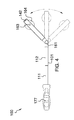
- FIG. 1 is a perspective view of an embodiment of the disclosure.
- FIG. 2 is a bottom view of an embodiment of the disclosure.
- FIG. 3 is a front view of an embodiment of the disclosure.
- FIG. 4 is a side view of an embodiment of the disclosure.
- FIG. 5 is an in use view of an embodiment of the disclosure.
- FIG. 6 is a detail view of an embodiment of the disclosure.
- FIG. 7 is a detail view of an embodiment of the disclosure.
- FIGS. 1 through 7 Detailed reference will now be made to one or more potential embodiments of the disclosure, which are illustrated in FIGS. 1 through 7 .
- the massaging device 100 (hereinafter invention) comprises a telescopic handle 101 , a threaded connection 102 , and a plurality of heads 103 .
- the threaded connection 102 attaches a head selected from the plurality of heads 103 to the telescopic handle 101 .
- the invention 100 is adapted for use with a body 171 of a person.
- the invention 100 is adapted for use in physical therapy.
- the invention 100 is a device that allows the person to massage portions of the body 171 that are otherwise difficult to reach.
- Each of the plurality of heads 103 further comprises a massaging surface 164 .
- the differences between each of the plurality of heads 103 is defined by differences in the massaging surface 164 .
- Each of the plurality of heads 103 of invention 100 pivots allowing the angle of the massaging surface 164 to be changed relative to the body 171 of the person.
- Each of the plurality of heads 103 is interchangeable.
- the threaded connection 102 comprises an interior screw thread 121 and an exterior screw thread 122 .
- the interior screw thread 121 is formed into each head selected from the plurality of heads 103 .
- the exterior screw thread 122 is formed on the telescopic handle 101 .
- the exterior screw thread 122 and the interior screw thread 121 are designed to work with each other. To join the telescopic handle 101 to the selected head, the exterior screw thread 122 screws into the interior screw thread 121 .
- the telescopic handle 101 comprises a first shaft 111 , a second shaft 112 , and a detent 113 .
- the first shaft 111 is further defined with a first end 151 and a second end 152 .
- the second shaft 112 is further defined with a third end 153 and a fourth end 154 .
- the detent 113 attaches the first shaft 111 to the second shaft 112 .
- the telescopic handle 101 is further defined with an ergonomic handle 177 that is adjacent to the first end 151 .
- the ergonomic handle 177 is adapted to be manually grasped via a hand 178 .
- the first shaft 111 is a readily and commercially available pipe.
- the second shaft 112 is a readily and commercially available pipe.
- the outer diameter of the first shaft 111 is lesser than the inner diameter of the second shaft 112 such that the second end 152 of the first shaft 111 will slide into the third end 153 of the second shaft 112 in a telescopic fashion.
- the relative position of the second end 152 of the first shaft 111 within the second shaft 112 is changed.
- the relative position of the second end 152 of the first shaft 111 within the second shaft 112 is locked into position using the detent 113 .
- the detent 113 is a commercially available device that is designed to lock telescopic structures in a fixed relative position. These devices are well known in the mechanical arts. Suitable locking devices for use as the detent 113 include, but are not limited to, a threaded clutch, a split collar, a G snap collar, or a set knob.
- each of the plurality of heads 103 comprises a locking pivot 161 , a Y base 162 , an axle 163 and the massaging surface 164 .
- the axle 163 attaches the massaging surface 164 to the Y base 162 .
- the locking pivot 161 attaches the Y base 162 to the telescopic handle 101 .
- the axle 163 is further defined with a ninth end 159 and a tenth end 160 .
- the Y base 162 comprises a first arm 141 , a second arm 142 , a leg 143 , and a hood 144 .
- the leg 143 is further defined with a seventh end 157 and an eighth end 158 .
- the first arm 141 and the second arm 142 both project away from the eighth end 158 of leg 143 to form the characteristic Y shape of a slingshot.
- the hood 144 comprises a first plate 145 and a second plate 146 that are attached to the leg 143 and project beyond the seventh end 157 of the leg 143 towards the stub 133 . The use of the hood 144 is described elsewhere in this disclosure.
- the locking pivot 161 comprises a pivot shaft 131 , a locking mechanism 132 , and a stub 133 .
- the stub 133 is further defined with a fifth end 155 and a sixth end 156 .
- the stub 133 attaches to the telescopic handle 101 .
- the pivot shaft 131 attaches the stub 133 to the hood 144 .
- the locking mechanism 132 is a device that prevents the rotation of the hood 144 relative to the stub 133 .
- the locking mechanism 132 is a set screw 134 .
- the interior screw thread 121 is formed in the fifth end 155 of the stub 133 .
- the hood 144 is placed around the sixth end 156 of the stub 133 and is attached to the sixth end 156 of the stub 133 using the pivot shaft 131 .
- Methods to attach hoods to shafts using a pivot shaft 131 are well known and documented in the mechanical arts.
- the locking mechanism 132 is a set screw 134 that is inserted through the side of the first plate 145 into the face of the stub 133 .
- Each massaging surface 164 is a structure that is designed to provide therapeutic pressure to or therapeutic kneading on the body 171 .
- Each massaging surface 164 is formed with an axle hole 165 .
- the purpose of the axle hole 165 is to receive the axle 163 such that the axle 163 will attach the massaging surface 164 to the Y base 162 .
- the axle hole 165 is sized such that the massaging surface 164 will rotate such that the axle 163 forms the axis of rotation of the massaging surface 164 .
- the ninth end 159 of the axle 163 is attached to the first arm 141 .
- the tenth end 160 of the axle 163 is attached to the second arm 142 .
- the plurality of heads 103 comprises three heads which are differentiated by: 1) the use of a smooth ball 181 as a first massaging surface, 2) the use of a knobbed 182 surface as a second massaging surface; and, 3) the use of a pinwheel 183 surface as a third massaging surface.
- the knobbed 182 surface is a spherical surface that further comprises a plurality of knobs.
- the pinwheel 183 surface comprises a plurality of blades that rotate around the axis.
- a head is selected from the plurality of heads 103 and is attached to the telescopic handle 101 using the threaded connection 102 as described elsewhere in this disclosure.
- the length of the telescopic handle 101 is adjusted by adjusting the relative position of the second end 152 within the second shaft 112 as described elsewhere in this disclosure.
- the relative angle of the Y base 162 to the telescopic handle 101 is adjusted as described elsewhere in this disclosure.
- the person then uses the telescopic handle 101 to press the massaging surface 164 of the selected head in a therapeutic fashion against the body 171 .
- the massaging surfaces 164 are formed from polyurethane. However, it shall be noted that the massaging surface 164 may be a tennis ball.
- the balance of the invention 100 is formed from molded plastic. Suitable plastics include, but are not limited to, polyethylene, polyvinylchloride, polypropylene, or polycarbonate.
- a second potential embodiment of the disclosure is identical to the first potential embodiment of the disclosure except that the balance of the invention 100 is formed from aluminum.
- an axle is a cylindrical shaft that is inserted through the center of an object such that the object can rotate using the axle as an axis of rotation.
- a ball refers to an object with a spherical or nearly spherical shape.
- center of rotation is the point of a rotating plane that does not move with the rotation of the plane.
- a line within a rotating three dimensional object that does not move with the rotation of the object is referred to as an axis of rotation.
- a detent is a device for positioning and holding one mechanical part in relation to another in a manner such that the device can be released by force applied to one or more of the parts.
- Exterior Screw Thread An exterior screw thread is a ridge wrapped around the outer surface of a tube in the form of a helical structure that is used to convert rotational movement into linear movement.
- a handle is an object by which a tool, object, or door is held or manipulated with the hand.
- Inner Diameter As used in this disclosure, the term inner diameter is used in the same way that a plumber would refer to the inner diameter of a pipe.
- An interior screw thread is a groove that is formed around the inner surface of a tube in the form of a helical structure that is used to convert rotational movement into linear movement.
- Outer Diameter As used in this disclosure, the term outer diameter is used in the same way that a plumber would refer to the outer diameter of a pipe.
- Pipe As used in this disclosure, the term pipe is used to describe a rigid hollow cylinder. While pipes that are suitable for use in this disclosure are often used to transport or conveys fluids or gasses, the purpose of the pipes in this disclosure are structural. In this disclosure, the terms inner diameter of a pipe and outer diameter are used as they would be used by those skilled in the plumbing arts.
- Pivot As used in this disclosure, a pivot is a rod or shaft around which an object rotates or swings.
- shaft As used in this disclosure, the term shaft is used to describe a rigid cylinder that is often used as the handle of a tool or implement. The terms inner diameter of the shaft and outer diameter of the shaft are used as they would be used by those skilled in the plumbing arts. The definition of shaft explicitly includes solid shafts or shafts that are formed more like pipes with a hollow passage through the shaft that runs along the center axis of the shaft cylinder.
- Telescopic As used in this disclosure, telescopic is an adjective that describes an object made of sections that fit or slide into each other such that the object can be made longer or shorter by adjusting the relative positions of the sections.
- a threaded connection is a type of fastener that is used to join a first tube shaped and a second tube shaped object together.
- the first tube shaped object is fitted with fitted with a first fitting selected from an interior screw thread or an exterior screw thread.
- the second tube shaped object is fitted with the remaining screw thread.
- the tube shaped object fitted with the exterior screw thread is placed into the remaining tube shaped object such that: 1) the interior screw thread and the exterior screw thread interconnect; and, 2) when the tube shaped object fitted with the exterior screw thread is rotated the rotational motion is converted into linear motion that moves the tube shaped object fitted with the exterior screw thread either into or out of the remaining tube shaped object.
- the direction of linear motion is determined by the direction of rotation.
Landscapes
- Health & Medical Sciences (AREA)
- Epidemiology (AREA)
- Pain & Pain Management (AREA)
- Physical Education & Sports Medicine (AREA)
- Rehabilitation Therapy (AREA)
- Life Sciences & Earth Sciences (AREA)
- Animal Behavior & Ethology (AREA)
- General Health & Medical Sciences (AREA)
- Public Health (AREA)
- Veterinary Medicine (AREA)
- Massaging Devices (AREA)
Abstract
Description
Claims (9)
Priority Applications (1)
| Application Number | Priority Date | Filing Date | Title |
|---|---|---|---|
| US15/340,630 US10327981B1 (en) | 2016-11-01 | 2016-11-01 | Massaging device |
Applications Claiming Priority (1)
| Application Number | Priority Date | Filing Date | Title |
|---|---|---|---|
| US15/340,630 US10327981B1 (en) | 2016-11-01 | 2016-11-01 | Massaging device |
Publications (1)
| Publication Number | Publication Date |
|---|---|
| US10327981B1 true US10327981B1 (en) | 2019-06-25 |
Family
ID=66996666
Family Applications (1)
| Application Number | Title | Priority Date | Filing Date |
|---|---|---|---|
| US15/340,630 Active 2037-10-26 US10327981B1 (en) | 2016-11-01 | 2016-11-01 | Massaging device |
Country Status (1)
| Country | Link |
|---|---|
| US (1) | US10327981B1 (en) |
Cited By (22)
| Publication number | Priority date | Publication date | Assignee | Title |
|---|---|---|---|---|
| US20180161234A1 (en) * | 2016-12-12 | 2018-06-14 | Firstborn Designs, LLC | Telescopic Hand-Held Massager |
| US20190110583A1 (en) * | 2017-10-18 | 2019-04-18 | The Boulevard Group, LLC | Back-invigorator brush, roller and loofa |
| US20200085675A1 (en) * | 2018-09-18 | 2020-03-19 | Pado, Inc. | Versatile and Ergonomic Percussion Massage Appliance |
| US20210369549A1 (en) * | 2020-06-01 | 2021-12-02 | Thomas Almodovar | Adjustable massage device for trigger point release |
| WO2022050962A1 (en) * | 2020-09-04 | 2022-03-10 | Hillary Hayman | Body-specific derma roller |
| US20220096315A1 (en) * | 2020-10-23 | 2022-03-31 | Hillary Hayman | Uni-inner stabilizer configuration for derma roller apparatus |
| US11311454B2 (en) * | 2019-03-28 | 2022-04-26 | Softwave Tissue Regeneration Technologies, Llc | Handheld acoustic shock wave or pressure pulse application device and methods of use |
| US20220125669A1 (en) * | 2020-10-23 | 2022-04-28 | Hillary Hayman | Micro-outer stabilizer configuration for derma roller apparatus |
| USD954960S1 (en) * | 2020-03-10 | 2022-06-14 | Masafumi Yamasaki | Attachment for chiropractic device |
| US11376185B2 (en) * | 2017-10-06 | 2022-07-05 | 3Rd Wheel Productions Pty Ltd | Massage apparatus and method of use |
| EP4137112A1 (en) * | 2021-08-20 | 2023-02-22 | Ningbo Juyang Electronic Commerce Co., Ltd. | Body shaping stick |
| US11607365B2 (en) * | 2016-12-26 | 2023-03-21 | Mtg Co., Ltd. | Beauty device |
| USD992138S1 (en) | 2021-11-10 | 2023-07-11 | Pado, Inc. | Massager |
| USD992137S1 (en) | 2021-09-08 | 2023-07-11 | Pado, Inc. | Massager attachment |
| USD1007697S1 (en) * | 2022-06-10 | 2023-12-12 | Sichuan Qianli-beoka Medical Technology Inc. | Massage head of the fascia gun |
| US11872177B1 (en) * | 2019-09-12 | 2024-01-16 | Gary Graham | Mounted massage roller |
| USD1013279S1 (en) | 2022-06-17 | 2024-01-30 | Abraham Menasche | Foot file |
| WO2024022083A1 (en) * | 2022-07-26 | 2024-02-01 | 方志向 | Massage device |
| USD1020102S1 (en) | 2022-06-30 | 2024-03-26 | Abraham Menasche | Foot file |
| US11963920B2 (en) | 2018-08-29 | 2024-04-23 | Pado, Inc. | Massage appliance having floating motor and vibration plate for vibration isolation |
| US20240277549A1 (en) * | 2022-03-01 | 2024-08-22 | Medi-Dyne Healthcare Products, Ltd. | Adjustable, multi-functional shoulder stretching device |
| USD1089850S1 (en) | 2023-06-12 | 2025-08-19 | Abraham Menasche | Foot file |
Citations (46)
| Publication number | Priority date | Publication date | Assignee | Title |
|---|---|---|---|---|
| US693064A (en) | 1901-06-21 | 1902-02-11 | Charles I Proben | Massage device. |
| US1011498A (en) * | 1910-11-01 | 1911-12-12 | Arthem I Saphiloff | Skin-cleanser. |
| GB205989A (en) | 1922-10-13 | 1923-11-01 | Eunice Kate Saville | Improvements in massaging appliances |
| US1958936A (en) * | 1932-04-05 | 1934-05-15 | Bajette Richard | Electric vibrator massage device |
| US2168975A (en) * | 1937-06-04 | 1939-08-08 | Clarke Dumont | Massaging device |
| US2246263A (en) * | 1940-03-19 | 1941-06-17 | Ralph J Patterson | Handle for hand implements |
| US2347327A (en) * | 1941-11-18 | 1944-04-25 | Bessie P London | Massaging apparatus |
| US3856002A (en) * | 1973-08-28 | 1974-12-24 | Raymond Lee Organization Inc | Massage device |
| US4210135A (en) * | 1977-08-24 | 1980-07-01 | Erich Deuser | Massaging device |
| USD349576S (en) * | 1993-05-26 | 1994-08-09 | Sunbeam Corporation | Massager |
| US5360111A (en) * | 1993-09-02 | 1994-11-01 | Arispe Steven E | Compact lotion applicator |
| USD363783S (en) * | 1994-09-06 | 1995-10-31 | Malis William G | Folding hand-held accupressure massager |
| US5566418A (en) * | 1995-10-05 | 1996-10-22 | Steffen; David H. | Back hand |
| US5664281A (en) * | 1996-02-27 | 1997-09-09 | Pelfrey; Diana L. | Suntan lotion applicator |
| US5671497A (en) * | 1995-06-23 | 1997-09-30 | Abdo; Joel M. | Applicator for applying lotion to hard-to-reach areas of body |
| US5779291A (en) * | 1995-11-17 | 1998-07-14 | Forest; Robert | Aquarium tool |
| USD415569S (en) | 1998-06-05 | 1999-10-19 | Wyrwa Lester J | Massager |
| US6176841B1 (en) * | 1999-08-31 | 2001-01-23 | Wang Kuo Tso | Facial massager |
| US6245031B1 (en) | 1997-12-29 | 2001-06-12 | Roger C. Pearson | Massage system |
| US6415470B1 (en) * | 2000-10-20 | 2002-07-09 | Benedict L. Ramrattan | Lotion applicator |
| US20030009116A1 (en) * | 2001-07-03 | 2003-01-09 | Luettgen Harold A. | Vibrating personal massager |
| US20040215115A1 (en) * | 2003-04-28 | 2004-10-28 | Jiann-Chern Sheen | Folding collapsible massaging bar |
| US6830552B1 (en) * | 2003-04-29 | 2004-12-14 | Mark Antonio Gonzalez | Backscratcher with a telescopically adjustable shaft and with a plurality of screw-on attachment end pieces |
| US6988997B2 (en) | 2003-06-06 | 2006-01-24 | Stultz Michael O | Back massager with interchangeable contact heads |
| US6994680B1 (en) * | 2004-07-14 | 2006-02-07 | Gina Aponte | Automated back and belly scratcher |
| US20060069333A1 (en) * | 2002-12-03 | 2006-03-30 | Pidcock Ralph M | Method and apparatus for relieving leg cramps and massaging muscles |
| US20060142679A1 (en) * | 2004-12-25 | 2006-06-29 | Fu-Hsing Tan | Backscratcher for relieving itches |
| US7169120B2 (en) * | 2004-05-11 | 2007-01-30 | Murdock Matthew L | Device and method for providing a massage |
| US20070083135A1 (en) * | 2005-10-12 | 2007-04-12 | L'oreal | Massage device having deformable and/or movable branches and massage method using same |
| US7309180B2 (en) | 2004-03-12 | 2007-12-18 | Syrenthia Russell | Multipurpose hygienic implement |
| US7337933B1 (en) * | 2006-08-30 | 2008-03-04 | Valeriy Klinberg | Pocket shoe horn with telescopic handle |
| US20090093743A1 (en) * | 2007-10-09 | 2009-04-09 | Corzine Jean P | Versatile back treatment implement system |
| US20090177126A1 (en) * | 2005-12-23 | 2009-07-09 | Marc Berger | Muscle Stimulation Device |
| US7698773B2 (en) | 2007-08-14 | 2010-04-20 | Helen Sotelo | Holder for hygienic wipes and the like |
| US20110224588A1 (en) * | 2007-11-20 | 2011-09-15 | Rene Grippo | Personel Massaging System |
| US20130023807A1 (en) * | 2011-07-21 | 2013-01-24 | Hennessey Daniel J | Massager |
| US20150245977A1 (en) * | 2014-02-28 | 2015-09-03 | Arno Sarkis Sungarian | Rehabilitation device |
| US20150374576A1 (en) * | 2011-09-08 | 2015-12-31 | Gideon Dagan | Self-Massage Device |
| US20160136032A1 (en) * | 2014-11-14 | 2016-05-19 | Tara Dakides | Therapeutic massage device |
| US20160151235A1 (en) * | 2014-12-02 | 2016-06-02 | Hsien-Wen Yu | Massage device |
| US20160166462A1 (en) * | 2014-12-10 | 2016-06-16 | Richard V. Conder | Personal massage apparatus |
| US20160213554A1 (en) * | 2014-11-05 | 2016-07-28 | Sean Possemato | Massaging Device |
| US20160271006A1 (en) * | 2014-06-11 | 2016-09-22 | Nicholas Jennings McGrue | Handheld manual massage device |
| US9532918B1 (en) * | 2012-09-19 | 2017-01-03 | John G Louis | Handheld massage device |
| US20170156969A1 (en) * | 2015-12-04 | 2017-06-08 | John Fitzsimmons | Foot Massaging Assembly |
| US20180042806A1 (en) * | 2016-08-09 | 2018-02-15 | Nicholas Thomas West | Muscle Roller |
-
2016
- 2016-11-01 US US15/340,630 patent/US10327981B1/en active Active
Patent Citations (46)
| Publication number | Priority date | Publication date | Assignee | Title |
|---|---|---|---|---|
| US693064A (en) | 1901-06-21 | 1902-02-11 | Charles I Proben | Massage device. |
| US1011498A (en) * | 1910-11-01 | 1911-12-12 | Arthem I Saphiloff | Skin-cleanser. |
| GB205989A (en) | 1922-10-13 | 1923-11-01 | Eunice Kate Saville | Improvements in massaging appliances |
| US1958936A (en) * | 1932-04-05 | 1934-05-15 | Bajette Richard | Electric vibrator massage device |
| US2168975A (en) * | 1937-06-04 | 1939-08-08 | Clarke Dumont | Massaging device |
| US2246263A (en) * | 1940-03-19 | 1941-06-17 | Ralph J Patterson | Handle for hand implements |
| US2347327A (en) * | 1941-11-18 | 1944-04-25 | Bessie P London | Massaging apparatus |
| US3856002A (en) * | 1973-08-28 | 1974-12-24 | Raymond Lee Organization Inc | Massage device |
| US4210135A (en) * | 1977-08-24 | 1980-07-01 | Erich Deuser | Massaging device |
| USD349576S (en) * | 1993-05-26 | 1994-08-09 | Sunbeam Corporation | Massager |
| US5360111A (en) * | 1993-09-02 | 1994-11-01 | Arispe Steven E | Compact lotion applicator |
| USD363783S (en) * | 1994-09-06 | 1995-10-31 | Malis William G | Folding hand-held accupressure massager |
| US5671497A (en) * | 1995-06-23 | 1997-09-30 | Abdo; Joel M. | Applicator for applying lotion to hard-to-reach areas of body |
| US5566418A (en) * | 1995-10-05 | 1996-10-22 | Steffen; David H. | Back hand |
| US5779291A (en) * | 1995-11-17 | 1998-07-14 | Forest; Robert | Aquarium tool |
| US5664281A (en) * | 1996-02-27 | 1997-09-09 | Pelfrey; Diana L. | Suntan lotion applicator |
| US6245031B1 (en) | 1997-12-29 | 2001-06-12 | Roger C. Pearson | Massage system |
| USD415569S (en) | 1998-06-05 | 1999-10-19 | Wyrwa Lester J | Massager |
| US6176841B1 (en) * | 1999-08-31 | 2001-01-23 | Wang Kuo Tso | Facial massager |
| US6415470B1 (en) * | 2000-10-20 | 2002-07-09 | Benedict L. Ramrattan | Lotion applicator |
| US20030009116A1 (en) * | 2001-07-03 | 2003-01-09 | Luettgen Harold A. | Vibrating personal massager |
| US20060069333A1 (en) * | 2002-12-03 | 2006-03-30 | Pidcock Ralph M | Method and apparatus for relieving leg cramps and massaging muscles |
| US20040215115A1 (en) * | 2003-04-28 | 2004-10-28 | Jiann-Chern Sheen | Folding collapsible massaging bar |
| US6830552B1 (en) * | 2003-04-29 | 2004-12-14 | Mark Antonio Gonzalez | Backscratcher with a telescopically adjustable shaft and with a plurality of screw-on attachment end pieces |
| US6988997B2 (en) | 2003-06-06 | 2006-01-24 | Stultz Michael O | Back massager with interchangeable contact heads |
| US7309180B2 (en) | 2004-03-12 | 2007-12-18 | Syrenthia Russell | Multipurpose hygienic implement |
| US7169120B2 (en) * | 2004-05-11 | 2007-01-30 | Murdock Matthew L | Device and method for providing a massage |
| US6994680B1 (en) * | 2004-07-14 | 2006-02-07 | Gina Aponte | Automated back and belly scratcher |
| US20060142679A1 (en) * | 2004-12-25 | 2006-06-29 | Fu-Hsing Tan | Backscratcher for relieving itches |
| US20070083135A1 (en) * | 2005-10-12 | 2007-04-12 | L'oreal | Massage device having deformable and/or movable branches and massage method using same |
| US20090177126A1 (en) * | 2005-12-23 | 2009-07-09 | Marc Berger | Muscle Stimulation Device |
| US7337933B1 (en) * | 2006-08-30 | 2008-03-04 | Valeriy Klinberg | Pocket shoe horn with telescopic handle |
| US7698773B2 (en) | 2007-08-14 | 2010-04-20 | Helen Sotelo | Holder for hygienic wipes and the like |
| US20090093743A1 (en) * | 2007-10-09 | 2009-04-09 | Corzine Jean P | Versatile back treatment implement system |
| US20110224588A1 (en) * | 2007-11-20 | 2011-09-15 | Rene Grippo | Personel Massaging System |
| US20130023807A1 (en) * | 2011-07-21 | 2013-01-24 | Hennessey Daniel J | Massager |
| US20150374576A1 (en) * | 2011-09-08 | 2015-12-31 | Gideon Dagan | Self-Massage Device |
| US9532918B1 (en) * | 2012-09-19 | 2017-01-03 | John G Louis | Handheld massage device |
| US20150245977A1 (en) * | 2014-02-28 | 2015-09-03 | Arno Sarkis Sungarian | Rehabilitation device |
| US20160271006A1 (en) * | 2014-06-11 | 2016-09-22 | Nicholas Jennings McGrue | Handheld manual massage device |
| US20160213554A1 (en) * | 2014-11-05 | 2016-07-28 | Sean Possemato | Massaging Device |
| US20160136032A1 (en) * | 2014-11-14 | 2016-05-19 | Tara Dakides | Therapeutic massage device |
| US20160151235A1 (en) * | 2014-12-02 | 2016-06-02 | Hsien-Wen Yu | Massage device |
| US20160166462A1 (en) * | 2014-12-10 | 2016-06-16 | Richard V. Conder | Personal massage apparatus |
| US20170156969A1 (en) * | 2015-12-04 | 2017-06-08 | John Fitzsimmons | Foot Massaging Assembly |
| US20180042806A1 (en) * | 2016-08-09 | 2018-02-15 | Nicholas Thomas West | Muscle Roller |
Cited By (25)
| Publication number | Priority date | Publication date | Assignee | Title |
|---|---|---|---|---|
| US20180161234A1 (en) * | 2016-12-12 | 2018-06-14 | Firstborn Designs, LLC | Telescopic Hand-Held Massager |
| US11607365B2 (en) * | 2016-12-26 | 2023-03-21 | Mtg Co., Ltd. | Beauty device |
| US11376185B2 (en) * | 2017-10-06 | 2022-07-05 | 3Rd Wheel Productions Pty Ltd | Massage apparatus and method of use |
| US20190110583A1 (en) * | 2017-10-18 | 2019-04-18 | The Boulevard Group, LLC | Back-invigorator brush, roller and loofa |
| US11963920B2 (en) | 2018-08-29 | 2024-04-23 | Pado, Inc. | Massage appliance having floating motor and vibration plate for vibration isolation |
| US10959908B2 (en) * | 2018-09-18 | 2021-03-30 | Pado, Inc. | Versatile and ergonomic percussion massage appliance |
| US20200085675A1 (en) * | 2018-09-18 | 2020-03-19 | Pado, Inc. | Versatile and Ergonomic Percussion Massage Appliance |
| US11311454B2 (en) * | 2019-03-28 | 2022-04-26 | Softwave Tissue Regeneration Technologies, Llc | Handheld acoustic shock wave or pressure pulse application device and methods of use |
| US11844739B2 (en) | 2019-03-28 | 2023-12-19 | Softwave Tissue Regeneration Technologies, Llc | Handheld acoustic shock wave or pressure pulse application device and methods of use |
| US11872177B1 (en) * | 2019-09-12 | 2024-01-16 | Gary Graham | Mounted massage roller |
| USD954960S1 (en) * | 2020-03-10 | 2022-06-14 | Masafumi Yamasaki | Attachment for chiropractic device |
| US20210369549A1 (en) * | 2020-06-01 | 2021-12-02 | Thomas Almodovar | Adjustable massage device for trigger point release |
| US11938076B2 (en) * | 2020-06-01 | 2024-03-26 | Thomas Almodovar | Adjustable massage device for trigger point release |
| WO2022050962A1 (en) * | 2020-09-04 | 2022-03-10 | Hillary Hayman | Body-specific derma roller |
| US20220096315A1 (en) * | 2020-10-23 | 2022-03-31 | Hillary Hayman | Uni-inner stabilizer configuration for derma roller apparatus |
| US20220125669A1 (en) * | 2020-10-23 | 2022-04-28 | Hillary Hayman | Micro-outer stabilizer configuration for derma roller apparatus |
| EP4137112A1 (en) * | 2021-08-20 | 2023-02-22 | Ningbo Juyang Electronic Commerce Co., Ltd. | Body shaping stick |
| USD992137S1 (en) | 2021-09-08 | 2023-07-11 | Pado, Inc. | Massager attachment |
| USD992138S1 (en) | 2021-11-10 | 2023-07-11 | Pado, Inc. | Massager |
| US20240277549A1 (en) * | 2022-03-01 | 2024-08-22 | Medi-Dyne Healthcare Products, Ltd. | Adjustable, multi-functional shoulder stretching device |
| USD1007697S1 (en) * | 2022-06-10 | 2023-12-12 | Sichuan Qianli-beoka Medical Technology Inc. | Massage head of the fascia gun |
| USD1013279S1 (en) | 2022-06-17 | 2024-01-30 | Abraham Menasche | Foot file |
| USD1020102S1 (en) | 2022-06-30 | 2024-03-26 | Abraham Menasche | Foot file |
| WO2024022083A1 (en) * | 2022-07-26 | 2024-02-01 | 方志向 | Massage device |
| USD1089850S1 (en) | 2023-06-12 | 2025-08-19 | Abraham Menasche | Foot file |
Similar Documents
| Publication | Publication Date | Title |
|---|---|---|
| US10327981B1 (en) | Massaging device | |
| US10335628B1 (en) | Rolling dumbells | |
| US20180161234A1 (en) | Telescopic Hand-Held Massager | |
| US9706843B2 (en) | Display support device having a tightening unit | |
| WO2012158865A3 (en) | Telescoping im nail and actuating mechanism | |
| WO2011116158A3 (en) | Telescoping im nail and actuating mechanism | |
| US5046974A (en) | Ancillary filler for steerable outboard motor | |
| US7621023B2 (en) | Adjustable tool handle | |
| US20200113152A1 (en) | Pet Treat Holder with Adjustable Opening for Gripping Chew Treats or Releasing Kibble Treats | |
| US20080069694A1 (en) | Electric fan | |
| JP2016515013A (en) | Sports equipment with a rotatable handle | |
| EP4275646A3 (en) | Ultrasonic surgical instrument with transducer locking feature | |
| US2840402A (en) | Telescopic lock | |
| US9441353B1 (en) | Reinforced toilet plunger and case | |
| US10577181B1 (en) | Adjustable diameter pipe grabber | |
| US7398954B2 (en) | Remote-coupled faucet adapter | |
| US10252349B2 (en) | Forward grip system | |
| USD773569S1 (en) | Exercise device with ergonomic hand grip balls | |
| CN110730704A (en) | Power wrench with angle transmission | |
| US20200282281A1 (en) | Wrist Rehabilitation Aid System | |
| TWM483149U (en) | Ratchet wrench for single-hand operation and direction switching | |
| US10327600B1 (en) | Personal hygiene and wiping tool | |
| US9651041B2 (en) | Operating handle assembly for hand air pump | |
| WO2016059538A4 (en) | Variable suction control | |
| CN108938317B (en) | Finger rehabilitation device |
Legal Events
| Date | Code | Title | Description |
|---|---|---|---|
| FEPP | Fee payment procedure |
Free format text: ENTITY STATUS SET TO MICRO (ORIGINAL EVENT CODE: MICR); ENTITY STATUS OF PATENT OWNER: MICROENTITY |
|
| STCF | Information on status: patent grant |
Free format text: PATENTED CASE |
|
| FEPP | Fee payment procedure |
Free format text: MAINTENANCE FEE REMINDER MAILED (ORIGINAL EVENT CODE: REM.); ENTITY STATUS OF PATENT OWNER: MICROENTITY |
|
| FEPP | Fee payment procedure |
Free format text: SURCHARGE FOR LATE PAYMENT, MICRO ENTITY (ORIGINAL EVENT CODE: M3554); ENTITY STATUS OF PATENT OWNER: MICROENTITY |
|
| MAFP | Maintenance fee payment |
Free format text: PAYMENT OF MAINTENANCE FEE, 4TH YEAR, MICRO ENTITY (ORIGINAL EVENT CODE: M3551); ENTITY STATUS OF PATENT OWNER: MICROENTITY Year of fee payment: 4 |