US10323830B2 - Bulb gripper for holding decorative lights - Google Patents
Bulb gripper for holding decorative lights Download PDFInfo
- Publication number
- US10323830B2 US10323830B2 US15/856,627 US201715856627A US10323830B2 US 10323830 B2 US10323830 B2 US 10323830B2 US 201715856627 A US201715856627 A US 201715856627A US 10323830 B2 US10323830 B2 US 10323830B2
- Authority
- US
- United States
- Prior art keywords
- arm
- projections
- bulb
- gripper
- decorative light
- Prior art date
- Legal status (The legal status is an assumption and is not a legal conclusion. Google has not performed a legal analysis and makes no representation as to the accuracy of the status listed.)
- Active
Links
Images


Classifications
-
- F—MECHANICAL ENGINEERING; LIGHTING; HEATING; WEAPONS; BLASTING
- F21—LIGHTING
- F21V—FUNCTIONAL FEATURES OR DETAILS OF LIGHTING DEVICES OR SYSTEMS THEREOF; STRUCTURAL COMBINATIONS OF LIGHTING DEVICES WITH OTHER ARTICLES, NOT OTHERWISE PROVIDED FOR
- F21V17/00—Fastening of component parts of lighting devices, e.g. shades, globes, refractors, reflectors, filters, screens, grids or protective cages
- F21V17/10—Fastening of component parts of lighting devices, e.g. shades, globes, refractors, reflectors, filters, screens, grids or protective cages characterised by specific fastening means or way of fastening
- F21V17/16—Fastening of component parts of lighting devices, e.g. shades, globes, refractors, reflectors, filters, screens, grids or protective cages characterised by specific fastening means or way of fastening by deformation of parts; Snap action mounting
-
- F—MECHANICAL ENGINEERING; LIGHTING; HEATING; WEAPONS; BLASTING
- F21—LIGHTING
- F21S—NON-PORTABLE LIGHTING DEVICES; SYSTEMS THEREOF; VEHICLE LIGHTING DEVICES SPECIALLY ADAPTED FOR VEHICLE EXTERIORS
- F21S4/00—Lighting devices or systems using a string or strip of light sources
- F21S4/10—Lighting devices or systems using a string or strip of light sources with light sources attached to loose electric cables, e.g. Christmas tree lights
-
- F—MECHANICAL ENGINEERING; LIGHTING; HEATING; WEAPONS; BLASTING
- F21—LIGHTING
- F21V—FUNCTIONAL FEATURES OR DETAILS OF LIGHTING DEVICES OR SYSTEMS THEREOF; STRUCTURAL COMBINATIONS OF LIGHTING DEVICES WITH OTHER ARTICLES, NOT OTHERWISE PROVIDED FOR
- F21V17/00—Fastening of component parts of lighting devices, e.g. shades, globes, refractors, reflectors, filters, screens, grids or protective cages
- F21V17/02—Fastening of component parts of lighting devices, e.g. shades, globes, refractors, reflectors, filters, screens, grids or protective cages with provision for adjustment
-
- F—MECHANICAL ENGINEERING; LIGHTING; HEATING; WEAPONS; BLASTING
- F21—LIGHTING
- F21V—FUNCTIONAL FEATURES OR DETAILS OF LIGHTING DEVICES OR SYSTEMS THEREOF; STRUCTURAL COMBINATIONS OF LIGHTING DEVICES WITH OTHER ARTICLES, NOT OTHERWISE PROVIDED FOR
- F21V21/00—Supporting, suspending, or attaching arrangements for lighting devices; Hand grips
- F21V21/08—Devices for easy attachment to any desired place, e.g. clip, clamp, magnet
- F21V21/0824—Ground spikes
-
- F—MECHANICAL ENGINEERING; LIGHTING; HEATING; WEAPONS; BLASTING
- F21—LIGHTING
- F21V—FUNCTIONAL FEATURES OR DETAILS OF LIGHTING DEVICES OR SYSTEMS THEREOF; STRUCTURAL COMBINATIONS OF LIGHTING DEVICES WITH OTHER ARTICLES, NOT OTHERWISE PROVIDED FOR
- F21V21/00—Supporting, suspending, or attaching arrangements for lighting devices; Hand grips
- F21V21/08—Devices for easy attachment to any desired place, e.g. clip, clamp, magnet
- F21V21/088—Clips; Clamps
-
- F—MECHANICAL ENGINEERING; LIGHTING; HEATING; WEAPONS; BLASTING
- F21—LIGHTING
- F21W—INDEXING SCHEME ASSOCIATED WITH SUBCLASSES F21K, F21L, F21S and F21V, RELATING TO USES OR APPLICATIONS OF LIGHTING DEVICES OR SYSTEMS
- F21W2121/00—Use or application of lighting devices or systems for decorative purposes, not provided for in codes F21W2102/00 – F21W2107/00
- F21W2121/004—Use or application of lighting devices or systems for decorative purposes, not provided for in codes F21W2102/00 – F21W2107/00 mounted on the exterior of houses or other buildings to illuminate parts thereof
Definitions
- This invention relates to clips and stakes for displaying decorative lights.
- Decorative lights typically consist of a large number of light sockets being wired together with light bulbs positioned in the light sockets.
- the string of lights is then attached to the face of a building, mounted on stakes, wrapped around a tree or hung on a seasonal display.
- Strings of lights have been mounted by retaining either the light socket or the wire.
- the object of these holders is to display the lights so that they can easily be seen.
- the holders must not be adversely affected by cold temperatures and should be able to hold the lights during high winds which commonly accompany winter storms.
- LED lights have become available that differ somewhat in size from their incandescent counterpart and created new sizes called C4, C5, C6, C12 and G28.
- the socket can also vary in size depending upon the manufacturer.
- a decorative light holder should be capable of holding all these sizes of light bulbs.
- U.S. Pat. No. 5,667,174 discloses a stake having a light holder for holding decorative lights.
- the light holder has an S-shaped bulb gripper portion.
- One end of the bulb gripper has a small opening for holding a mini-light and the other end has a larger opening for holding a C7 or a C9 light.
- the bulb gripper is made of a resilient material so that the distal end and the proximate end can be sufficiently spread apart to receive a decorative light socket and then close to grasp the socket.
- U.S. Pat. No. 5,669,709 discloses a decorative light holder having an S-shaped bulb gripper that can be attached to a gutter or shingles.
- one half of the S-shape is sized to hold a mini-light socket and the other half is larger and sized to hold the standard C7 and outdoor C9 sockets.
- U.S. Pat. No. Des. 331,360 discloses a hook for supporting Christmas lights adjacent roofing shingles.
- This hook is comprised of a small stake which fits between the shingles having a single spiral at one end. The spiral end is sized to hold the wire of the Christmas light string, not a bulb or socket.
- Similar devices comprised of a stake or straight pin with a curved holder attached at one end have been used to retain other structures or products.
- Another prior art device provides an L-shaped light support bracket with one of the legs being fitted under a shingle.
- the other leg includes a hole sized to receive a light bulb.
- This type of light support bracket can also be positioned within a retaining strip which is permanently attached to a flat building surface. Examples of these light mountings are shown in U.S. Pat. Nos. 4,905,131; 4,901,212; and 4,851,977; and have been sold under the trademark “LITES UP” by Gary Products Group, Inc.
- Yet another type of decorative light holder has a U-shaped clip which receives the socket of a decorative light.
- This type of bulb gripper typically cannot securely hold a mini-light, or a C7 light or a C9 light.
- U.S. Pat. No. 5,469,344 discloses a support for holding a string of decorative lights on a building.
- the support consists of a series of elongate members that are connected together.
- Each elongate member has one or more circular openings.
- Flanges are provided on the interior of each of the openings to frictionally engage the light bulb. Because the openings are a fixed diameter they can hold only one size light bulb.
- a decorative light holder which can securely hold a decorative light ranging in size from mini-light bulbs to the largest currently available decorative light that is in a string of decorative lights.
- Those sizes which are larger than a mini-light include C7 and C9 as well as C4, C5, C6, C12 and G28.
- Our decorative light holder has a bulb gripper containing a U-shaped body with projections on the interior surface that enable the bulb gripper to securely hold these many different sizes of decorative light bulbs.
- One embodiment has two arms attached to a base that form a U-shaped body.
- the interior surface of each arm of the body has an inward tooth near the opening followed by three spaced apart projections.
- a smaller U-shaped projection is at the base of the body. This smaller U-shaped projection is sized to hold a mini-light.
- the arms can flex outward so that the body can receive and securely hold the decorative light.
- a second embodiment also has a U-shaped body consisting of two arms attached to a base.
- This embodiment is similar to the first embodiment but has projections at the base of the U-shaped body which are sized and configured to hold a mini-light.
- the projections and the teeth on the arms form a ledge which supports the decorative light.
- this ledge should be in the gap that is formed by the top of the light socket and the portion of the light bulb adjacent the top of the light socket.
- the ledge prevents the light from moving up or down as well as prevents the light bulb from tilting. Consequently, a string of lights can be displayed such that all of the light bulbs are within a common plane and all oriented in the same way.
- FIG. 1 is top view of a present preferred embodiment of our bulb gripper for a decorative light holder.
- FIG. 2 is a top view of a second present preferred embodiment of our bulb gripper for a decorative light holder.
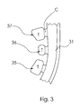
- FIG. 3 is an enlarged view of a portion of the one arm of the embodiment shown in FIG. 1 .
- FIG. 4 is front view of the embodiment of our bulb gripper shown in FIG. 1 attached to a stake when the bulb gripper is positioned co-linear with a centerline through the stake portion.
- FIG. 5 is front view of the embodiment shown in FIG. 3 when the bulb gripper is positioned substantially perpendicular to a centerline through the stake portion.
- FIG. 6 is perspective view of the embodiment as shown in FIG. 5 .
- FIG. 7 is perspective view of two of the stakes shown in FIGS. 4 and 5 holding a portion of a string of decorative lights with the bulb portion of the light bulbs being held above the bulb gripper.
- FIG. 8 is a side view of a decorative light being held by a portion of the bulb gripper as in FIG. 7 .
- FIG. 9 is a sectional view taken along the line IX-IX in FIG. 8 .
- FIG. 10 is a perspective view of the embodiment as shown in FIG. 1 attached to a mounting structure that can hold the head of a suction cup.
- FIG. 11 is a perspective view of the embodiment as shown in FIG. 1 attached to a mounting structure which can be attached to a gutter or shingles.
- FIG. 12 is a perspective view of the embodiment as shown in FIG. 1 attached to a mounting structure which can be attached to siding.
- a bulb gripper for a decorative light holder which has a U-shaped body with projections on the interior surface that enable the bulb gripper to securely hold a mini-light, or a C7 light or a C9 light as well as the newer C4, C5, C6, C12 and G28 sizes.
- This bulb gripper can be on a stake or attached to a housing that enables the bulb gripper to be attached to a gutter, siding, shingles or other structures.
- FIG. 1 A first present preferred embodiment of our bulb gripper is shown in FIG. 1 .
- the bulb gripper 10 has two arms 31 , 32 attached to a base 33 that together form a U-shaped body 30 .
- the U-shaped body is attached to a stake or housing which is used to place the decorative light at a desired location.
- the interior surface of each arm of the body has an inward tooth 34 near the opening followed by three spaced apart projections 35 , 36 , 37 .
- a smaller U-shaped projection 38 is at the base of the body. This smaller U-shaped projection 38 is sized to hold a mini-light. Because a mini-light has a bulb which is straight, the U-shaped projection is intended to grip mini lights by the socket and C3, C4, C5, and some smaller diameter C6 lights at the neck.
- the flats 39 at the ends of the U-shaped projection, along with tooth 34 and three projections 35 , 36 , 37 on each arm 31 , 32 define a circular opening that is sized to receive and securely hold the socket of a C7 light.
- the arms can flex outward so that the body can receive and securely hold the socket containing a C9, C12 or new G-sized decorative light.
- LED lights have become available that differ somewhat in size from their incandescent counterparts and are sold in new sizes called C4, C5 and C6.
- the socket can also vary in size depending upon the manufacturer.
- the bulb gripper disclosed here can be used to securely hold traditional decorative lights as well as the newer sizes of LED decorative lights.
- the bulb gripper 10 engages the decorative light 40 just above the top of the socket 41 and the neck of the bulb 42 , except for mini-lights which do not have a narrower neck.
- the projections 35 , 36 , 37 on each arm 31 , 32 that project inward from the U-shaped body of the bulb gripper are thin and form a ledge which supports the decorative light and prevents the light from moving up or down.
- the ledge helps the arms securely hold the light bulb in an upright vertical position shown in FIG. 7 and assures that all of the lights bulbs in a set are held the same position.
- the projections 35 , 36 , 37 that form the ledge may be mid-way between the top surfaces and the bottom surfaces of the arms or close to either the top surfaces or the bottom surfaces of the arms.
- the ledge may be formed by a single projection on each arm rather than multiple projections on each arm as shown in the drawings.
- FIG. 2 A second present preferred embodiment 4 of the bulb gripper is shown in FIG. 2 .
- This embodiment is similar to the first embodiment but has projections 33 a and 33 b at the base of the U-shaped body 30 . These projections are sized and configured to hold a mini-light.
- the projections 35 , 36 , and 37 as well as projections 33 a seen in FIG. 2 each preferably consists of a tab portion T connected to the arm 31 , 32 by a narrower connector portion C.
- the narrower connector enables the tab to flex up or down without causing the arm to twist.
- the arms may twist as the light bulb is inserted.
- Putting slots in the ledge is only partially effective in reducing rigidity and will not eliminate the twisting or distortion problem that may be encountered when the bulb is inserted between the arms. Also, adding slots would create stress concentrations at the ends of the slots between the flanges.
- FIGS. 4, 5 and 6 show the first embodiment of the bulb gripper attached to a stake 1 .
- the stake shown in FIGS. 4, 5 and 6 has a top portion 15 attached to an elongated shaft 2 having a pointed end.
- the bulb gripper 10 is pivotably attached to the inner surface of the top 15 by a hinge 25 such that the bulb gripper can be moved from a position which is co-linear with a centerline through the stake shown in FIG. 4 to a position which is substantially perpendicular to the centerline through the stake shown in FIGS. 5, 6 and 7 .
- the outer surface of the top portion 15 is curved and may have a series of parallel ribs that run across this surface. This configuration makes it easy to push the device into the ground.
- FIG. 10 shows the first embodiment 10 attached to a mounting structure 50 having a slot 52 that is sized to receive the head of a suction cup.
- the suction cup can be attached to a window or mirror.
- FIG. 11 shows the first embodiment 10 attached to a mounting structure 60 which can be attached to a gutter or shingles.
- the bulb gripper is attached to the mounting structure by a hinge 63 .
- a tab on the top of the bulb gripper can engage a first arm 61 on the housing 60 to hold the bulb gripper in a first locked position.
- a second tab on the bottom of the bulb gripper can engage a second arm 62 on the housing 60 to hold the bulb gripper in a second locked position.
- FIG. 12 shows another embodiment of the bulb gripper 10 a , which is similar to the first embodiment of the bulb gripper shown in FIG. 1 , attached to another mounting structure 70 that can be attached to siding.
- the U-shaped mini-light holder 38 a is connected to the base 33 of the U-shaped body 30 by a connector.
- the housing 70 has a hook 72 that can hold a rope light.
- the decorative light holder is made entirely of plastic.
- plastic we prefer to use polypropylene.
- the product could be made of a comparable plastic which permits the arms in the bulb gripper to flex.
Landscapes
- Engineering & Computer Science (AREA)
- General Engineering & Computer Science (AREA)
- Non-Portable Lighting Devices Or Systems Thereof (AREA)
Abstract
Description
Claims (7)
Priority Applications (1)
| Application Number | Priority Date | Filing Date | Title |
|---|---|---|---|
| US15/856,627 US10323830B2 (en) | 2016-12-29 | 2017-12-28 | Bulb gripper for holding decorative lights |
Applications Claiming Priority (2)
| Application Number | Priority Date | Filing Date | Title |
|---|---|---|---|
| US201662440122P | 2016-12-29 | 2016-12-29 | |
| US15/856,627 US10323830B2 (en) | 2016-12-29 | 2017-12-28 | Bulb gripper for holding decorative lights |
Publications (2)
| Publication Number | Publication Date |
|---|---|
| US20180187867A1 US20180187867A1 (en) | 2018-07-05 |
| US10323830B2 true US10323830B2 (en) | 2019-06-18 |
Family
ID=62711497
Family Applications (1)
| Application Number | Title | Priority Date | Filing Date |
|---|---|---|---|
| US15/856,627 Active US10323830B2 (en) | 2016-12-29 | 2017-12-28 | Bulb gripper for holding decorative lights |
Country Status (1)
| Country | Link |
|---|---|
| US (1) | US10323830B2 (en) |
Cited By (3)
| Publication number | Priority date | Publication date | Assignee | Title |
|---|---|---|---|---|
| US10837627B1 (en) * | 2019-06-21 | 2020-11-17 | Ulta-Lit Tree Company | Clip for holding a light bulb parallel to a light string |
| US20240133541A1 (en) * | 2021-11-29 | 2024-04-25 | Canny Systems, LLC | Light stake |
| US20250108764A1 (en) * | 2023-09-29 | 2025-04-03 | Ford Global Technologies, Llc | Integrated holder assembly for a vehicle door |
Families Citing this family (11)
| Publication number | Priority date | Publication date | Assignee | Title |
|---|---|---|---|---|
| US10247391B2 (en) * | 2016-10-21 | 2019-04-02 | Adams Mfg. Corp. | Stake for holding a decorative light |
| US11927327B1 (en) | 2019-02-22 | 2024-03-12 | Dawn Scheurle | Multipurpose bracket and a method using the same |
| USD917082S1 (en) * | 2020-09-30 | 2021-04-20 | Yiwu Puhong Trading Co., Ltd | Lamps |
| USD916334S1 (en) * | 2020-09-30 | 2021-04-13 | Yiwu Puhong Trading Co., Ltd | Lamps |
| USD917081S1 (en) * | 2020-09-30 | 2021-04-20 | Yiwu Puhong Trading Co., Ltd | Lamps |
| US11674672B1 (en) * | 2021-09-24 | 2023-06-13 | Loren A. Roper | Bulb-holding gutter clip |
| US20230249891A1 (en) * | 2022-02-04 | 2023-08-10 | Jacobs Corporation | Shipping assembly for hammermill hammers |
| USD968209S1 (en) * | 2022-05-10 | 2022-11-01 | Shenzhen Fuyade Technology Co., Ltd. | Light clip |
| US12196395B2 (en) * | 2022-05-13 | 2025-01-14 | Tim Nichols | Clip and seal holiday light ground stakes |
| USD1029316S1 (en) * | 2022-07-01 | 2024-05-28 | Xianying Su | Lighted artificial twig tree |
| US12442521B2 (en) * | 2024-07-31 | 2025-10-14 | Guangdong Guanyi Lighting Co., LTD | Rotatably adjustable lamp fixing member |
Citations (14)
| Publication number | Priority date | Publication date | Assignee | Title |
|---|---|---|---|---|
| US4851977A (en) | 1988-08-05 | 1989-07-25 | Gary Products Group, Inc. | Bracket for decorative lighting |
| US4901212A (en) | 1989-01-17 | 1990-02-13 | Prickett Robert B | Rapidly adjustable decorative exterior trim lighting system |
| US4905131A (en) | 1988-08-05 | 1990-02-27 | Gary Products Group, Inc. | Bracket for decorative lighting |
| USD331360S (en) | 1991-05-08 | 1992-12-01 | Adams Mfg. Corp. | Hook for supporting Christmas lights adjacent roofing shingles |
| US5249108A (en) | 1992-05-29 | 1993-09-28 | Gary Products Group, Inc. | Multiple-position decorative light bracket |
| US5469344A (en) | 1993-09-20 | 1995-11-21 | Kotsakis; Ted | Support for decorative light string on a building |
| US5581956A (en) | 1995-02-02 | 1996-12-10 | Noma International, Inc. | Universal decoration mounting arrangement |
| US5632552A (en) * | 1996-04-16 | 1997-05-27 | Toyo Electric Manufacturing Co. Ltd. | Lamp holder having lockable cap with integral clamping elements |
| US5667174A (en) | 1995-01-13 | 1997-09-16 | Adams Mfg. Corp. | Decorative light stake |
| US5669709A (en) | 1996-01-11 | 1997-09-23 | Adams Mfg. Corp. | Decorative light holder |
| US5772166A (en) | 1994-04-13 | 1998-06-30 | Adams Mfg. Corp. | Mounting clip |
| US6328459B1 (en) | 2000-08-18 | 2001-12-11 | Adams Mfg. Corp. | Releasable holder |
| US8888337B2 (en) | 2011-12-13 | 2014-11-18 | Adams Mfg. Corp. | Decorative light clip |
| USD756764S1 (en) | 2015-11-04 | 2016-05-24 | Jamie Limber | Temporary support device for ornamental lighting |
-
2017
- 2017-12-28 US US15/856,627 patent/US10323830B2/en active Active
Patent Citations (14)
| Publication number | Priority date | Publication date | Assignee | Title |
|---|---|---|---|---|
| US4905131A (en) | 1988-08-05 | 1990-02-27 | Gary Products Group, Inc. | Bracket for decorative lighting |
| US4851977A (en) | 1988-08-05 | 1989-07-25 | Gary Products Group, Inc. | Bracket for decorative lighting |
| US4901212A (en) | 1989-01-17 | 1990-02-13 | Prickett Robert B | Rapidly adjustable decorative exterior trim lighting system |
| USD331360S (en) | 1991-05-08 | 1992-12-01 | Adams Mfg. Corp. | Hook for supporting Christmas lights adjacent roofing shingles |
| US5249108A (en) | 1992-05-29 | 1993-09-28 | Gary Products Group, Inc. | Multiple-position decorative light bracket |
| US5469344A (en) | 1993-09-20 | 1995-11-21 | Kotsakis; Ted | Support for decorative light string on a building |
| US5772166A (en) | 1994-04-13 | 1998-06-30 | Adams Mfg. Corp. | Mounting clip |
| US5667174A (en) | 1995-01-13 | 1997-09-16 | Adams Mfg. Corp. | Decorative light stake |
| US5581956A (en) | 1995-02-02 | 1996-12-10 | Noma International, Inc. | Universal decoration mounting arrangement |
| US5669709A (en) | 1996-01-11 | 1997-09-23 | Adams Mfg. Corp. | Decorative light holder |
| US5632552A (en) * | 1996-04-16 | 1997-05-27 | Toyo Electric Manufacturing Co. Ltd. | Lamp holder having lockable cap with integral clamping elements |
| US6328459B1 (en) | 2000-08-18 | 2001-12-11 | Adams Mfg. Corp. | Releasable holder |
| US8888337B2 (en) | 2011-12-13 | 2014-11-18 | Adams Mfg. Corp. | Decorative light clip |
| USD756764S1 (en) | 2015-11-04 | 2016-05-24 | Jamie Limber | Temporary support device for ornamental lighting |
Cited By (7)
| Publication number | Priority date | Publication date | Assignee | Title |
|---|---|---|---|---|
| US10837627B1 (en) * | 2019-06-21 | 2020-11-17 | Ulta-Lit Tree Company | Clip for holding a light bulb parallel to a light string |
| US11248775B2 (en) | 2019-06-21 | 2022-02-15 | Ulta-Lit Tree Company | Clip for holding a light bulb parallel to a light string |
| US20240133541A1 (en) * | 2021-11-29 | 2024-04-25 | Canny Systems, LLC | Light stake |
| US12498106B2 (en) * | 2021-11-29 | 2025-12-16 | Canny Systems, LLC | Light stake |
| US12504154B2 (en) | 2021-11-29 | 2025-12-23 | Canny Systems, LLC | Light stake with bulb socket |
| US20250108764A1 (en) * | 2023-09-29 | 2025-04-03 | Ford Global Technologies, Llc | Integrated holder assembly for a vehicle door |
| US12522148B2 (en) * | 2023-09-29 | 2026-01-13 | Ford Global Technologies, Llc | Integrated holder assembly for a vehicle door |
Also Published As
| Publication number | Publication date |
|---|---|
| US20180187867A1 (en) | 2018-07-05 |
Similar Documents
| Publication | Publication Date | Title |
|---|---|---|
| US10323830B2 (en) | Bulb gripper for holding decorative lights | |
| US10247391B2 (en) | Stake for holding a decorative light | |
| US5667174A (en) | Decorative light stake | |
| US6328459B1 (en) | Releasable holder | |
| US10180242B2 (en) | Decorative light clip for gutters and shingles | |
| US5772166A (en) | Mounting clip | |
| US8888337B2 (en) | Decorative light clip | |
| US6076938A (en) | Hinged hanging simulated icicle frame | |
| US1895656A (en) | Clip for attaching electric lights to christmas trees | |
| US7055980B2 (en) | Decorative tree lamp | |
| US6644836B1 (en) | Apparatus for hanging rope lights from a gutter | |
| US20020000504A1 (en) | Christmas lights holder | |
| US5481444A (en) | Miniature light holder | |
| US6299118B1 (en) | Plant holder | |
| US20070114340A1 (en) | Eaves clip | |
| US5868490A (en) | Decorative lighting system in cluster arrangement | |
| US9335451B2 (en) | Arrangements of decorative elements, lighting fixtures, and methods for providing illumination | |
| CN101542200A (en) | Lighting device with decoration | |
| US2205496A (en) | Ornament and lamp support for use on christmas trees, etc. | |
| US7278765B2 (en) | Window candle holder | |
| US20040129846A1 (en) | Apparatus for hanging decorative lights from a rail or gutter | |
| US4888671A (en) | Ornamental strip light mounting means | |
| US6193396B1 (en) | Hanging holder for decorations | |
| US20160150903A1 (en) | Frame for an ornamental decoration | |
| US5562269A (en) | Mini bulb holder |
Legal Events
| Date | Code | Title | Description |
|---|---|---|---|
| FEPP | Fee payment procedure |
Free format text: ENTITY STATUS SET TO UNDISCOUNTED (ORIGINAL EVENT CODE: BIG.); ENTITY STATUS OF PATENT OWNER: LARGE ENTITY |
|
| FEPP | Fee payment procedure |
Free format text: ENTITY STATUS SET TO SMALL (ORIGINAL EVENT CODE: SMAL); ENTITY STATUS OF PATENT OWNER: LARGE ENTITY |
|
| AS | Assignment |
Owner name: ADAMS MFG. CORP., PENNSYLVANIA Free format text: ASSIGNMENT OF ASSIGNORS INTEREST;ASSIGNORS:ADAMS, WILLIAM E., IV;GOODWORTH, MATTHEW;HARPER, KEVIN A.;SIGNING DATES FROM 20171226 TO 20171228;REEL/FRAME:045205/0666 |
|
| AS | Assignment |
Owner name: UBS AG, LONDON BRANCH, AS AGENT, GREAT BRITAIN Free format text: SECURITY INTEREST;ASSIGNOR:ADAMS MFG. CORP.;REEL/FRAME:047975/0860 Effective date: 20181221 |
|
| STPP | Information on status: patent application and granting procedure in general |
Free format text: NOTICE OF ALLOWANCE MAILED -- APPLICATION RECEIVED IN OFFICE OF PUBLICATIONS |
|
| FEPP | Fee payment procedure |
Free format text: ENTITY STATUS SET TO UNDISCOUNTED (ORIGINAL EVENT CODE: BIG.); ENTITY STATUS OF PATENT OWNER: LARGE ENTITY |
|
| STCF | Information on status: patent grant |
Free format text: PATENTED CASE |
|
| MAFP | Maintenance fee payment |
Free format text: PAYMENT OF MAINTENANCE FEE, 4TH YEAR, LARGE ENTITY (ORIGINAL EVENT CODE: M1551); ENTITY STATUS OF PATENT OWNER: LARGE ENTITY Year of fee payment: 4 |
|
| AS | Assignment |
Owner name: ADAMS MFG. CORP., PENNSYLVANIA Free format text: RELEASE BY SECURED PARTY;ASSIGNOR:UBS AG, LONDON BRANCH, IN ITS CAPACITY AS SECURITY AGENT FOR THE SECURED PARTIES;REEL/FRAME:071236/0860 Effective date: 20250403 |
|
| AS | Assignment |
Owner name: BANK HAPOALIM B.M., ISRAEL Free format text: SECURITY INTEREST;ASSIGNOR:ADAMS MFG. CORP.;REEL/FRAME:071644/0110 Effective date: 20250617 |