US1031755A - Mixing device for internal-combustion engines or the like. - Google Patents
Mixing device for internal-combustion engines or the like. Download PDFInfo
- Publication number
- US1031755A US1031755A US65708911A US1911657089A US1031755A US 1031755 A US1031755 A US 1031755A US 65708911 A US65708911 A US 65708911A US 1911657089 A US1911657089 A US 1911657089A US 1031755 A US1031755 A US 1031755A
- Authority
- US
- United States
- Prior art keywords
- mixer
- engine
- valve
- cylinder
- charge
- Prior art date
- Legal status (The legal status is an assumption and is not a legal conclusion. Google has not performed a legal analysis and makes no representation as to the accuracy of the status listed.)
- Expired - Lifetime
Links
Images



Classifications
-
- F—MECHANICAL ENGINEERING; LIGHTING; HEATING; WEAPONS; BLASTING
- F02—COMBUSTION ENGINES; HOT-GAS OR COMBUSTION-PRODUCT ENGINE PLANTS
- F02M—SUPPLYING COMBUSTION ENGINES IN GENERAL WITH COMBUSTIBLE MIXTURES OR CONSTITUENTS THEREOF
- F02M21/00—Apparatus for supplying engines with non-liquid fuels, e.g. gaseous fuels stored in liquid form
- F02M21/02—Apparatus for supplying engines with non-liquid fuels, e.g. gaseous fuels stored in liquid form for gaseous fuels
Definitions
- WALTER c wEs'rAwAY, 0E BELVIDERE, ILLINoIs.
- My invention belongs to that general class of devices known as mixers for internal combustion engines or the like, and relates particularly to an improved fluid cooled mixing device, adapted to .be arranged within the cylinder, preferably at the intake port, for mixing or vco-mingling the ⁇ charge as it enters, or just after it has entered the engine cylinder. y
- the device has among its objects the production of a simple, durable, ellicient and V satisfactory device of the kind described for use Wherever found applicable.
- the present invention is in the nature of an improvement over that yshown and described in my pending application, Serial No. 636,316, filed June 3o, 1911.
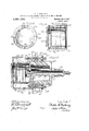
- Figure 1 is a sectional view of a portion of an engine cylinder head or wall, provided with my mixing device.
- Fig. 2 is a cross sectional view taken substantially on line 2, 2 of Fig. 1.
- Fig.'3 is a sectional view taken substantially on line 3, 3 of Fig. l.
- Fig. 4 yis a sectional view taken Substantially 'on line 4, 4 of Fi 3.
- Fig. 5 is a sectional view similar toFig; 1 of another form of my device.
- Fig. 6 1 s a sectional view of the same taken substantially on line 6, 6 of Fig. 5.
- Fig. 7 is a sectional view of a simplified form of my device.
- Fig. 1 is a sectional view of a simplified form of my device.
- FIG. 8 is a plan view. of the same removed from thecyllnder wall' or head.
- Fig. 9 is ab sectional view of another form of my device, in which'the cylinder wall or head and mixer are formed integrally.
- Fi 10 is a sectional view of another form o my device, showing the application of the same to what is known as a two-cycle engine, and Fig. 11 is an end elevation of the same, a portion broken away to show the construction.
- Y is a plan view. of the same removed from thecyllnder wall' or head.
- Fig. 9 is ab sectional view of another form of my device, in which'the cylinder wall or head and mixer are formed integrally.
- Fi 10 is a sectional view of another form o my device, showing the application of the same to what is known as a two-cycle engine, and
- Fig. 11 is an end elevation of the same, a portion broken away to show the construction.
- valve mechanism comprises a valve casing 5 provided with a suitable inlet v7, the casing being secured to the cylinder head or wall by bolts .9 extended through the flange 8, or in an' equivalent manner.
- the casing 5 may be extended Within the cylinder any desired distance. As shown, it extends slightly beyond the interior face of the cylinder head.
- the casing .5. is provided with a valve seat 6 for the in take valve 4, the valve being provided with a stem 11 extending without the casing.
- the valve is normally maintained on its seatvby a resilient member 18, arranged between the collar 19 and the casing 5, 20 being an adjustable stopv for limiting the travel of the valve.”
- a resilient member 18, arranged between the collar 19 and the casing 5, 20 being an adjustable stopv for limiting the travel of the valve.
- auxiliary valve being normally maintained upon its seat by a resilient member or spring 21 arranged between the collar 22 and the end of the stem 11.
- a resilient member or spring 21 arranged between the collar 22 and the end of the stem 11.
- an adjustable stop or limiting member 23 for the auxiliary valve may be arranged on the stem.
- the stem 11 is provided with one or .more openings 17 therethrough, to form air inlets, so that as the charge of combustible is drawn through the'inlet 7 and through the chamber 10, past the valve 4, a charge of air or other suitable .fluid is drawn through the openings 17,
- the mixei ⁇ j yvhieli is arranged within the cylinderfmprises'a shellv 25 provided with a pluralityof slots 27 therethe' shell VV25 y'being surrounded' by stru "tion A'shinwiifth two shells are 'coni' nected together so as to'nfo'rm' a...coolingi end of titions 40 at the slots 27, the slots extending through .the outer shell.
- this construction chambers 30 are formed between the slots by the/two shells, and the partitions 40 and the chamber 30 between the two ends 26 and 29.
- the mixer is cooled by admitting a suitable cooling duid, such as water, air or the like, thusbe seen that-the mixer is provided with Huid coolingv jacket, which revents the same from becoming overheateti.)
- a suitable cooling duid such as water, air or the like
- Huid coolingv jacket which revents the same from becoming overheateti.
- theizid is conducted to the mixer through a pipe 37, and through a duct 36 in the casing 5 to the ⁇ chamber or duct 32 between the twoshells, and thence passes through the chambers 30, and out through the duct v34:, duct 38 and pipe 39.
- the sizes of the ducts 36 and 38 may be made as desired, the size of the same depending .upon whether it is desired to cool the. parts as thecharge passes through the valve casing- 5.
- head instead of through the 41 represents the cylinderwall or head provided with a cooling chamber 42, if desired.
- the 'valve casing45 provided.' with an. inlet 47, fthefvalvef arrangement bei'n'g similar tothat previously described.Av 'these figures comprises an inner shell and .end 48.
- the" ⁇ niixcr is extended at each side, as at 5l and 52 (sce Fig.
- the extended parts being provided ⁇ with ducts 60 and 61, connected witlr ⁇ the water jacket spaces 53.
- the extended parts v 51 and 52 are extended as at 55 and 56 (see Fig. 5) and the mixer. secured in position by extending pipes 57 ⁇ and58 'through 'the ⁇ wall 41, and engagingfthe mixer. Nuts 59, the exterior of the cylinder maintain theA mixer in position.
- the mixer in this cas' ⁇ is aizid or ledge 79 may be Fig. 7. This figure illus- 7 2, as illustrated in ⁇ trates the si'mpliicdvalvc construct-ion previouslymentioned,and also the water jacket or space in the-wall- 65 isomtted.
- Fig. 9 illustrates cylinder vhead wallfflzo Referring to the Afigure, 80 represeiits'tlie cylinder head rovided with an intake port 81, the charge being admitted through the intake port 81,
- the cylinder head is extended at-85and 87 to forint-hc two shells, through which are-thecorresponding prvvdedlwitli slots 86.
- the two.; shells; are
- Each side is preferably extended as at 90 on one side and at 91 on the other side, so as to form passages 92 and 93 to which a cooling iiuid may be conlbustion engine of 'mixing means arranged ducted to and from the mixer by the pipes 96 andi97 and ducts 9 4 and 95.
- a cross section of this form of mixer Will be sub stantially the same as a cross section of the mixer illustrated in Fig. 5.
- the mixers previously described are particularly applicable for four-cycle engines, .and may be modified as found necessary, for use on a two-cycle engine. InFigs.
- 10 and 11 l illustrate the use of a similar fluid cooling mixer on atWo-cycle engine.
- This type of engine is so Well known that a description of t-he same ⁇ is unnecessary other than to say that 100 represents the cylinder Wall, provided With a Water jacket space 101, if desired, and With a combustible or charge passageway 103 to the intake port 102.
- the mixer which comprises an inner shell 104 surrounded by an outer shell 105, the two being connected so as to term a jacket, into which the cooling fluid may be introduced.
- the two shells are connected at 107 and slotted at 106, so -that a plurality of cooling chambers 108 are formed' about the slots, and a chamber 1081 between the two ends of the shells.
- Fluid is admitted to cool the mixer through a pipe 111, or its equivalent, and passes through the ducts 109 between the shells to the duct 110, and thence out through a pipe 112, or its equivalent.
- the ingoing charge is thoroughly and efficiently mixed or co-mingled before being tired.
- the mixer being cooled by the cooling fluid, is prevented from being heated by the firing in tl@y cylinder, so that it does not heat enough to iire the charge.
- the parts being cooled there is no tendency for back firing.
- any style or valve mechanism may be used, and it will be particularly noted that in all the forms illustrated in Figs. 1 to 9, the valve, valvecasing, etc., are prevented from becoming overheated.
- the mixer is preferably arrangedl within the cylinder in proximity to thev ineke port, but in the 'tvvocycle type of en-k nie, owing, to ⁇ the construction of the engine, it is arranged Withinthe intake port..
- this construction of engine itis practically the same as if in the engine cylinder.
- An auxiliary mixer for combustion engines consisting of a shell provided with a plurality of openings therethrough, means for securing the same on the interior of the engine cylinder in the path of the ingoing charge, and means for cooling said mixer.
- a Huid cooled mixer and means for securing the same atfthe inner side of the intake port of an internal combustion engine.
- An auxiliary mixer for combustion engines consisting of a plurality of spaced shells, provided with a plurality of open- Y ings therethrough, said shells integrally connected about said openings.
- a mixer for internal combustion engines comprising a shell provided with a ofslotstherethrough, means for plurality of slots therethrough, means for Acooling the exterior of said shell about said slots, means for securing said shell to the interior of the engine inthe path ⁇ of the lCombustible thereto, and means for conduct- V ⁇ inga cooling fluid -to the mixer.
- a mixer having Aan internal combustion engine, comprlsing an .inner shell and an outer -shell spaced therefrom, said shells each arranged with a plurality of corresponding slots andconnected together about said slots to vform chambers between the p. slots and shells, and means for conducting a 2o.
- bustion engine of mixing means arranged' at the inner side of the intake port in the path of the ingoing charge, and means for cooling said mixing means.
Landscapes
- Engineering & Computer Science (AREA)
- Chemical & Material Sciences (AREA)
- Chemical Kinetics & Catalysis (AREA)
- General Chemical & Material Sciences (AREA)
- Oil, Petroleum & Natural Gas (AREA)
- Combustion & Propulsion (AREA)
- Mechanical Engineering (AREA)
- General Engineering & Computer Science (AREA)
- Cylinder Crankcases Of Internal Combustion Engines (AREA)
Description
W. C. WESTAWAY.
MIXING DEVICE FOR INTERNAL GOMBUSTION ENGINES OE. THE LIKE.
APPLICATION FILED 001227, 1911.
Patented July 9, 1912.
4 SHEETS-SHEET 1.
, W. C. WESTAWAY.
MIXING DEVICE FOR INTERNAL GOMBUSTION ENGINES 0R THE LIKE.
APPLICATION FILED 0`GT.27*, 1911. .I
Patented July 9, 1912.
jr Y l' @hun f5 @fu/@.7
Q6/MQ@ WQG. WESTAWAY.
MIXING DEVICE POR INTERNAL COMBUSTION ENGINES 0R THE LIKE.
APPLICATION FILED ooT.27,1911. 1,031,755.
Patented July 9, 1912.
4 SHEETS-SHEET 3.
W'. C. WESTAWAY. MIXING DEVICE FOR INTERNAL COMBUSTION ENGINES 0R THE LIKE.
4 SHEETS-SHEET 4.
In strains- PATENT oEEIcE.
WALTER c. wEs'rAwAY, 0E BELVIDERE, ILLINoIs.
llIXlN'Y DEVICE FOR INTERNAL-COMBUSTION ENGINES 0R THE LIKE.
Specicaton of Letters Patent.
Patented July 9, 1912.
Application filed October 27, 1911. Serial 11o. 657,089.
To all whom t may concern.' v
Be it known that I, WALTER C. WESTA- WAY, a citizen of the United States, residing at Belvidere, in the county ofv Boone and State of Illinois, have invented certain new andv useful Improvements in Mixing Devices for 'Internal-Combustion Engines or the Like, of which the following is a description.
My invention belongs to that general class of devices known as mixers for internal combustion engines or the like, and relates particularly to an improved fluid cooled mixing device, adapted to .be arranged within the cylinder, preferably at the intake port, for mixing or vco-mingling the `charge as it enters, or just after it has entered the engine cylinder. y
, The device has among its objects the production of a simple, durable, ellicient and V satisfactory device of the kind described for use Wherever found applicable. y
The present invention is in the nature of an improvement over that yshown and described in my pending application, Serial No. 636,316, filed June 3o, 1911.
To this end my invention consists in the novel construction, arrangement and combinationo-f parts herein shown and described, and more particularly pointed out in the claims.
In the drawings, wherein like reference characters indicate like or vcprresponding parts, Figure 1 is a sectional view of a portion of an engine cylinder head or wall, provided with my mixing device. Fig. 2 is a cross sectional view taken substantially on line 2, 2 of Fig. 1. Fig.'3 is a sectional view taken substantially on line 3, 3 of Fig. l. Fig. 4 yis a sectional view taken Substantially 'on line 4, 4 of Fi 3. Fig. 5 is a sectional view similar toFig; 1 of another form of my device. Fig. 6 1s a sectional view of the same taken substantially on line 6, 6 of Fig. 5.' Fig. 7 is a sectional view of a simplified form of my device. Fig. 8 is a plan view. of the same removed from thecyllnder wall' or head. Fig. 9 is ab sectional view of another form of my device, in which'the cylinder wall or head and mixer are formed integrally. Fi 10 is a sectional view of another form o my device, showing the application of the same to what is known as a two-cycle engine, and Fig. 11 is an end elevation of the same, a portion broken away to show the construction. Y
Referring particularly to Figs. l to 4, in which one form of my device is shown, 1 represents the c linder head or wall, which may be provide with the usual water jacket space 2, if. desired. The charge is admitted to the interior of the cylinder through the intake port 3, suitable valve mechanism being provided, that shown being similar to that described in my pending application above mentioned. This valve mechanism comprises a valve casing 5 provided with a suitable inlet v7, the casing being secured to the cylinder head or wall by bolts .9 extended through the flange 8, or in an' equivalent manner. The casing 5 may be extended Within the cylinder any desired distance. As shown, it extends slightly beyond the interior face of the cylinder head. The casing .5.is provided with a valve seat 6 for the in take valve 4, the valve being provided with a stem 11 extending without the casing. lThe valve is normally maintained on its seatvby a resilient member 18, arranged between the collar 19 and the casing 5, 20 being an adjustable stopv for limiting the travel of the valve.""Where 'it is desired to admit air to theinterior of the"cy"linder simultaneously with the admission of the charge, I form the stem 1l hollow, or with a chamber 12 therein, and extend the valve 4 to form a valve seat 15" for an auxiliary valve 14. v The auxiliary valve 14 is. provided with a stem 16, which extends without the valve stem 11, the auxiliary valve being normally maintained upon its seat by a resilient member or spring 21 arranged between the collar 22 and the end of the stem 11. If desired, an adjustable stop or limiting member 23 for the auxiliary valve may be arranged on the stem. The stem 11 is provided with one or .more openings 17 therethrough, to form air inlets, so that as the charge of combustible is drawn through the'inlet 7 and through the chamber 10, past the valve 4, a charge of air or other suitable .fluid is drawn through the openings 17,
through the chamber 12 and stem 11, past the auxiliary valve 14, the charge of combustible and air being mixed or co-mingled upon entering the cvhnder. 'It may be menl el aimed, and i wish it ciedriy understood, that the auxiliary`valve arrangement described may be omitted,
struction. The mixei`j yvhieli is arranged within the cylinderfmprises'a shellv 25 provided with a pluralityof slots 27 therethe' shell VV25 y'being surrounded' by stru "tion A'shinwiifth two shells are 'coni' nected together so as to'nfo'rm' a...coolingi end of titions 40 at the slots 27, the slots extending through .the outer shell. By 'this construction chambers 30 are formed between the slots by the/two shells, and the partitions 40 and the chamber 30 between the two ends 26 and 29. The mixer is cooled by admitting a suitable cooling duid, such as water, air or the like, thusbe seen that-the mixer is provided with Huid coolingv jacket, which revents the same from becoming overheateti.) The mixer and its =jacl et may be secured in position within the cylinder ,in any desired way, as shown the other shell is extended as at 31 and arranged to screw upon the extended end ofthe casing 5. Infthe form shown in theseigurs, the luid is conducted to the mixer through a pipe 37, and through a duct 36 in the casing 5 to the` chamber or duct 32 between the twoshells, and thence passes through the chambers 30, and out through the duct v34:, duct 38 and pipe 39.
-For convenience in positioningvthe mixer,
the face ofthe two` shells, which bear against the casing-5, maybe'provided with vg'rooves'33 and 35, so that if in turning the mixer in place,tlie ducts 32 and34 do not register 'with the ducts 36 and 38, the-,cooling fluid will be-conducted to the ducts 32 and 38 through the grooves, whicharemost clearly illustratcdin Fig. 2. Anysuitable means may be employed for providing the flow or supply Vof cooling fluid, as for example, a pump, .agravity tank, or the like (not shown.) .1 In the. construction shown in Figs.- 1 to 4, it is not necessary to extend the pipes through thecylinder head or walls,
so that the device is Aapplicable on any type of engine. The sizes of the ducts 36 and 38 may be made as desired, the size of the same depending .upon whether it is desired to cool the. parts as thecharge passes through the valve casing- 5.
vIn the construction-shown invv Fig. 5, the cooling fluidI is conducted'v to the mixer through pipes, which extend through the cylinder wall or .valve casing.- vReferring to- Figs.' 5 and 6,
or their equivalents, on
to the chambers 30. It will' obvious,
tended through-fthe wall and from the space 78.A
head instead of through the 41 represents the cylinderwall or head provided with a cooling chamber 42, if desired.
Through `the intake poit 4 3 is arranged the 'valve casing45, provided.' with an. inlet 47, fthefvalvef arrangement bei'n'g similar tothat previously described.Av 'these figures comprises an inner shell and .end 48. About the in iierrshellis an. outer The mixer shown in lshell 50 and 'head' `the` outer' shell .being also slotted to correspond with the slots in Vv'the inner shell, and the two shells integrally connected so as vto .formLcooling chamber-SL53 between the slots. In this form the"`niixcr is extended at each side, as at 5l and 52 (sce Fig. 6), the extended parts being provided`\ with ducts 60 and 61, connected witlr` the water jacket spaces 53. The extended parts v 51 and 52 are extended as at 55 and 56 (see Fig. 5) and the mixer. secured in position by extending pipes 57` and58 'through 'the` wall 41, and engagingfthe mixer. Nuts 59, the exterior of the cylinder maintain theA mixer in position.
The operation 'oivthis form ot' niixeris siiii-`` ilar to that previously described, the cooling fluid being admitted through one of the pipes to the mixer and conducted away by the other pipe. jIf desired, the cooling fluid for the mixer may be taken from thewater jacket42, but this construction 4beinggso In the form sho'iwn in- .95 I have not considered it necessary` is a simplified construction, v65-'represents the engine wallfor head, 67 a valve casing.
for the valve 68,66 t-he intake port to the engine cylinder, land 69 tween theni, the-parts being extendedas at 74 and 75 substantially similar tothe coiif struction shown in;.Fig..5 for securingthc the inlet to the ca`s-. ing 67. The mixer in this cas'` is a luid or ledge 79 may be Fig. 7. This figure illus- 7 2, as illustrated in `trates the si'mpliicdvalvc construct-ion previouslymentioned,and also the water jacket or space in the-wall- 65 isomtted.
and mixer vformed-integrally.
Fig. 9 illustrates cylinder vhead wallfflzo Referring to the Afigure, 80 represeiits'tlie cylinder head rovided with an intake port 81, the charge being admitted through the intake port 81,
. through the casing 82, suitable valve nicchanism being provided. The cylinder head is extended at-85and 87 to forint-hc two shells, through which are-thecorresponding prvvdedlwitli slots 86. The two.; shells; are
nected together, or in an equivalent manner, about the slots, similar to the other constructions. Each side is preferably extended as at 90 on one side and at 91 on the other side, so as to form passages 92 and 93 to which a cooling iiuid may be conlbustion engine of 'mixing means arranged ducted to and from the mixer by the pipes 96 andi97 and ducts 9 4 and 95. A cross section of this form of mixer Will be sub stantially the same as a cross section of the mixer illustrated in Fig. 5. `The mixers previously described are particularly applicable for four-cycle engines, .and may be modified as found necessary, for use on a two-cycle engine. InFigs. 10 and 11 l illustrate the use of a similar fluid cooling mixer on atWo-cycle engine. This type of engine is so Well known that a description of t-he same `is unnecessary other than to say that 100 represents the cylinder Wall, provided With a Water jacket space 101, if desired, and With a combustible or charge passageway 103 to the intake port 102. At the intake port is arranged the mixer, which comprises an inner shell 104 surrounded by an outer shell 105, the two being connected so as to term a jacket, into which the cooling fluid may be introduced. The two shells are connected at 107 and slotted at 106, so -that a plurality of cooling chambers 108 are formed' about the slots, and a chamber 1081 between the two ends of the shells. Fluid is admitted to cool the mixer through a pipe 111, or its equivalent, and passes through the ducts 109 between the shells to the duct 110, and thence out through a pipe 112, or its equivalent.
In any of the constructions shown, the ingoing charge is thoroughly and efficiently mixed or co-mingled before being tired. The mixer being cooled by the cooling fluid, is prevented from being heated by the firing in tl@y cylinder, so that it does not heat enough to iire the charge. The parts being cooled, there is no tendency for back firing. As before mentioned, any style or valve mechanism, Where desired, may be used, and it will be particularly noted that in all the forms illustrated in Figs. 1 to 9, the valve, valvecasing, etc., are prevented from becoming overheated. In the four-cycletypeot engine, the mixer is preferably arrangedl within the cylinder in proximity to thev ineke port, but in the 'tvvocycle type of en-k eine, owing, to `the construction of the engine, it is arranged Withinthe intake port.. However, in this construction of engine, itis practically the same as if in the engine cylinder.
Having thus described my invention, it is obvious that various immaterial modifications may be made in the same Wit-hout departing from the spirit of my invent-ion, hence I do not Wish to be understood as limiting myself to the exact form, construction, arrangement or combination of parts herein shown and described, or uses mentioned. a
What I claim as new and desire to secure by Letters Patent is l; The combinatlon 1n an internal com- 70 Within the cylinder in the path of theingoing charge, and means for cooling said. mixing means. 75
2. The combination of Aan internal combustion engine, a mixer, means for securing the said mixerin the interior of the engine cylinder in proximity to the intake port, and means for coolingsaid mixer.
3. The combination in an internal comb'ustion engine of a mixer, means for secure ing the mixer in the interior of the en ine cylinder, said mixer provided with a uid chamber therein,- and means for conducting a cooling fluid to said chamber.
4. The combination in an internal` ombustion engine of a mixer, means for secur inor the mixer in the interior o the engine cylinder, proximate 4the intake port, said vmixer provided with a fluid' chamber there# in, and means for conducting a. cooling iuid to and from said" chamber. f i
5. An auxiliary mixer for combustion engines, consisting of a shell provided with a plurality of openings therethrough, means for securing the same on the interior of the engine cylinder in the path of the ingoing charge, and means for cooling said mixer.
6. The combination in an internal combustion engine of a cylinder provided with an intake port, a mixer arranged at said port, means for cooling said mixer, means for controlling the admission ofa charge' into said mixer, and means for'simultane- 105 ously controlling the admission of air to said mixer simultaneously Wit-h the admise sion of the charge therein. y
7. Thecombin'ation in an internal combustion engine of a cylinder provided with 110 an intake port, a mixer arranged at said port provided'with a cooling chamber therein, means for conducting a cooling iiuid to said chamber, means forcontrolling the admission of a charge into said mixer, al' means for simultaneously controlling the admission of air to said mixer simultaneously withthe admission of the charge therein.
8. A Huid cooled mixer, and means for securing the same atfthe inner side of the intake port of an internal combustion engine.
9. An auxiliary mixer for combustion engines, consisting of a plurality of spaced shells, provided with a plurality of open- Y ings therethrough, said shells integrally connected about said openings.
10. A mixer for internal combustion engines, comprising a shell provided with a ofslotstherethrough, means for plurality of slots therethrough, means for Acooling the exterior of said shell about said slots, means for securing said shell to the interior of the engine inthe path `of the lCombustible thereto, and means for conduct- V`inga cooling fluid -to the mixer. I 12. A mixer having Aan internal combustion engine, comprlsing an .inner shell and an outer -shell spaced therefrom, said shells each arranged with a plurality of corresponding slots andconnected together about said slots to vform chambers between the p. slots and shells, and means for conducting a 2o.
13, lThe combination in an internal comfluidr to saidl chambers.
bustion engine of mixing means arranged' at the inner side of the intake port in the path of the ingoing charge, and means for cooling said mixing means.
14. The combination in an internal combustion engine of a mixer arranged at the inner side of the intakeport in the path of the ingoing charge, said mixer consisting of a plurality of spaced shells suitably connected together to form a Water jacket, and
-Copes of lthis patent may` be, obtained for ve cents each, by addressing the. Commissioner ofrlaten'ts,
Washington, D. C. f j
Priority Applications (1)
| Application Number | Priority Date | Filing Date | Title |
|---|---|---|---|
| US65708911A US1031755A (en) | 1911-10-27 | 1911-10-27 | Mixing device for internal-combustion engines or the like. |
Applications Claiming Priority (1)
| Application Number | Priority Date | Filing Date | Title |
|---|---|---|---|
| US65708911A US1031755A (en) | 1911-10-27 | 1911-10-27 | Mixing device for internal-combustion engines or the like. |
Publications (1)
| Publication Number | Publication Date |
|---|---|
| US1031755A true US1031755A (en) | 1912-07-09 |
Family
ID=3100047
Family Applications (1)
| Application Number | Title | Priority Date | Filing Date |
|---|---|---|---|
| US65708911A Expired - Lifetime US1031755A (en) | 1911-10-27 | 1911-10-27 | Mixing device for internal-combustion engines or the like. |
Country Status (1)
| Country | Link |
|---|---|
| US (1) | US1031755A (en) |
-
1911
- 1911-10-27 US US65708911A patent/US1031755A/en not_active Expired - Lifetime
Similar Documents
| Publication | Publication Date | Title |
|---|---|---|
| US2244323A (en) | Internal combustion engine | |
| US1579332A (en) | Internal-combustion engine | |
| US1905140A (en) | Valve for internal combustion engines | |
| US1083265A (en) | Combustion-engine. | |
| US566263A (en) | Bela wolf | |
| US1292634A (en) | Internal-combustion engine. | |
| US1260860A (en) | Cylinder-cover for combustion-engines. | |
| US1130872A (en) | Internal-combustion engine. | |
| US1260859A (en) | Engine-cylinder. | |
| US1177162A (en) | Cylinder of internal-combustion engines. | |
| US1785861A (en) | Air-cooled internal-combustion engine | |
| US1164673A (en) | Internal-combustion engine. | |
| US1144424A (en) | Internal-combustion engine. | |
| US1198334A (en) | Internal-combustion engine. | |
| NO742623L (en) | ||
| US1282602A (en) | Valve for internal-combustion engines. | |
| US1292477A (en) | Valve mechanism for explosive-engines. | |
| US746840A (en) | Explosive-engine. | |
| US1144422A (en) | Internal-combustion engine. | |
| US1149670A (en) | Explosive-engine. | |
| US1399262A (en) | Internal-combustion engine | |
| US2310134A (en) | Rotary valve engine | |
| US745701A (en) | Cooling device for explosion-engines. | |
| US932184A (en) | Internal-combustion engine. | |
| US904086A (en) | Internal-combustion engine. |