US10317036B2 - Light guiding device and vehicle lamp - Google Patents

Light guiding device and vehicle lamp Download PDF

Info

Publication number
US10317036B2
US10317036B2 US15/519,409 US201515519409A US10317036B2 US 10317036 B2 US10317036 B2 US 10317036B2 US 201515519409 A US201515519409 A US 201515519409A US 10317036 B2 US10317036 B2 US 10317036B2
Authority
US
United States
Prior art keywords
light
light guide
guiding device
component
medium component
Prior art date
Legal status (The legal status is an assumption and is not a legal conclusion. Google has not performed a legal analysis and makes no representation as to the accuracy of the status listed.)
Active, expires
Application number
US15/519,409
Other versions
US20170234500A1 (en
Inventor
Zhao FANG
Chen Chen
Yagui GAO
Current Assignee (The listed assignees may be inaccurate. Google has not performed a legal analysis and makes no representation or warranty as to the accuracy of the list.)
Valeo Lighting Hubei Technical Center Co Ltd
Original Assignee
Valeo Lighting Hubei Technical Center Co Ltd
Priority date (The priority date is an assumption and is not a legal conclusion. Google has not performed a legal analysis and makes no representation as to the accuracy of the date listed.)
Filing date
Publication date
Application filed by Valeo Lighting Hubei Technical Center Co Ltd filed Critical Valeo Lighting Hubei Technical Center Co Ltd
Assigned to VALEO LIGHTING HUBEI TECHNICAL CENTER CO. LTD. reassignment VALEO LIGHTING HUBEI TECHNICAL CENTER CO. LTD. ASSIGNMENT OF ASSIGNORS INTEREST (SEE DOCUMENT FOR DETAILS). Assignors: CHEN, CHEN, FANG, Zhao, GAO, Yagui
Publication of US20170234500A1 publication Critical patent/US20170234500A1/en
Application granted granted Critical
Publication of US10317036B2 publication Critical patent/US10317036B2/en
Active legal-status Critical Current
Adjusted expiration legal-status Critical

Links

Images

Classifications

    • FMECHANICAL ENGINEERING; LIGHTING; HEATING; WEAPONS; BLASTING
    • F21LIGHTING
    • F21SNON-PORTABLE LIGHTING DEVICES; SYSTEMS THEREOF; VEHICLE LIGHTING DEVICES SPECIALLY ADAPTED FOR VEHICLE EXTERIORS
    • F21S43/00Signalling devices specially adapted for vehicle exteriors, e.g. brake lamps, direction indicator lights or reversing lights
    • F21S43/20Signalling devices specially adapted for vehicle exteriors, e.g. brake lamps, direction indicator lights or reversing lights characterised by refractors, transparent cover plates, light guides or filters
    • F21S43/235Light guides
    • BPERFORMING OPERATIONS; TRANSPORTING
    • B60VEHICLES IN GENERAL
    • B60QARRANGEMENT OF SIGNALLING OR LIGHTING DEVICES, THE MOUNTING OR SUPPORTING THEREOF OR CIRCUITS THEREFOR, FOR VEHICLES IN GENERAL
    • B60Q1/00Arrangement of optical signalling or lighting devices, the mounting or supporting thereof or circuits therefor
    • B60Q1/0011Arrangement of optical signalling or lighting devices, the mounting or supporting thereof or circuits therefor with light guides for distributing the light between several lighting or signalling devices
    • FMECHANICAL ENGINEERING; LIGHTING; HEATING; WEAPONS; BLASTING
    • F21LIGHTING
    • F21SNON-PORTABLE LIGHTING DEVICES; SYSTEMS THEREOF; VEHICLE LIGHTING DEVICES SPECIALLY ADAPTED FOR VEHICLE EXTERIORS
    • F21S43/00Signalling devices specially adapted for vehicle exteriors, e.g. brake lamps, direction indicator lights or reversing lights
    • F21S43/20Signalling devices specially adapted for vehicle exteriors, e.g. brake lamps, direction indicator lights or reversing lights characterised by refractors, transparent cover plates, light guides or filters
    • F21S43/235Light guides
    • F21S43/236Light guides characterised by the shape of the light guide
    • F21S43/237Light guides characterised by the shape of the light guide rod-shaped
    • FMECHANICAL ENGINEERING; LIGHTING; HEATING; WEAPONS; BLASTING
    • F21LIGHTING
    • F21SNON-PORTABLE LIGHTING DEVICES; SYSTEMS THEREOF; VEHICLE LIGHTING DEVICES SPECIALLY ADAPTED FOR VEHICLE EXTERIORS
    • F21S43/00Signalling devices specially adapted for vehicle exteriors, e.g. brake lamps, direction indicator lights or reversing lights
    • F21S43/20Signalling devices specially adapted for vehicle exteriors, e.g. brake lamps, direction indicator lights or reversing lights characterised by refractors, transparent cover plates, light guides or filters
    • F21S43/235Light guides
    • F21S43/242Light guides characterised by the emission area
    • F21S43/245Light guides characterised by the emission area emitting light from one or more of its major surfaces
    • FMECHANICAL ENGINEERING; LIGHTING; HEATING; WEAPONS; BLASTING
    • F21LIGHTING
    • F21SNON-PORTABLE LIGHTING DEVICES; SYSTEMS THEREOF; VEHICLE LIGHTING DEVICES SPECIALLY ADAPTED FOR VEHICLE EXTERIORS
    • F21S43/00Signalling devices specially adapted for vehicle exteriors, e.g. brake lamps, direction indicator lights or reversing lights
    • F21S43/20Signalling devices specially adapted for vehicle exteriors, e.g. brake lamps, direction indicator lights or reversing lights characterised by refractors, transparent cover plates, light guides or filters
    • F21S43/235Light guides
    • F21S43/247Light guides with a single light source being coupled into the light guide
    • FMECHANICAL ENGINEERING; LIGHTING; HEATING; WEAPONS; BLASTING
    • F21LIGHTING
    • F21SNON-PORTABLE LIGHTING DEVICES; SYSTEMS THEREOF; VEHICLE LIGHTING DEVICES SPECIALLY ADAPTED FOR VEHICLE EXTERIORS
    • F21S43/00Signalling devices specially adapted for vehicle exteriors, e.g. brake lamps, direction indicator lights or reversing lights
    • F21S43/20Signalling devices specially adapted for vehicle exteriors, e.g. brake lamps, direction indicator lights or reversing lights characterised by refractors, transparent cover plates, light guides or filters
    • F21S43/27Attachment thereof

Definitions

  • the present disclosure relates to the lighting field, in particular to a light guiding device and a vehicle lamp having the light guiding device.
  • light guide media adapted to transmit and guide a light are well-known, for example, optical fibers, light guide bars.
  • certain fixing components such as grippers, clips are typically provided on the light guide media.
  • These fixing components may change the original optical guide construction of a light guiding device such that the light traveling in the light guide media may be leaked into the fixing components.
  • Such leaked light may exit the fixing components in an undesired direction to cause an undesired bright spot.
  • the light guide media are used in a vehicle lamp, such undesired bright spot may cause poor lit effects of the vehicle lamp.
  • An object of the present disclosure is to provide a light guiding device that can avoid undesired bright spots due to light leakage at the fixing component.
  • Another object of the present disclosure is to provide a vehicle lamp comprising the light guiding device, which can avoid the interference of the above undesired bright spot to the lit effect of the lamp.
  • An embodiment of the present invention provides a light guiding device, comprising:
  • a light guide medium component configured to guide a light to be transmitted through it from one end thereof to another end thereof;
  • a light guide fixing component arranged on the light guide medium component and configured to fix the light guide medium component
  • the light guide medium component and the light guide fixing component are both at least partly transparent, and wherein the light guide fixing component has a light directing portion configured to direct the light, which is leaked from the light guide medium component into the light guide fixing component, to exit the light guide fixing component in a direction deviated from a predetermined direction.
  • the light directing portion has one or more light deflection outgoing face/faces through which the light leaked from the light guide medium component into the light guide fixing component passes to exit the light guide fixing component, and the light deflection outgoing face/faces is/are oriented to deviate the light passing through the light deflection outgoing face/faces, from the predetermined direction.
  • the light directing portion has one or more light deflection incidence face/faces by which the light leaked from the light guide medium component is deflected into the light guide fixing component.
  • the light deflection outgoing face/faces is/are formed by a cut corner.
  • the light deflection outgoing face/faces is/are a cambered surface/cambered surfaces, or an inclined surface/inclined surfaces with respect to a surface of the light guide medium component.
  • the orientation of the light deflection outgoing face/faces depends on the refractive index of the light guide medium component, the refractive index of the light guide fixing component, an incident direction of the light leaked from the light guide medium component into the light guide fixing component and the predetermined direction.
  • the light deflection outgoing face/faces is/are arranged at an angle/angles of 20 degrees to 90 degrees relative to the surface of the light guide medium component.
  • the light directing portion further has an intermediate light deflection face arranged in an optical path between the light deflection outgoing face/faces and the location at which the light is leaked into the light guide fixing component to deflect the light in advance before the light reaches the light deflection outgoing face/faces.
  • the predetermined direction is a direction which is visible to human eyes.
  • the light guide medium component and the light guide fixing component are formed integrally.
  • the light guide medium component transmits the light by means of total reflection.
  • a light source which is located at the outside of an end of the light guide medium component and has a light emitting direction facing toward the end of the light guide medium component.
  • the predetermined direction is the direction along which a lamp light is emitted from the lamp.
  • At least one above embodiments of the present disclosure can control the light emitting direction of the light by providing a light directing portion on the light guide fixing component.
  • the light emitted from the light guide fixing component may be prevented from forming an undesired bright spot in undesired directions.
  • FIG. 1 is a schematic view showing a light guiding device according to an embodiment of the present invention
  • FIG. 2 is a schematic view showing a light guiding device according to another embodiment of the present invention.
  • FIG. 3 is a schematic view showing a light guiding device according to a further embodiment of the present invention.
  • FIG. 1 schematically shows a light guiding device 100 according to an embodiment of the present invention.
  • the light guiding device 100 comprises a light guide medium component 101 and a light guide fixing component 102 .
  • the light guide medium component 101 such as an optical fiber or a light guide bar, is configured to guide a light to be transmitted through it from one end thereof to another end thereof.
  • the light guide fixing component 102 is arranged on the light guide medium component 101 and configured to fix the light guide medium component 101 .
  • the light guide fixing component 102 has a light directing portion 1022 configured to direct the light 103 , which is leaked from the light guide medium component 101 into the light guide fixing component 102 , to exit the light guide fixing component 102 in a direction deviated from a predetermined direction.
  • the light guide fixing component 102 may be provided with a connecting portion 1021 such as a connecting hole, or a connecting groove.
  • the light guide medium component 101 and the light guide fixing component 102 may both be made from at least partly transparent material, on other words, the light guide medium component 101 and the light guide fixing component 102 are both at least partly transparent themselves.
  • the light guide fixing component 102 may affect, or even destroy the optical guide construction of the light guide medium component 101 locally such that the light is leaked into the light guide fixing component 102 from the light guide medium component 101 .
  • the light guide medium component 101 such as an optical fiber, a light guide bar or a light guide plate, may transmit the light by means of total reflection to reduce the power consumption loss. However, it needs the reflection of the light at a reflective interface to meet the total reflection condition. In this way, the light guide medium component 101 needs to have a certain shape, for example of uniform cylindrical shape.
  • the arrangement of the light guide fixing component 102 may change the local shape of the light guide medium component 101 such that the total reflection condition will not be met at the original reflective interface of the light 103 . Thus, the light 103 may be leaked into the light guide fixing component 102 from the light guide medium component 101 and finally exit the light guide fixing component 102 .
  • the light directing portion 1022 that is configured to control the direction along which the light leaked into the light guide fixing component 102 exits the light guide fixing component 102 . If the direction is not controlled, the light exiting the light guide fixing component 102 may cause an undesired bright spot.
  • the light directing portion 1022 can direct the light, which is leaked from the light guide medium component 101 into the light guide fixing component 102 , to exit the light guide fixing component 102 in a direction deviated from the predetermined direction.
  • the predetermined direction may be a direction which is visible to human eyes and the bright spot produced in the direction may cause the eyes to feel uncomfortable.
  • the predetermined direction may be a direction in which a lamp emits a light and the bright spot produced in the direction may change the light intensity distribution to affect the lighting or lit effect.
  • the light directing portion 1022 may avoid producing an undesired bright spot and thus correspondingly avoid the above issues caused by such bright spot.
  • the light directing portion 1022 may have one or more light deflection outgoing face/faces 1023 through which the light leaked from the light guide medium component 101 into the light guide fixing component 102 passes to exit the light guide fixing component 102 .
  • the light deflection outgoing face/faces 1023 is/are oriented to deviate the light passing through the light deflection outgoing face/faces 1023 , from the predetermined direction.
  • change of the direction of the light deflection outgoing face/faces 1023 can change the direction in which the light exits the light deflection outgoing face/faces 1023 due to refraction effect.
  • the direction in which the light exits the light deflection outgoing face/faces 1023 may be deviated from the predetermined direction to avoid undesired bright spot presented in the undesired directions.
  • FIGS. 1-2 only show one light deflection outgoing face 1023 , it should be understood that the present invention is not limited to this.
  • the light directing portion 1022 may provide two or more light deflection outgoing faces 1023 in a plurality of possible light exit directions of the light guide fixing component 102 respectively to control the light exit direction.
  • the light guide medium component 101 may have the same refractive index as that of the light guide fixing component 102 or have different refractive index from that of the light guide fixing component 102 .
  • the light deflection outgoing face/faces 1023 is/are formed by a cut corner, as illustrated in FIG. 1 . Such arrangement is simple and effective. However, the light deflection outgoing face/faces 1023 may be formed by other means such as supplement.
  • the light deflection outgoing face/faces 1023 may be a cambered surface/cambered surfaces or an inclined surface/inclined surfaces for example inclined with respect to a surface of the light guide medium component 101 , to meet the requirements for controlling various light exit directions.
  • the orientation of the light deflection outgoing face/faces 1023 may be determined depending on factors such as the refractive index of the light guide medium component 101 , the refractive index of the light guide fixing component 102 , an incident direction of the light leaked from the light guide medium component 101 into the light guide fixing component 102 and the above predetermined direction (i.e., the light exit direction to be avoided).
  • the light deflection outgoing face/faces 1023 is/are arranged at an angle/angles of 20 degrees to 90 degrees, for example 30 degrees to 70 degrees such as 40 degrees to 60 degrees relative to the surface of the light guide medium component 101 .
  • the light directing portion 1022 further has one or more light deflection incidence face/faces 1025 by which the light leaked from the light guide medium component 101 is deflected into the light guide fixing component 102 .
  • the light guide medium component 101 may have a reflective index different from that of the light guide fixing component 102 .
  • the light deflection incidence face/faces 1025 may also deflect the light, i.e., change the travel direction of the light.
  • the light deflection incidence face/faces 1025 also can change the direction in which the light exits the light guide fixing component 102 .
  • the light deflection outgoing face/faces 1023 and the light deflection incidence face/faces 1025 may be used in combination.
  • the direction in which the light exits the light guide fixing component 102 will have a greater adjustable range so as to control the light exit direction better to be deviated from the predetermined direction.
  • the light deflection incidence face/faces 1025 is/are located on the upstream while the light deflection outgoing face/faces 1023 is/are located on the downstream.
  • the light deflection incidence face/faces 1025 may also be formed by a cut corner or by other means such as supplement.
  • the light deflection incidence face/faces 1025 may also be a cambered surface/cambered surfaces or an inclined surface/inclined surfaces for example inclined with respect to a surface of the light guide medium component 101 .
  • the orientation of the light deflection incidence face/faces 1025 may also be determined depending on factors such as the refractive index of the light guide medium component 101 , the refractive index of the light guide fixing component 102 , the incident direction of the light leaked from the light guide medium component 101 into the light guide fixing component 102 and the above predetermined direction (i.e., the light exit direction to be avoided).
  • the light directing portion 1022 further has an intermediate light deflection face 1024 arranged in an optical path between the light deflection outgoing face/faces 1023 and the location at which the light is leaked into the light guide fixing component 102 , on other words, the light leaked into the light guide fixing component 102 will be deflected by the intermediate light deflection face 1024 before it reaches the light deflection outgoing face/faces 1023 . It may deflect the light in advance before the light reaches the light deflection outgoing face/faces 1023 .
  • the intermediate light deflection face 1024 may be configured to further enhance the deflection angle of the exiting light.
  • the light guide medium component 101 and the light guide fixing component 102 may be formed integrally. It contributes to reduction of manufacturing process and assembling errors. However, it is not necessary, the light guide medium component 101 and the light guide fixing component 102 may also be manufactured separately and then assembled together.
  • the present disclosure also provides a vehicle lamp comprising: the light guiding device 100 , 100 ′, 100 ′′ as described in any one of the above embodiments and a light source 200 .
  • the light source 200 may be located at the outside of an end of the light guide medium component 101 and have a light emitting direction facing toward the end of the light guide medium component 101 , as illustrated in FIGS. 1-3 .
  • the predetermined direction i.e., the light exit direction to be avoided
  • the predetermined direction may be the direction along which a lamp light is emitted from the lamp. It may prevent undesired bright spot caused by light leakage from being contained in the lighting beam of the vehicle lamp.

Landscapes

  • Engineering & Computer Science (AREA)
  • General Engineering & Computer Science (AREA)
  • Mechanical Engineering (AREA)
  • Non-Portable Lighting Devices Or Systems Thereof (AREA)
  • Lighting Device Outwards From Vehicle And Optical Signal (AREA)
  • Planar Illumination Modules (AREA)
  • Light Guides In General And Applications Therefor (AREA)

Abstract

The present utility model discloses a light guiding device and a vehicle lamp. The light guiding device includes a light guide medium component configured to allow light to be transmitted through it from one end thereof to another end thereof. A light guide fixing component is arranged on the light guide medium component and configured to fix the light guide medium component, wherein the light guide medium component and the light guide fixing component are both at least partly made of a transparent material. The light guide fixing component has a light directing portion configured to direct the light leaked from the light guide medium component into the light guide fixing component to exit the light guide fixing component away from a predetermined direction. Using the light guiding device and the vehicle lamp according to the present utility model can prevent light exiting the light guide fixing component from forming undesirable light spots in an undesirable direction.

Description

CROSS-REFERENCE TO RELATED APPLICATION
This application claims the benefit of Chinese Patent Application No. 201420592601.1 filed on Oct. 14, 2014 in the State Intellectual Property Office of China, the disclosure of which is incorporated in entirety herein by reference.
BACKGROUND OF THE INVENTION
Field of the Invention
The present disclosure relates to the lighting field, in particular to a light guiding device and a vehicle lamp having the light guiding device.
Description of the Related Art
In the lighting field, light guide media adapted to transmit and guide a light are well-known, for example, optical fibers, light guide bars. However, in order to fix the light guide media, certain fixing components such as grippers, clips are typically provided on the light guide media. These fixing components may change the original optical guide construction of a light guiding device such that the light traveling in the light guide media may be leaked into the fixing components. Such leaked light may exit the fixing components in an undesired direction to cause an undesired bright spot. For example, when the light guide media are used in a vehicle lamp, such undesired bright spot may cause poor lit effects of the vehicle lamp.
SUMMARY OF THE INVENTION
An object of the present disclosure is to provide a light guiding device that can avoid undesired bright spots due to light leakage at the fixing component.
Another object of the present disclosure is to provide a vehicle lamp comprising the light guiding device, which can avoid the interference of the above undesired bright spot to the lit effect of the lamp.
An embodiment of the present invention provides a light guiding device, comprising:
a light guide medium component configured to guide a light to be transmitted through it from one end thereof to another end thereof; and
a light guide fixing component arranged on the light guide medium component and configured to fix the light guide medium component,
wherein the light guide medium component and the light guide fixing component are both at least partly transparent, and wherein the light guide fixing component has a light directing portion configured to direct the light, which is leaked from the light guide medium component into the light guide fixing component, to exit the light guide fixing component in a direction deviated from a predetermined direction.
In an embodiment, the light directing portion has one or more light deflection outgoing face/faces through which the light leaked from the light guide medium component into the light guide fixing component passes to exit the light guide fixing component, and the light deflection outgoing face/faces is/are oriented to deviate the light passing through the light deflection outgoing face/faces, from the predetermined direction.
In an embodiment, the light directing portion has one or more light deflection incidence face/faces by which the light leaked from the light guide medium component is deflected into the light guide fixing component.
In an embodiment, the light deflection outgoing face/faces is/are formed by a cut corner.
In an embodiment, the light deflection outgoing face/faces is/are a cambered surface/cambered surfaces, or an inclined surface/inclined surfaces with respect to a surface of the light guide medium component.
In an embodiment, the orientation of the light deflection outgoing face/faces depends on the refractive index of the light guide medium component, the refractive index of the light guide fixing component, an incident direction of the light leaked from the light guide medium component into the light guide fixing component and the predetermined direction.
In an embodiment, the light deflection outgoing face/faces is/are arranged at an angle/angles of 20 degrees to 90 degrees relative to the surface of the light guide medium component.
In an embodiment, the light directing portion further has an intermediate light deflection face arranged in an optical path between the light deflection outgoing face/faces and the location at which the light is leaked into the light guide fixing component to deflect the light in advance before the light reaches the light deflection outgoing face/faces.
In an embodiment, the predetermined direction is a direction which is visible to human eyes.
In an embodiment, the light guide medium component and the light guide fixing component are formed integrally.
In an embodiment, the light guide medium component transmits the light by means of total reflection.
An embodiment of the present invention provides a vehicle lamp comprising:
the light guiding device as described in any one of the above embodiments; and
a light source which is located at the outside of an end of the light guide medium component and has a light emitting direction facing toward the end of the light guide medium component.
In an embodiment, the predetermined direction is the direction along which a lamp light is emitted from the lamp.
At least one above embodiments of the present disclosure can control the light emitting direction of the light by providing a light directing portion on the light guide fixing component. By means of the light guiding device and vehicle lamp according to the present disclosure, the light emitted from the light guide fixing component may be prevented from forming an undesired bright spot in undesired directions.
BRIEF DESCRIPTION OF THE DRAWINGS
FIG. 1 is a schematic view showing a light guiding device according to an embodiment of the present invention;
FIG. 2 is a schematic view showing a light guiding device according to another embodiment of the present invention; and
FIG. 3 is a schematic view showing a light guiding device according to a further embodiment of the present invention.
DETAILED DESCRIPTION OF PREFERRED EMBODIMENTS
The embodiments of the present invention will be further explained below with reference to the figures and examples. Throughout the description, same or similar reference numbers indicate the same or similar members. The following embodiments along with the figures are only used to explain the general concept of the present invention, instead of being intended to limit the scope of the present invention.
FIG. 1 schematically shows a light guiding device 100 according to an embodiment of the present invention. The light guiding device 100 comprises a light guide medium component 101 and a light guide fixing component 102. The light guide medium component 101, such as an optical fiber or a light guide bar, is configured to guide a light to be transmitted through it from one end thereof to another end thereof. The light guide fixing component 102 is arranged on the light guide medium component 101 and configured to fix the light guide medium component 101. The light guide fixing component 102 has a light directing portion 1022 configured to direct the light 103, which is leaked from the light guide medium component 101 into the light guide fixing component 102, to exit the light guide fixing component 102 in a direction deviated from a predetermined direction. As an example, in order to fix the light guide medium component 101 on an apparatus such as a wall, a casing, or a shield, the light guide fixing component 102 may be provided with a connecting portion 1021 such as a connecting hole, or a connecting groove. The light guide medium component 101 and the light guide fixing component 102 may both be made from at least partly transparent material, on other words, the light guide medium component 101 and the light guide fixing component 102 are both at least partly transparent themselves.
Arrangement of the light guide fixing component 102 may affect, or even destroy the optical guide construction of the light guide medium component 101 locally such that the light is leaked into the light guide fixing component 102 from the light guide medium component 101. In an example, the light guide medium component 101 such as an optical fiber, a light guide bar or a light guide plate, may transmit the light by means of total reflection to reduce the power consumption loss. However, it needs the reflection of the light at a reflective interface to meet the total reflection condition. In this way, the light guide medium component 101 needs to have a certain shape, for example of uniform cylindrical shape. The arrangement of the light guide fixing component 102 may change the local shape of the light guide medium component 101 such that the total reflection condition will not be met at the original reflective interface of the light 103. Thus, the light 103 may be leaked into the light guide fixing component 102 from the light guide medium component 101 and finally exit the light guide fixing component 102.
It is the light directing portion 1022 that is configured to control the direction along which the light leaked into the light guide fixing component 102 exits the light guide fixing component 102. If the direction is not controlled, the light exiting the light guide fixing component 102 may cause an undesired bright spot. The light directing portion 1022 can direct the light, which is leaked from the light guide medium component 101 into the light guide fixing component 102, to exit the light guide fixing component 102 in a direction deviated from the predetermined direction. For example, the predetermined direction may be a direction which is visible to human eyes and the bright spot produced in the direction may cause the eyes to feel uncomfortable. Or in another example, the predetermined direction may be a direction in which a lamp emits a light and the bright spot produced in the direction may change the light intensity distribution to affect the lighting or lit effect. The light directing portion 1022 may avoid producing an undesired bright spot and thus correspondingly avoid the above issues caused by such bright spot.
As an example, the light directing portion 1022 may have one or more light deflection outgoing face/faces 1023 through which the light leaked from the light guide medium component 101 into the light guide fixing component 102 passes to exit the light guide fixing component 102. The light deflection outgoing face/faces 1023 is/are oriented to deviate the light passing through the light deflection outgoing face/faces 1023, from the predetermined direction. When the light guide fixing component 102 is made from the transparent materials, change of the direction of the light deflection outgoing face/faces 1023 can change the direction in which the light exits the light deflection outgoing face/faces 1023 due to refraction effect. By adjusting the direction of the light deflection outgoing face/faces 1023, for example an angle/angles of the light deflection outgoing face/faces 1023 relative to the surface of the light guide medium component 101, the direction in which the light exits the light deflection outgoing face/faces 1023 may be deviated from the predetermined direction to avoid undesired bright spot presented in the undesired directions. Although FIGS. 1-2 only show one light deflection outgoing face 1023, it should be understood that the present invention is not limited to this. For example, the light directing portion 1022 may provide two or more light deflection outgoing faces 1023 in a plurality of possible light exit directions of the light guide fixing component 102 respectively to control the light exit direction. Arrows in FIGS. 1 and 2 represent the travel direction of the light. As an example, the light guide medium component 101 may have the same refractive index as that of the light guide fixing component 102 or have different refractive index from that of the light guide fixing component 102. As an example, the light deflection outgoing face/faces 1023 is/are formed by a cut corner, as illustrated in FIG. 1. Such arrangement is simple and effective. However, the light deflection outgoing face/faces 1023 may be formed by other means such as supplement. As an example, the light deflection outgoing face/faces 1023 may be a cambered surface/cambered surfaces or an inclined surface/inclined surfaces for example inclined with respect to a surface of the light guide medium component 101, to meet the requirements for controlling various light exit directions. As an example, the orientation of the light deflection outgoing face/faces 1023 may be determined depending on factors such as the refractive index of the light guide medium component 101, the refractive index of the light guide fixing component 102, an incident direction of the light leaked from the light guide medium component 101 into the light guide fixing component 102 and the above predetermined direction (i.e., the light exit direction to be avoided). For example, the light deflection outgoing face/faces 1023 is/are arranged at an angle/angles of 20 degrees to 90 degrees, for example 30 degrees to 70 degrees such as 40 degrees to 60 degrees relative to the surface of the light guide medium component 101.
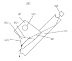
As an example, as illustrated in FIG. 3, the light directing portion 1022 further has one or more light deflection incidence face/faces 1025 by which the light leaked from the light guide medium component 101 is deflected into the light guide fixing component 102. In this case, the light guide medium component 101 may have a reflective index different from that of the light guide fixing component 102. Similar to the light deflection outgoing face/faces 1023, the light deflection incidence face/faces 1025 may also deflect the light, i.e., change the travel direction of the light. Thus, the light deflection incidence face/faces 1025 also can change the direction in which the light exits the light guide fixing component 102. As an example, the light deflection outgoing face/faces 1023 and the light deflection incidence face/faces 1025 may be used in combination. In this way, the direction in which the light exits the light guide fixing component 102 will have a greater adjustable range so as to control the light exit direction better to be deviated from the predetermined direction. In terms of the travel direction of the light, the light deflection incidence face/faces 1025 is/are located on the upstream while the light deflection outgoing face/faces 1023 is/are located on the downstream. Similar to the light deflection outgoing face/faces 1023, the light deflection incidence face/faces 1025 may also be formed by a cut corner or by other means such as supplement. Likewise, the light deflection incidence face/faces 1025 may also be a cambered surface/cambered surfaces or an inclined surface/inclined surfaces for example inclined with respect to a surface of the light guide medium component 101. And in an example, the orientation of the light deflection incidence face/faces 1025 may also be determined depending on factors such as the refractive index of the light guide medium component 101, the refractive index of the light guide fixing component 102, the incident direction of the light leaked from the light guide medium component 101 into the light guide fixing component 102 and the above predetermined direction (i.e., the light exit direction to be avoided).
In an example, as illustrated in FIG. 2, in the light guiding device 100′, the light directing portion 1022 further has an intermediate light deflection face 1024 arranged in an optical path between the light deflection outgoing face/faces 1023 and the location at which the light is leaked into the light guide fixing component 102, on other words, the light leaked into the light guide fixing component 102 will be deflected by the intermediate light deflection face 1024 before it reaches the light deflection outgoing face/faces 1023. It may deflect the light in advance before the light reaches the light deflection outgoing face/faces 1023. The intermediate light deflection face 1024 may be configured to further enhance the deflection angle of the exiting light. It can further improve the control of the light exit direction in comparison with the case provided with only the light deflection outgoing face/faces 1023. Such arrangement is in particular advantageous if the parts of the light guide fixing component 102 on both sides of the interface of the intermediate light deflection face 1024 have different refractive indexes from each other.
As an example, the light guide medium component 101 and the light guide fixing component 102 may be formed integrally. It contributes to reduction of manufacturing process and assembling errors. However, it is not necessary, the light guide medium component 101 and the light guide fixing component 102 may also be manufactured separately and then assembled together.
The present disclosure also provides a vehicle lamp comprising: the light guiding device 100, 100′, 100″ as described in any one of the above embodiments and a light source 200. The light source 200 may be located at the outside of an end of the light guide medium component 101 and have a light emitting direction facing toward the end of the light guide medium component 101, as illustrated in FIGS. 1-3. For example, the predetermined direction (i.e., the light exit direction to be avoided) may be the direction along which a lamp light is emitted from the lamp. It may prevent undesired bright spot caused by light leakage from being contained in the lighting beam of the vehicle lamp.
Although the present disclosure is provided with reference to figures, all of the embodiments shown in figures are intended to explain the preferred embodiments of the present invention by ways of examples, instead of being intended to limit the present invention.
Apparently, it would be appreciated by those skilled in the art that various changes or modifications may be made in the present disclosure without departing from the principles and spirit of the disclosure, which are intended to be covered by the present invention as long as these changes or modifications fall within the scope defined in the claims and their equivalents.

Claims (20)

What is claimed is:
1. A light guiding device comprising:
a light guide medium component configured to allow a light to be transmitted through it from one end thereof to another end thereof; and
a light guide fixing component arranged on the light guide medium component and configured to fix the light guide medium component, wherein the light guide medium component and the light guide fixing component are both at least partly transparent,
and wherein the light guide fixing component has a light directing portion configured to direct the light leaked from the light guide medium component into the light guide fixing component to exit the light guide fixing component away from a predetermined direction, the light direction portion including an intermediate light deflection face.
2. The light guiding device according to claim 1, wherein the light directing portion has one or more light deflection outgoing face/faces through which the light leaked from the light guide medium component into the light guide fixing component passes to exit the light guide fixing component, and the light deflection outgoing face/faces is/are oriented to deflect the light exiting it away from the predetermined direction.
3. The light guiding device according to claim 2, wherein the light directing portion has one or more light deflection incident face/faces, wherein light leaked from the light guide medium component is deflected by the light deflection incident face/faces and enters the light guide fixing component.
4. The light guiding device according to claim 2, wherein the light deflection outgoing face/faces is/are formed by a cut corner.
5. The light guiding device according to claim 2, wherein the light deflection outgoing face/faces is/are an inclined face/inclined faces or a cambered face/cambered faces inclined with respect to the surface of the light guide medium component.
6. The light guiding device according to claim 2, wherein the light deflection outgoing face/faces is/are configured to form an angle of 20° to 90° with the surface of the light guide medium component.
7. The light guiding device according to claim 2, wherein the orientation of the light deflection outgoing face/faces depends on the refractive index of the light guide medium component, the refractive index of the light guide fixing component, an incident direction of the light leaked from the light guide medium component into the light guide fixing component and the predetermined direction.
8. The light guiding device according to claim 2, wherein the intermediate light deflection face arranged in an optical path between the light deflection outgoing face/faces and the location at which the light is leaked into the light guide fixing component to deflect the light in advance before it reaches the light deflection outgoing face/faces.
9. The light guiding device according to claim 8, wherein the predetermined direction is a direction which is visible to human eyes.
10. The light guiding device according to claim 8, wherein the light guide medium component and the light guide fixing component are formed integrally.
11. The light guiding device according to claim 8, wherein the light guide medium component transmits the light by means of total reflection.
12. A vehicle lamp, comprising the light guiding device according to claim 1; and a light source located outside one end of the light guide medium component, and the light emission direction of the light source facing this end of the light guide medium component.
13. The vehicle lamp according to claim 12, wherein the predetermined direction is the direction along which lamp light is emitted from the vehicle lamp.
14. The light guiding device according to claim 1, wherein the predetermined direction is a direction which is visible to human eyes.
15. The light guiding device according to claim 1, wherein the light guide medium component and the light guide fixing component are formed integrally.
16. The light guiding according to claim 1, wherein the light guide medium component transmits the light by means of total reflection.
17. The light guiding device according to claim 2, wherein the predetermined direction is a direction which is visible to human eyes.
18. The light guiding device according to claim 2, wherein the light guide medium component and the light guide fixing component are formed integrally.
19. A vehicle lamp, comprising the light guiding device according to claim 2; and a light source located outside one end of the light guide medium component, and the light emission direction of the light source facing this end of the light guide medium component.
20. The vehicle lamp according to claim 19, wherein the predetermined direction is the direction along which lamp light is emitted from the vehicle lamp.
US15/519,409 2014-10-14 2015-10-14 Light guiding device and vehicle lamp Active 2036-02-02 US10317036B2 (en)

Applications Claiming Priority (4)

Application Number Priority Date Filing Date Title
CN201420592601.1 2014-10-14
CN201420592601U 2014-10-14
CN201420592601.1U CN204084130U (en) 2014-10-14 2014-10-14 Guiding device and car light
PCT/CN2015/091917 WO2016058530A1 (en) 2014-10-14 2015-10-14 Light guiding device and vehicle lamp

Publications (2)

Publication Number Publication Date
US20170234500A1 US20170234500A1 (en) 2017-08-17
US10317036B2 true US10317036B2 (en) 2019-06-11

Family

ID=52176846

Family Applications (1)

Application Number Title Priority Date Filing Date
US15/519,409 Active 2036-02-02 US10317036B2 (en) 2014-10-14 2015-10-14 Light guiding device and vehicle lamp

Country Status (4)

Country Link
US (1) US10317036B2 (en)
EP (1) EP3207307B1 (en)
CN (1) CN204084130U (en)
WO (1) WO2016058530A1 (en)

Families Citing this family (6)

* Cited by examiner, † Cited by third party
Publication number Priority date Publication date Assignee Title
CN204084130U (en) 2014-10-14 2015-01-07 法雷奥照明湖北技术中心有限公司 Guiding device and car light
FR3031793B1 (en) * 2015-01-15 2017-01-27 Valeo Iluminacion Sa VEHICLE LIGHT DEVICE IN WHICH A LIGHT GUIDE SUPPORTS ANOTHER LIGHT GUIDE
CN108105716A (en) * 2018-01-18 2018-06-01 上海小糸车灯有限公司 It can prevent the light guide installation foot mounting structure of lighting bright spot
FR3081538B1 (en) * 2018-05-23 2022-11-04 Psa Automobiles Sa OPTICAL UNIT LIGHT GUIDE, AT REAR END WITH FIXING BRACKETS PARTICIPATING IN PHOTON REFLECTION.
CN114509844B (en) * 2022-04-21 2022-06-21 联钢精密科技(中国)有限公司 Light guide device with gradual change extension function
WO2023219044A1 (en) * 2022-05-13 2023-11-16 株式会社小糸製作所 Vehicle lamp fitting

Citations (4)

* Cited by examiner, † Cited by third party
Publication number Priority date Publication date Assignee Title
US20060146555A1 (en) 2004-12-10 2006-07-06 Koito Manufacturing Co., Ltd. Vehicular lamp
US20120051077A1 (en) 2010-08-24 2012-03-01 Koito Manufacturing Co., Ltd. Vehicular lamp
US8752986B2 (en) 2012-02-21 2014-06-17 Toyota Motor Engineering & Manufacturing North America, Inc. Vehicle lamp assembly having uniform lit appearance
CN204084130U (en) 2014-10-14 2015-01-07 法雷奥照明湖北技术中心有限公司 Guiding device and car light

Family Cites Families (4)

* Cited by examiner, † Cited by third party
Publication number Priority date Publication date Assignee Title
TW200622326A (en) * 2004-09-15 2006-07-01 Nippon Sheet Glass Co Ltd Bar-shaped light guide, illumination unit and image-scannig device
US9266468B2 (en) * 2012-07-27 2016-02-23 Toyoda Gosei Co., Ltd. Linear lighting device
JP5794217B2 (en) * 2012-09-28 2015-10-14 豊田合成株式会社 Lighting device
DE102015007591A1 (en) * 2015-06-16 2016-12-22 Audi Ag Optical fiber for an interior or exterior light element of a motor vehicle

Patent Citations (4)

* Cited by examiner, † Cited by third party
Publication number Priority date Publication date Assignee Title
US20060146555A1 (en) 2004-12-10 2006-07-06 Koito Manufacturing Co., Ltd. Vehicular lamp
US20120051077A1 (en) 2010-08-24 2012-03-01 Koito Manufacturing Co., Ltd. Vehicular lamp
US8752986B2 (en) 2012-02-21 2014-06-17 Toyota Motor Engineering & Manufacturing North America, Inc. Vehicle lamp assembly having uniform lit appearance
CN204084130U (en) 2014-10-14 2015-01-07 法雷奥照明湖北技术中心有限公司 Guiding device and car light

Non-Patent Citations (1)

* Cited by examiner, † Cited by third party
Title
International Search Report and Written Opinion dated Jan. 7, 2016 in PCT/CN15/091917 filed Oct. 14, 2015.

Also Published As

Publication number Publication date
CN204084130U (en) 2015-01-07
WO2016058530A1 (en) 2016-04-21
EP3207307A4 (en) 2018-04-04
US20170234500A1 (en) 2017-08-17
EP3207307A1 (en) 2017-08-23
EP3207307B1 (en) 2019-11-06

Similar Documents

Publication Publication Date Title
US10317036B2 (en) Light guiding device and vehicle lamp
EP3456587B1 (en) Light beam adjusting device, vehicle lamp and motor vehicle
EP3379321B1 (en) Image display device and headup display equipped with image display device
JP6207384B2 (en) Illumination device and optical member
US8465180B2 (en) Optical element for asymmetric light distribution
US11041985B2 (en) Lightguides with asymmetric light extracting structures
CN103968326B (en) Lens and the lighting device with the lens
CN101622567A (en) Optical scanner and two-dimensional image display employing the same
US9310546B2 (en) Backlight unit and display device having the same
CN109253417B (en) Optical module and light source module
EP2573455A2 (en) Lamp with asymmetric luminous intensity
CN103308972A (en) Light guide plate and backlight module
US10018330B2 (en) Light flux control member, light-emitting device, and illumination device
US9182529B2 (en) Light guide element and lamp for controlling light beam angle
MX2016014006A (en) Extruded fiber optic light bar.
TWM508682U (en) Light guide bar
JP4899930B2 (en) LIGHT GUIDE, BACKLIGHT DEVICE, DISPLAY DEVICE, AND ELECTRONIC DEVICE
KR20120122642A (en) Reflective light source type light guide system of sidelight type backlight unit
JP2007165289A (en) Backlight module
CN107676732B (en) Light patterning device and lighting and/or signaling device
WO2016178369A1 (en) Light flux control member, light-emitting device, planar light-source device, and display device
KR20200036334A (en) lamp for vehicle
TWM446344U (en) Backlight module and optical lens thereof
US10738959B2 (en) Vehicular lamp fitting
US20140063845A1 (en) Light-guiding plate and plane illumination apparatus therewith

Legal Events

Date Code Title Description
AS Assignment

Owner name: VALEO LIGHTING HUBEI TECHNICAL CENTER CO. LTD., CH

Free format text: ASSIGNMENT OF ASSIGNORS INTEREST;ASSIGNORS:FANG, ZHAO;CHEN, CHEN;GAO, YAGUI;REEL/FRAME:042339/0965

Effective date: 20170424

STPP Information on status: patent application and granting procedure in general

Free format text: NOTICE OF ALLOWANCE MAILED -- APPLICATION RECEIVED IN OFFICE OF PUBLICATIONS

STPP Information on status: patent application and granting procedure in general

Free format text: PUBLICATIONS -- ISSUE FEE PAYMENT RECEIVED

STCF Information on status: patent grant

Free format text: PATENTED CASE

MAFP Maintenance fee payment

Free format text: PAYMENT OF MAINTENANCE FEE, 4TH YEAR, LARGE ENTITY (ORIGINAL EVENT CODE: M1551); ENTITY STATUS OF PATENT OWNER: LARGE ENTITY

Year of fee payment: 4