US10316977B2 - Multi-outlet check valve nozzle - Google Patents
Multi-outlet check valve nozzle Download PDFInfo
- Publication number
- US10316977B2 US10316977B2 US13/409,936 US201213409936A US10316977B2 US 10316977 B2 US10316977 B2 US 10316977B2 US 201213409936 A US201213409936 A US 201213409936A US 10316977 B2 US10316977 B2 US 10316977B2
- Authority
- US
- United States
- Prior art keywords
- check valve
- valve nozzle
- discharge ports
- outlet portion
- downstream outlet
- Prior art date
- Legal status (The legal status is an assumption and is not a legal conclusion. Google has not performed a legal analysis and makes no representation as to the accuracy of the status listed.)
- Active, expires
Links
Images


Classifications
-
- F—MECHANICAL ENGINEERING; LIGHTING; HEATING; WEAPONS; BLASTING
- F16—ENGINEERING ELEMENTS AND UNITS; GENERAL MEASURES FOR PRODUCING AND MAINTAINING EFFECTIVE FUNCTIONING OF MACHINES OR INSTALLATIONS; THERMAL INSULATION IN GENERAL
- F16K—VALVES; TAPS; COCKS; ACTUATING-FLOATS; DEVICES FOR VENTING OR AERATING
- F16K15/00—Check valves
- F16K15/14—Check valves with flexible valve members
- F16K15/144—Check valves with flexible valve members the closure elements being fixed along all or a part of their periphery
- F16K15/147—Check valves with flexible valve members the closure elements being fixed along all or a part of their periphery the closure elements having specially formed slits or being of an elongated easily collapsible form
-
- F—MECHANICAL ENGINEERING; LIGHTING; HEATING; WEAPONS; BLASTING
- F16—ENGINEERING ELEMENTS AND UNITS; GENERAL MEASURES FOR PRODUCING AND MAINTAINING EFFECTIVE FUNCTIONING OF MACHINES OR INSTALLATIONS; THERMAL INSULATION IN GENERAL
- F16K—VALVES; TAPS; COCKS; ACTUATING-FLOATS; DEVICES FOR VENTING OR AERATING
- F16K15/00—Check valves
- F16K15/14—Check valves with flexible valve members
- F16K15/144—Check valves with flexible valve members the closure elements being fixed along all or a part of their periphery
-
- Y—GENERAL TAGGING OF NEW TECHNOLOGICAL DEVELOPMENTS; GENERAL TAGGING OF CROSS-SECTIONAL TECHNOLOGIES SPANNING OVER SEVERAL SECTIONS OF THE IPC; TECHNICAL SUBJECTS COVERED BY FORMER USPC CROSS-REFERENCE ART COLLECTIONS [XRACs] AND DIGESTS
- Y10—TECHNICAL SUBJECTS COVERED BY FORMER USPC
- Y10T—TECHNICAL SUBJECTS COVERED BY FORMER US CLASSIFICATION
- Y10T137/00—Fluid handling
- Y10T137/8593—Systems
- Y10T137/877—With flow control means for branched passages
- Y10T137/87877—Single inlet with multiple distinctly valved outlets
Definitions
- the present invention is directed to a check valve with improved mixing effectiveness of the primary flow through the valve with the receiving body of water or other fluid.
- Traditional “duckbill” type check valve nozzles have a single inlet and a single discharge outlet opening and are primarily designed to prevent reverse flow. See, for example, U.S. Pat. No. 6,367,505 to Raftis et al. entitled “Check Valve with Oversized Bill.” However, they are often used for other reasons such as providing a controlled pressure drop as a function of flow rate in the forward direction or, in diffuser systems, to reduce variation in the discharge jet velocity as a function of flow rate. Such traditional “duckbill” type check valve nozzles work well in these applications because they exhibit a linear relationship between headloss (pressure drop) across the check valve nozzle and flow rate when fluid is discharged through the check valve nozzle.
- the headloss pressure drop
- the headloss exhibits a “square law” relationship to the flow rate.
- This linear relationship between headloss and flow rate also makes traditional “duckbill” type check valve nozzles particularly useful for mixing systems because it provides a more consistent exit velocity as flow rate changes than a fixed orifice nozzle, i.e., exit velocity decreases less as flow rate decreases for a traditional “duckbill” check valve nozzle than for a fixed orifice nozzle. Therefore, the amount of mixing between the fluid discharged from the check valve nozzle and the receiving fluid remains more consistent.
- the “duckbill” type check valve nozzle provides a flattened exit jet creating greater surface area than a conventional fixed circular orifice nozzle, which improves mixing.
- One embodiment of the present invention is a “duckbill” type check valve nozzle with an upstream portion mountable on the discharge end of a conduit, a downstream discharge portion, a transition portion between the upstream inlet portion and the downstream outlet portion, and at least two discharge ports located in the transition portion, the downstream outlet portion, or both.
- the primary flow of fluid through the check valve nozzle is parallel to the longitudinal centerline of the check valve nozzle and there is a linear relationship between headloss across the check valve nozzle and the flow rate of the fluid through the check valve nozzle.
- the check valve nozzle may be made at least in part of elastomeric material or reinforced elastomeric material.
- the discharge ports may be of the same or different sizes. They may be oriented at the same or different angles from the longitudinal centerline of the check valve nozzle such that they discharge fluid in directions other than the direction of primary flow. They may also be made of different materials. Thus, each discharge opening may have a unique combination of materials, size, and angle with respect to the longitudinal centerline of the check valve nozzle.
- the check valve nozzle may have some discharge ports that are fixed in size and shape such that they do not change size and shape as fluid passes through them.
- the check valve nozzle may also have at least two inlet ports in the upstream inlet portion.
- the present invention is a “pancake” type check valve nozzle comprising a back plate comprising a disc containing a central bore and having a top face and a bottom face; a cuff comprising a flange and an inlet conduit where the flange is attached to the bottom face of the back plate around the entire periphery of the flange to form a leak proof seal; a front plate attached to the top face of the back plate in at least two places around the periphery of the back plate; and at least two discharge ports formed where the front plate is not attached to the back plate, wherein the fluid flowing through the inlet portion of the cuff will discharge through the discharge ports.
- At least one of the front plate or the back plate is flexible and may be made of an elastomeric material or a reinforced elastomeric material.
- the back plate, front plate, and cuff may be concave or convex to direct flow in a forward or rearward direction, respectively.
- the present invention is directed to a check valve nozzle assembly that is comprised of an end cap with an upstream inlet portion mountable to a discharge end of a conduit and a downstream outlet portion containing at least two discharge outlets. Attached to each discharge outlet is a “duckbill” type check valve nozzle having an inlet, an outlet portion, and a transition portion between the inlet and the outlet portion.
- These check valve nozzles may be oriented at different angles relative to one another so as to direct the primary flow in different directions as it exits the check valve nozzle assembly. They may be made at least in part from elastomeric material or reinforced elastomeric material. They may also be of the type described above.
- one or more of the discharge outlets in the end cap may be left as a fixed opening without any check valve nozzle attached thereto.
- the end cap may be rigid or flexible and may be made of an elastomeric material, a flexible elastomeric material, a reinforced elastomeric material, metal, or plastic.
- FIG. 1A is a side view of a “duckbill” type check valve nozzle having three discharge ports.
- FIG. 1B is an end view of a partially open “duckbill” type check valve nozzle having three discharge ports.
- FIG. 1C is an end view of a fully open “duckbill” type check valve nozzle having three discharge ports.
- FIG. 2A is a side view of a “duckbill” type check valve nozzle having discharge ports in the transition portion.
- FIG. 2B is a side view of a “duckbill” type check valve nozzle having discharge ports in the transition portion and the outlet portion.
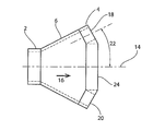
- FIG. 3 is a side view of a “duckbill” type check valve nozzle having two discharge ports at an outward angle to the longitudinal centerline of the check valve nozzle and one discharge port at a 0 degree angle to the longitudinal centerline of the check valve nozzle.
- FIG. 4 is a side view of a “duckbill” type check valve nozzle having two discharge ports at an inward angle to the longitudinal centerline of the check valve nozzle and one discharge port at a 0 degree angle to the longitudinal centerline of the check valve nozzle.
- FIG. 5A is a top view of a three lipped “duckbill” type check valve nozzle having four discharge ports.
- FIG. 5B is an end view of a partially open three lipped “duckbill” type check valve nozzle having four discharge ports.
- FIG. 5C is an end view of a fully open three lipped “duckbill” type check valve nozzle having four discharge ports.
- FIG. 6 is a top view of a three lipped “duckbill” type check valve nozzle having three discharge ports at an outward angle to the longitudinal centerline of the check valve nozzle and one discharge port at a 0 degree angle to the longitudinal centerline of the check valve nozzle.
- FIG. 7 is a top view of a three lipped “duckbill” type check valve nozzle having three discharge ports at an inward angle to the longitudinal centerline of the check valve nozzle and one discharge port at a 0 degree angle to the longitudinal centerline of the check valve nozzle.
- FIG. 8A is a side view of a “duckbill” type check valve nozzle having two fixed discharge ports and one discharge port that changes size and shape as fluid flows through it.
- FIG. 8B is an end view of a partially open “duckbill” type check valve nozzle having two fixed discharge ports and one discharge port that changes size and shape as fluid flows through it.
- FIG. 8C is an end view of a fully open “duckbill” type check valve nozzle having two fixed discharge ports and one discharge port that changes size and shape as fluid flows through it.
- FIG. 9 is a side view of a “duckbill” type check valve nozzle having three discharge ports and two inlet ports.
- FIG. 10A is a side view of a fully closed circular “pancake” type check valve nozzle having two discharge ports.
- FIG. 10B is a side view of a fully open circular “pancake” type check valve nozzle having two discharge ports.
- FIG. 10C is a top view of the back plate of a circular “pancake” type check valve nozzle having two discharge ports showing the areas where the front plate is attached to the top face of the back plate.
- FIG. 11 is a top view of the back plate of an octagonal “pancake” type check valve nozzle having four discharge ports showing the areas where the front plate is attached to the top face of the back plate.
- FIG. 12A is a side view of a fully closed circular “pancake” type check valve nozzle having a convex shape to direct the fluid in a forward direction.
- FIG. 12B is a side view of a fully open circular “pancake” type check valve nozzle having a convex shape to direct the fluid in a forward direction.
- FIG. 13A is a side view of a fully closed circular “pancake” type check valve nozzle having two discharge ports and a concave shape to direct the fluid in a rearward direction.
- FIG. 13B is a side view of a fully open circular “pancake” type check valve nozzle having two discharge ports and a concave shape to direct the fluid in a rearward direction.
- FIG. 14A is a side view of a check valve nozzle assembly having four discharge outlets and four check valve nozzles oriented at different angles to the longitudinal end cap centerline.
- FIG. 14B is an end view of a partially open check valve nozzle assembly having four discharge outlets and four check valve nozzles oriented at different angles to the longitudinal end cap centerline.
- FIG. 14C is an end view of a fully open check valve nozzle assembly having four discharge outlets and four check valve nozzles oriented at different angles to the longitudinal end cap centerline.
- FIG. 15A is a side view of one embodiment of the inventive check valve nozzle clamped to the discharge end of a conduit.
- FIG. 15B is a side view of one embodiment of the inventive check valve nozzle attached to the discharge end of a conduit using mating flanges.
- FIG. 15C is a perspective view of one embodiment of the inventive check valve nozzle attached to the outer circumference of a conduit.
- FIG. 15D is a cross-sectional view of one embodiment of the inventive check valve nozzle attached to the interior of the conduit around the circumference.
- the present invention seeks to provide a check valve nozzle that provides efficient mixing of the fluid being discharged from the check valve nozzle and the receiving fluid.
- the check valve nozzle has an upstream inlet portion 2 that is mountable on a discharge conduit, a downstream outlet portion 4 , and a transition portion 6 that extends between the inlet portion 2 and the outlet portion 4 .
- the outlet portion 4 contains three discharge ports 8 , 10 , 12 that provide for three separate streams of discharge fluid from the check valve nozzle.
- the discharge ports change size and shape as fluid is discharged through them and are adapted to prevent backflow of the receiving fluid from entering the check valve nozzle. All of the discharge ports 8 , 10 , 12 are oriented at a 0 degree angle to the longitudinal centerline 14 of the check valve nozzle. Having three streams increases the surface area of the discharged fluid and enhances mixing efficiency with the receiving fluid.
- the primary flow 16 through the check valve nozzle is parallel to the longitudinal centerline 14 of the check valve nozzle.
- the headloss (pressure drop) as the fluid flows through the check valve nozzle has a linear relationship with the flow rate of the fluid passing through the check valve nozzle. This provides improved mixing over a fixed orifice nozzle where there is a “square law” relationship between headloss and flow rate.
- any number of discharge ports may be employed as long as there are at least two.
- the discharge ports may be in the outlet portion 4 , the transition portion 6 , or both. See FIGS. 2A and 2B .
- FIGS. 1A-1C two of the discharge ports are shown as being the same size and as being smaller than the third discharge port.
- the discharge ports may be any combination of sizes. They can all be the same size, they can all be different sizes, or any combination thereof.
- the discharge ports may be made of an elastomeric material or a reinforced elastomeric material. Suitable elastomeric materials include Neoprene®, natural or synthetic “Gum Rubber,” Viton®, and similar materials. Suitable reinforcement includes nylon, polyester, Kevlar®, or similar material.
- the discharge ports may be made of the same or different materials from one another. By changing the elastomer, the wall thickness, or the size, location, and arrangement of reinforcing plies, each exit port can be made to a different stiffness to provide different flow characteristics to each.
- FIG. 3 shows an alternative configuration of the first embodiment.
- Two of the three discharge ports 18 , 20 are shown placed at an outward angle 22 from the longitudinal centerline 14 of the check valve nozzle. This directs the flow from these two ports in a direction away from the primary flow 16 while the flow through discharge port 24 , which is at a 0 degree angle to the longitudinal centerline 14 , remains directed in the direction of the primary flow 16 .
- This configuration has advantages in situations where the receiving fluid is contained in a relatively small enclosure, such as a potable water tank, where the discharge from the angled discharge ports 18 , 20 can be redirected off the sidewalls of the containment vessel to increase turbulence and improve mixing.
- FIG. 3 shows two ports 18 , 20 oriented at the same outward angle 22 and one port 24 remaining oriented in the direction of primary flow 16
- any of the discharge ports may be oriented at any outward angle from the longitudinal centerline 14 .
- some discharge ports can be at the same angle or all of the discharge ports can be at different angles.
- the discharge ports may be oriented at an outward angle greater than 0 degrees and less than 180 degrees.
- FIG. 4 shows a check valve nozzle similar to the one shown in FIG. 3 except that two of the three discharge ports 26 , 28 are shown placed at an inward angle 30 from the longitudinal centerline 14 of the check valve nozzle. This directs the flow from these two ports in a direction into the primary flow while the flow through discharge port 32 , which is at a 0 degree angle to the longitudinal centerline 14 , remains directed in the direction of the primary flow 16 .
- This configuration has advantages where the receiving body of fluid is contained in a long but relatively small diameter enclosure such as a pipe. The flow from discharge ports 26 , 28 impinges on the flow from discharge port 32 creating increased turbulence and improved mixing.
- FIG. 4 shows two ports 26 , 28 oriented at the same inward angle 30 and one port 32 remaining oriented in the direction of primary flow 16
- any of the discharge ports may be oriented at any inward angle from the longitudinal centerline 14 .
- some discharge ports can be at the same angle, or all of the discharge ports can be at different angles.
- the discharge ports may be oriented at an inward angle greater than 0 degrees and less than 90 degrees.
- any discharge port may be placed at either an outward angle, an inward angle, or a 0 degree angle to the longitudinal centerline 14 .
- all discharge ports may be oriented in an outward direction, all of the discharge ports may be oriented in an inward direction, all discharge ports may be oriented at a 0 degree angle to the longitudinal centerline 14 , or any combination thereof.
- the ports may vary in size and materials.
- FIGS. 1-4 show a one lipped “duckbill” check valve nozzle
- FIGS. 5A-5C show a three lipped “duckbill” check valve nozzle with all ports 34 at a 0 degree angle to the longitudinal centerline 14
- FIG. 6 shows a three lipped “duckbill” check valve nozzle with three of the four ports (two are shown in FIGS. 6-36, 38 ) at an outward angle 40 to the longitudinal centerline 14
- FIG. 7 shows a three lipped “duckbill” check valve nozzle with three of the four ports (two are shown in FIGS. 7-42, 44 ) at an outward angle 46 to the longitudinal centerline 14 .
- discharge ports in any of the described embodiments may be of fixed size and shape such that the flow of fluid through them does not change their size and shape.
- This configuration may be used where fear of backflow of the receiving fluid into the check valve nozzle is not an issue.
- FIGS. 8A-8C show an example of such a configuration based on the check valve nozzle shown in FIG. 1 .
- Discharge ports 48 , 52 are fixed in size and shape while discharge port 50 changes in size and shape as fluid passes through it.
- FIGS. 8A-8C show merely one embodiment using discharge ports of fixed size and shape. Such fixed discharge ports may be substituted for any discharge ports shown or described above.
- the check valve nozzle may also contain more than one inlet port 53 in the upstream inlet portion to allow more than one fluid stream to be mixed in the valve prior to discharge into and mixing with the receiving fluid.
- a second embodiment of the present invention is a “pancake” type check valve nozzle shown in FIGS. 10A-10C .
- the check valve nozzle has a back plate 54 which is a disc containing a central bore 58 .
- a circular cuff 60 is attached to the bottom face 62 of the back plate 54 .
- the cuff 60 has a flange 64 and an inlet conduit 66 .
- the flange 64 is attached to one end of the inlet conduit 66 and extends away from the sidewalls of the inlet conduit 66 .
- the other end of the inlet conduit 66 is mountable on a discharge conduit.
- the flange 64 of the cuff 60 is attached around its entire periphery to the bottom face 62 of the back plate 54 to form a leak proof seal.
- the flange 64 of the cuff 60 may also be molded or fabricated as an integral part of the back plate 54 .
- a circular front plate 68 is preferably the same size as the back plate 54 and is attached to the top face 70 of the back plate 54 in at least two locations 71 near the periphery of the back plate 54 , leaving at least two areas where the front plate 68 is not attached to the back plate 54 .
- Discharge outlets 72 are formed where the front plate 68 is not attached to the back plate 54 .
- FIG. 10C shows a top view of a check valve nozzle with two attachment points 71 creating two discharge openings 72 .
- At least one of the front plate 68 or the back plate 54 is constructed of flexible material, for example, low durometer elastomer (e.g., 35 on the Shore A scale) with or without reinforcement such as fabric or mesh.
- the fluid flows through the inlet conduit 66 of the cuff 60 , through the central bore 58 of the back plate 54 and the fluid pressure causes the front plate 68 and/or back plate 54 to flex, allowing the fluid to be discharged from the two discharge ports 72 created where the front plate 68 is not attached to the back plate 54 .
- the flow is redirected at a 90 degree angle from the direction of the primary flow 74 through the inlet conduit 66 of the cuff 60 .
- the cuff may be constructed of rigid material such as high durometer elastomer (e.g., 90 on the Shore A scale), plastic, metal, or other suitable rigid material or a flexible material such as low durometer elastomer (e.g., 35 on the Shore A scale) with or without reinforcement such as fabric or mesh.
- rigid material such as high durometer elastomer (e.g., 90 on the Shore A scale), plastic, metal, or other suitable rigid material or a flexible material such as low durometer elastomer (e.g., 35 on the Shore A scale) with or without reinforcement such as fabric or mesh.
- FIG. 11 shows an octagonal “pancake” type check valve nozzle with four attachment points 71 resulting in four discharge ports 72 .
- the back plate, cuff, and front plate need not be circular and may be of any geometry including oval, elliptical, trapezoidal, rectangular, polygonal, or any other suitable shape. It is preferred that the back plate, cuff, and front plate are all of the same geometry. As an example, a “pancake” type check valve nozzle with an octagonal geometry and four discharge ports 72 is shown in FIG. 11 .
- the “pancake” type check valve nozzle can also be constructed to direct flow in a generally forward direction more in line with the primary flow 74 . As shown in FIGS. 12A and 12B , to cause the flow from the discharge ports 72 to be in the generally forward direction, the back plate 54 , cuff 60 , and front plate 68 are convex with respect to the primary flow 74 .
- the “pancake” type check valve nozzle can also be constructed to direct flow in a generally rearward direction, more in the direction opposite to the direction of the primary flow 74 . As shown in FIGS. 13A and 13B , to cause the flow from the discharge ports 72 to be in the generally rearward direction, the back plate 54 , cuff 60 , and front plate 68 are concave with respect to the primary flow 74 .
- a third embodiment of the present invention is a check valve nozzle assembly shown in FIGS. 14A-14C .
- the check valve nozzle assembly has an end cap 75 mountable on the discharge end of a conduit.
- the end cap 75 has an upstream inlet portion 76 that is mountable on a discharge conduit and a downstream outlet portion 78 .
- the outlet portion 78 contains at least two discharge outlets 80 .
- Check valve nozzles 82 comprising an upstream inlet 84 , a downstream outlet portion 86 , and a transition portion 88 between the upstream inlet 84 and the downstream outlet portion 86 are attached to the end cap 75 .
- the inlet 84 of the check valve nozzle 82 is attached to the discharge outlet 80 in the outlet portion 78 of the end cap 75 .
- Each discharge outlet 80 is provided with a check valve nozzle 82 .
- the check valve nozzles 82 can be either separately attached to the end cap 75 by suitable means such as adhesive bonding or clamping or molded or fabricated as an integral part of the end cap 75 .
- the check valve nozzles are adapted to prevent backflow of the receiving fluid from entering the check valve nozzle assembly.
- the check valve nozzles 82 are oriented at different angles to the end cap centerline 90 . This directs the flow from each check valve nozzle in a different direction, increasing the mixing efficiency of the check valve nozzle assembly.
- the primary flow 92 through the check valve nozzle assembly is parallel to the longitudinal centerline 90 of the end cap 75 .
- the headloss (pressure drop) as the fluid flows through the multiple check valve nozzles 82 has a linear relationship with the flow rate of the fluid passing through the check valve nozzles 82 . This provides improved mixing over a fixed orifice nozzle where there is a “square law” relationship between headloss and flow rate.
- check valve nozzles While four check valve nozzles are shown in FIGS. 14B-14C , any number of check valve nozzles may be employed as long as there are at least two. In FIGS. 14A-14C , all of the check valve nozzles are shown as being the same size. However, the check valve nozzles may be any combination of sizes. They can all be the same size, they can all be different sizes, or any combination thereof.
- the check valve nozzles may be made of an elastomeric material or a reinforced elastomeric material. Suitable elastomeric materials include Neoprene®, natural or synthetic “Gum Rubber,” Viton®, and similar materials. Suitable reinforcement includes nylon, polyester, Kevlar®, or similar material.
- the check valve nozzles may be made of the same or different materials from one another. By changing the elastomer, the wall thickness, or the size, location, and arrangement of reinforcing plies, each exit port can be made to a different stiffness to provide different flow characteristics to each.
- the check valve nozzles 82 may be of any of the “duckbill” type check valve nozzles previously described as one embodiment of the present invention.
- the check valve nozzles 82 while shown in FIGS. 14A-14C oriented at different angles to the longitudinal centerline 90 of the end cap 75 , may be oriented at any angle with respect to the longitudinal centerline 90 of the end cap 75 and each other. They may all be at the same angle, all at different angles, or any combination thereof.
- one or more of the discharge outlets may be left open by not attaching a check valve nozzle.
- any of the embodiments described herein may be mounted to a discharge end of a conduit having any shape including but not limited to circular and elliptical. This mounting may be accomplished by any suitable means.
- the check valve nozzle inlet portion 94 may be slipped over the discharge end of the conduit 96 and secured with a clamp 98 as shown in FIG. 15A .
- the check valve nozzle may be provided with a flange 100 on the inlet portion 94 that is secured to a mating flange 102 on the discharge end of the conduit 96 with suitable fasteners 104 as shown in FIG. 15B .
- Suitable flanges include but are not limited to ANSI 125# flanges and 4-hole flanges.
- the check valve nozzle may be provided with a flange 106 on the inlet portion 94 that is secured to the circumference of a conduit 108 using suitable fasteners 110 such that it directs flow 112 at an outward angle to the primary flow 114 through the conduit 108 .
- the inlet portion 94 of the check valve nozzle may be secured around the interior circumference of a conduit 108 using an internal clamp 116 .
Landscapes
- Engineering & Computer Science (AREA)
- General Engineering & Computer Science (AREA)
- Mechanical Engineering (AREA)
- Check Valves (AREA)
Abstract
Description
Claims (6)
Priority Applications (1)
| Application Number | Priority Date | Filing Date | Title |
|---|---|---|---|
| US13/409,936 US10316977B2 (en) | 2011-03-01 | 2012-03-01 | Multi-outlet check valve nozzle |
Applications Claiming Priority (2)
| Application Number | Priority Date | Filing Date | Title |
|---|---|---|---|
| US201161447911P | 2011-03-01 | 2011-03-01 | |
| US13/409,936 US10316977B2 (en) | 2011-03-01 | 2012-03-01 | Multi-outlet check valve nozzle |
Publications (2)
| Publication Number | Publication Date |
|---|---|
| US20120247595A1 US20120247595A1 (en) | 2012-10-04 |
| US10316977B2 true US10316977B2 (en) | 2019-06-11 |
Family
ID=46925662
Family Applications (1)
| Application Number | Title | Priority Date | Filing Date |
|---|---|---|---|
| US13/409,936 Active 2032-09-07 US10316977B2 (en) | 2011-03-01 | 2012-03-01 | Multi-outlet check valve nozzle |
Country Status (2)
| Country | Link |
|---|---|
| US (1) | US10316977B2 (en) |
| CA (1) | CA2769897C (en) |
Cited By (3)
| Publication number | Priority date | Publication date | Assignee | Title |
|---|---|---|---|---|
| USD886236S1 (en) | 2018-05-16 | 2020-06-02 | Bradley Fixtures Corporation | Housing for multiple valves |
| US11060628B2 (en) | 2018-05-16 | 2021-07-13 | Bradley Fixtures Corporation | Housing for multiple mixing valves |
| USD951403S1 (en) | 2019-12-04 | 2022-05-10 | Sloan Valve Company | Valve |
Families Citing this family (8)
| Publication number | Priority date | Publication date | Assignee | Title |
|---|---|---|---|---|
| US9062879B2 (en) * | 2011-08-31 | 2015-06-23 | Beckett Gas, Inc. | Inshot gas burner |
| EP2745943B1 (en) * | 2012-12-20 | 2017-11-01 | Collomix Rühr-und Mischgeräte GmbH | Metering device for the metered dispensing of flowable media |
| US9085065B2 (en) | 2013-02-28 | 2015-07-21 | Comco Inc. | Particulate media conveying systems and apparatuses |
| US20150308582A1 (en) * | 2014-04-23 | 2015-10-29 | W. L. Gore & Associates, Inc. | Venting Systems and Methods |
| US9950491B2 (en) | 2014-04-04 | 2018-04-24 | Pregis Innovative Packaging Llc | Flexible nozzle for inflation and sealing device |
| US10001787B2 (en) * | 2014-06-02 | 2018-06-19 | Aqseptence Group, Inc. | Controller for vacuum sewage system |
| KR101863427B1 (en) * | 2016-02-02 | 2018-06-01 | 한국수력원자력 주식회사 | Gas Collection Device for Trapping Accumulation Gas in Pipes |
| USD888102S1 (en) * | 2018-06-19 | 2020-06-23 | Curtis O'Hare | Flat air manifold and connector |
Citations (25)
| Publication number | Priority date | Publication date | Assignee | Title |
|---|---|---|---|---|
| US795310A (en) * | 1904-08-30 | 1905-07-25 | John Rogers | Fire-extinguisher. |
| US2261500A (en) * | 1939-02-11 | 1941-11-04 | Howard B Lewis | Shower head |
| US2392085A (en) * | 1944-07-29 | 1946-01-01 | Clyde B Ferrel | Spray nozzle |
| US2402741A (en) * | 1944-10-03 | 1946-06-25 | Adolphe O Draviner | Spray head |
| US3387624A (en) * | 1962-06-20 | 1968-06-11 | Soucy Wilfred Roland | Automatic valvular closure |
| US3395858A (en) * | 1964-09-21 | 1968-08-06 | Continental Oil Co | One-piece resilient compressor valve |
| US3565106A (en) * | 1968-11-06 | 1971-02-23 | William J Baumbach | Diaphragm for flood and suds control |
| US4642097A (en) * | 1985-03-25 | 1987-02-10 | Siposs George G | Left ventrical vacuum control and pressure relief valve |
| US5074471A (en) * | 1989-03-11 | 1991-12-24 | Swf Auto-Electric Gmbh | Windshield cleaning system |
| WO1996027647A1 (en) * | 1995-03-07 | 1996-09-12 | Shell Internationale Research Maatschappij B.V. | Feed nozzle assembly |
| FR2752755A1 (en) * | 1996-09-05 | 1998-03-06 | Coutier Moulage Gen Ind | Vehicle windscreen washer jet |
| US5730336A (en) * | 1996-01-02 | 1998-03-24 | Cascade Designs, Inc. | Dispensing valve for a flexible liquid container |
| US5924452A (en) * | 1997-09-08 | 1999-07-20 | Baxter International Inc. | Valve assembly |
| US5947390A (en) * | 1997-12-30 | 1999-09-07 | Smith; Gary L | Reduced emissions flow control plate |
| US6138710A (en) * | 1997-12-10 | 2000-10-31 | Playtex Products, Inc. | Vent disc for baby bottle and method and apparatus for manufacture thereof |
| US6367505B1 (en) | 2000-03-22 | 2002-04-09 | Red Valve Co., Inc. | Check valve with oversized bill |
| US6371392B1 (en) * | 2000-06-01 | 2002-04-16 | Lee E. Steinman | Nozzle construction |
| US20030062426A1 (en) * | 2001-09-04 | 2003-04-03 | Gregory George Richard | Shower handset |
| US6739527B1 (en) * | 2003-02-24 | 2004-05-25 | Shong I Copper Co., Ltd. | Shower head assembly |
| US7040554B2 (en) * | 2002-12-20 | 2006-05-09 | Asept International Ab | Spray head |
| US20060118189A1 (en) * | 2004-11-12 | 2006-06-08 | Cook Incorporated | Flow variation valve assembly |
| US7445028B1 (en) * | 2005-09-26 | 2008-11-04 | General Rubber Corporation | Check valves |
| US20090147474A1 (en) * | 2007-12-06 | 2009-06-11 | Hon Hai Precision Industry Co., Ltd. | Apparatus for preventing refluence of air in an electronic device |
| US8621677B2 (en) * | 2009-02-27 | 2014-01-07 | Airbus Operations Gmbh | Odour seal for a vacuum toilet drain system |
| US8668168B1 (en) * | 2011-12-15 | 2014-03-11 | The United States Of America As Represented By The Administrator Of The National Aeronautics And Space Administration | Space vehicle valve system |
-
2012
- 2012-03-01 CA CA2769897A patent/CA2769897C/en active Active
- 2012-03-01 US US13/409,936 patent/US10316977B2/en active Active
Patent Citations (25)
| Publication number | Priority date | Publication date | Assignee | Title |
|---|---|---|---|---|
| US795310A (en) * | 1904-08-30 | 1905-07-25 | John Rogers | Fire-extinguisher. |
| US2261500A (en) * | 1939-02-11 | 1941-11-04 | Howard B Lewis | Shower head |
| US2392085A (en) * | 1944-07-29 | 1946-01-01 | Clyde B Ferrel | Spray nozzle |
| US2402741A (en) * | 1944-10-03 | 1946-06-25 | Adolphe O Draviner | Spray head |
| US3387624A (en) * | 1962-06-20 | 1968-06-11 | Soucy Wilfred Roland | Automatic valvular closure |
| US3395858A (en) * | 1964-09-21 | 1968-08-06 | Continental Oil Co | One-piece resilient compressor valve |
| US3565106A (en) * | 1968-11-06 | 1971-02-23 | William J Baumbach | Diaphragm for flood and suds control |
| US4642097A (en) * | 1985-03-25 | 1987-02-10 | Siposs George G | Left ventrical vacuum control and pressure relief valve |
| US5074471A (en) * | 1989-03-11 | 1991-12-24 | Swf Auto-Electric Gmbh | Windshield cleaning system |
| WO1996027647A1 (en) * | 1995-03-07 | 1996-09-12 | Shell Internationale Research Maatschappij B.V. | Feed nozzle assembly |
| US5730336A (en) * | 1996-01-02 | 1998-03-24 | Cascade Designs, Inc. | Dispensing valve for a flexible liquid container |
| FR2752755A1 (en) * | 1996-09-05 | 1998-03-06 | Coutier Moulage Gen Ind | Vehicle windscreen washer jet |
| US5924452A (en) * | 1997-09-08 | 1999-07-20 | Baxter International Inc. | Valve assembly |
| US6138710A (en) * | 1997-12-10 | 2000-10-31 | Playtex Products, Inc. | Vent disc for baby bottle and method and apparatus for manufacture thereof |
| US5947390A (en) * | 1997-12-30 | 1999-09-07 | Smith; Gary L | Reduced emissions flow control plate |
| US6367505B1 (en) | 2000-03-22 | 2002-04-09 | Red Valve Co., Inc. | Check valve with oversized bill |
| US6371392B1 (en) * | 2000-06-01 | 2002-04-16 | Lee E. Steinman | Nozzle construction |
| US20030062426A1 (en) * | 2001-09-04 | 2003-04-03 | Gregory George Richard | Shower handset |
| US7040554B2 (en) * | 2002-12-20 | 2006-05-09 | Asept International Ab | Spray head |
| US6739527B1 (en) * | 2003-02-24 | 2004-05-25 | Shong I Copper Co., Ltd. | Shower head assembly |
| US20060118189A1 (en) * | 2004-11-12 | 2006-06-08 | Cook Incorporated | Flow variation valve assembly |
| US7445028B1 (en) * | 2005-09-26 | 2008-11-04 | General Rubber Corporation | Check valves |
| US20090147474A1 (en) * | 2007-12-06 | 2009-06-11 | Hon Hai Precision Industry Co., Ltd. | Apparatus for preventing refluence of air in an electronic device |
| US8621677B2 (en) * | 2009-02-27 | 2014-01-07 | Airbus Operations Gmbh | Odour seal for a vacuum toilet drain system |
| US8668168B1 (en) * | 2011-12-15 | 2014-03-11 | The United States Of America As Represented By The Administrator Of The National Aeronautics And Space Administration | Space vehicle valve system |
Non-Patent Citations (2)
| Title |
|---|
| "Series TFO Flow Restrictor", Red Valve Company, Inc., 1 p., Bulletin #528-91, www.redvalve.com. |
| "Tideflex® Mixing System" catalog, Tideflex® Technologies, Division of Red Valve Company, Inc., 2006, 8 pp., www.tideflex.com. |
Cited By (6)
| Publication number | Priority date | Publication date | Assignee | Title |
|---|---|---|---|---|
| USD886236S1 (en) | 2018-05-16 | 2020-06-02 | Bradley Fixtures Corporation | Housing for multiple valves |
| USD917013S1 (en) | 2018-05-16 | 2021-04-20 | Bradley Fixtures Corporation | Housing for multiple valves |
| US11060628B2 (en) | 2018-05-16 | 2021-07-13 | Bradley Fixtures Corporation | Housing for multiple mixing valves |
| USD958937S1 (en) | 2018-05-16 | 2022-07-26 | Bradley Fixtures Corporation | Housing for multiple valves |
| US11920691B2 (en) | 2018-05-16 | 2024-03-05 | Bradley Fixtures LLC | Housing for multiple mixing valves |
| USD951403S1 (en) | 2019-12-04 | 2022-05-10 | Sloan Valve Company | Valve |
Also Published As
| Publication number | Publication date |
|---|---|
| CA2769897A1 (en) | 2012-09-01 |
| US20120247595A1 (en) | 2012-10-04 |
| CA2769897C (en) | 2021-03-02 |
Similar Documents
| Publication | Publication Date | Title |
|---|---|---|
| US10316977B2 (en) | Multi-outlet check valve nozzle | |
| US6412514B1 (en) | Flip check valve | |
| CA3001867C (en) | Faucet including an open waterway | |
| US3807444A (en) | Check valve | |
| US8608464B2 (en) | Check valve | |
| US8807458B2 (en) | Vortex-generating nozzle-end ring | |
| EP2988856B1 (en) | Fluid flow nozzle | |
| US20040217209A1 (en) | Thin profile multi-function showerhead | |
| CA2384678A1 (en) | Nested duckbill check valves | |
| US9931601B2 (en) | Venturi bypass system and associated methods | |
| NZ516540A (en) | A non-return valve | |
| WO2017057033A1 (en) | Emitter and drip irrigation tube | |
| CA2110015A1 (en) | Wall Water Hydrant Having Backflow and Back Siphonage Preventor | |
| US20080223471A1 (en) | Hose with multiple passages | |
| WO2021186156A3 (en) | A microbubble generator | |
| US9206914B2 (en) | Check valve | |
| US8418994B2 (en) | Hot-cold inlet pipe structure | |
| US8556226B2 (en) | Valve with the device enhancing capability of its closure member and related seat ring to resist erosion | |
| CN109140104A (en) | A kind of engineering plastics flange and its application with clamping structure | |
| CN105927763B (en) | Convergence diverging spout regulating valve | |
| CN210830953U (en) | Anti-drip atomization three-way pipe | |
| JP6837377B2 (en) | Emitter and drip irrigation tubes | |
| US7267477B1 (en) | Fluid blending utilizing either or both passive and active mixing | |
| US11396951B1 (en) | Check valve | |
| JP5452365B2 (en) | strainer |
Legal Events
| Date | Code | Title | Description |
|---|---|---|---|
| AS | Assignment |
Owner name: RED VALVE COMPANY, INC., PENNSYLVANIA Free format text: ASSIGNMENT OF ASSIGNORS INTEREST;ASSIGNORS:RAFTIS, SPIROS G.;DUER, MICHAEL J.;SIGNING DATES FROM 20110304 TO 20110308;REEL/FRAME:028412/0265 |
|
| STPP | Information on status: patent application and granting procedure in general |
Free format text: NOTICE OF ALLOWANCE MAILED -- APPLICATION RECEIVED IN OFFICE OF PUBLICATIONS |
|
| STCF | Information on status: patent grant |
Free format text: PATENTED CASE |
|
| AS | Assignment |
Owner name: BMO HARRIS BANK N.A., AS COLLATERAL AGENT, MINNESOTA Free format text: SECURITY INTEREST;ASSIGNOR:RED VALVE COMPANY, INC.;REEL/FRAME:054800/0407 Effective date: 20201231 |
|
| AS | Assignment |
Owner name: JPMORGAN CHASE BANK, N.A., AS COLLATERAL AGENT, ILLINOIS Free format text: SECURITY INTEREST;ASSIGNORS:DEZURIK, INC.;RED VALVE COMPANY, INC.;REEL/FRAME:059970/0609 Effective date: 20220520 |
|
| FEPP | Fee payment procedure |
Free format text: MAINTENANCE FEE REMINDER MAILED (ORIGINAL EVENT CODE: REM.); ENTITY STATUS OF PATENT OWNER: LARGE ENTITY |
|
| FEPP | Fee payment procedure |
Free format text: SURCHARGE FOR LATE PAYMENT, LARGE ENTITY (ORIGINAL EVENT CODE: M1554); ENTITY STATUS OF PATENT OWNER: LARGE ENTITY |
|
| MAFP | Maintenance fee payment |
Free format text: PAYMENT OF MAINTENANCE FEE, 4TH YEAR, LARGE ENTITY (ORIGINAL EVENT CODE: M1551); ENTITY STATUS OF PATENT OWNER: LARGE ENTITY Year of fee payment: 4 |