US10316874B2 - Cover panel clip - Google Patents
Cover panel clip Download PDFInfo
- Publication number
- US10316874B2 US10316874B2 US15/642,552 US201715642552A US10316874B2 US 10316874 B2 US10316874 B2 US 10316874B2 US 201715642552 A US201715642552 A US 201715642552A US 10316874 B2 US10316874 B2 US 10316874B2
- Authority
- US
- United States
- Prior art keywords
- clip
- protrusion
- endpoint
- compressible
- midpoint
- Prior art date
- Legal status (The legal status is an assumption and is not a legal conclusion. Google has not performed a legal analysis and makes no representation as to the accuracy of the status listed.)
- Active, expires
Links
- 238000000034 method Methods 0.000 claims description 10
- 238000003780 insertion Methods 0.000 claims description 6
- 230000037431 insertion Effects 0.000 claims description 6
- 230000007246 mechanism Effects 0.000 description 40
- 230000006835 compression Effects 0.000 description 7
- 238000007906 compression Methods 0.000 description 7
- 230000008878 coupling Effects 0.000 description 6
- 238000010168 coupling process Methods 0.000 description 6
- 238000005859 coupling reaction Methods 0.000 description 6
- 238000003860 storage Methods 0.000 description 5
- 239000000463 material Substances 0.000 description 3
- 239000004033 plastic Substances 0.000 description 3
- 229920003023 plastic Polymers 0.000 description 3
- 230000008901 benefit Effects 0.000 description 2
- 238000006073 displacement reaction Methods 0.000 description 2
- 230000009977 dual effect Effects 0.000 description 2
- 238000001746 injection moulding Methods 0.000 description 2
- 239000007788 liquid Substances 0.000 description 2
- 239000000088 plastic resin Substances 0.000 description 2
- 238000003825 pressing Methods 0.000 description 2
- XLYOFNOQVPJJNP-UHFFFAOYSA-N water Substances O XLYOFNOQVPJJNP-UHFFFAOYSA-N 0.000 description 2
- 239000004677 Nylon Substances 0.000 description 1
- 239000004699 Ultra-high molecular weight polyethylene Substances 0.000 description 1
- DHKHKXVYLBGOIT-UHFFFAOYSA-N acetaldehyde Diethyl Acetal Natural products CCOC(C)OCC DHKHKXVYLBGOIT-UHFFFAOYSA-N 0.000 description 1
- 125000002777 acetyl group Chemical class [H]C([H])([H])C(*)=O 0.000 description 1
- 238000005516 engineering process Methods 0.000 description 1
- 238000007667 floating Methods 0.000 description 1
- 238000009413 insulation Methods 0.000 description 1
- 238000003698 laser cutting Methods 0.000 description 1
- 238000004519 manufacturing process Methods 0.000 description 1
- 229920001778 nylon Polymers 0.000 description 1
- 239000003208 petroleum Substances 0.000 description 1
- 230000003068 static effect Effects 0.000 description 1
- 239000000126 substance Substances 0.000 description 1
- 229920000785 ultra high molecular weight polyethylene Polymers 0.000 description 1
- 239000002699 waste material Substances 0.000 description 1
Images


Classifications
-
- F—MECHANICAL ENGINEERING; LIGHTING; HEATING; WEAPONS; BLASTING
- F16—ENGINEERING ELEMENTS AND UNITS; GENERAL MEASURES FOR PRODUCING AND MAINTAINING EFFECTIVE FUNCTIONING OF MACHINES OR INSTALLATIONS; THERMAL INSULATION IN GENERAL
- F16B—DEVICES FOR FASTENING OR SECURING CONSTRUCTIONAL ELEMENTS OR MACHINE PARTS TOGETHER, e.g. NAILS, BOLTS, CIRCLIPS, CLAMPS, CLIPS OR WEDGES; JOINTS OR JOINTING
- F16B5/00—Joining sheets or plates, e.g. panels, to one another or to strips or bars parallel to them
- F16B5/06—Joining sheets or plates, e.g. panels, to one another or to strips or bars parallel to them by means of clamps or clips
- F16B5/0607—Joining sheets or plates, e.g. panels, to one another or to strips or bars parallel to them by means of clamps or clips joining sheets or plates to each other
- F16B5/0621—Joining sheets or plates, e.g. panels, to one another or to strips or bars parallel to them by means of clamps or clips joining sheets or plates to each other in parallel relationship
-
- B—PERFORMING OPERATIONS; TRANSPORTING
- B65—CONVEYING; PACKING; STORING; HANDLING THIN OR FILAMENTARY MATERIAL
- B65D—CONTAINERS FOR STORAGE OR TRANSPORT OF ARTICLES OR MATERIALS, e.g. BAGS, BARRELS, BOTTLES, BOXES, CANS, CARTONS, CRATES, DRUMS, JARS, TANKS, HOPPERS, FORWARDING CONTAINERS; ACCESSORIES, CLOSURES, OR FITTINGS THEREFOR; PACKAGING ELEMENTS; PACKAGES
- B65D88/00—Large containers
- B65D88/34—Large containers having floating covers, e.g. floating roofs or blankets
- B65D88/36—Large containers having floating covers, e.g. floating roofs or blankets with relatively movable sections
-
- F—MECHANICAL ENGINEERING; LIGHTING; HEATING; WEAPONS; BLASTING
- F16—ENGINEERING ELEMENTS AND UNITS; GENERAL MEASURES FOR PRODUCING AND MAINTAINING EFFECTIVE FUNCTIONING OF MACHINES OR INSTALLATIONS; THERMAL INSULATION IN GENERAL
- F16B—DEVICES FOR FASTENING OR SECURING CONSTRUCTIONAL ELEMENTS OR MACHINE PARTS TOGETHER, e.g. NAILS, BOLTS, CIRCLIPS, CLAMPS, CLIPS OR WEDGES; JOINTS OR JOINTING
- F16B2/00—Friction-grip releasable fastenings
- F16B2/20—Clips, i.e. with gripping action effected solely by the inherent resistance to deformation of the material of the fastening
- F16B2/22—Clips, i.e. with gripping action effected solely by the inherent resistance to deformation of the material of the fastening of resilient material, e.g. rubbery material
-
- Y—GENERAL TAGGING OF NEW TECHNOLOGICAL DEVELOPMENTS; GENERAL TAGGING OF CROSS-SECTIONAL TECHNOLOGIES SPANNING OVER SEVERAL SECTIONS OF THE IPC; TECHNICAL SUBJECTS COVERED BY FORMER USPC CROSS-REFERENCE ART COLLECTIONS [XRACs] AND DIGESTS
- Y10—TECHNICAL SUBJECTS COVERED BY FORMER USPC
- Y10T—TECHNICAL SUBJECTS COVERED BY FORMER US CLASSIFICATION
- Y10T24/00—Buckles, buttons, clasps, etc.
- Y10T24/39—Cord and rope holders
- Y10T24/3916—One-piece
- Y10T24/3924—Sheet material
-
- Y—GENERAL TAGGING OF NEW TECHNOLOGICAL DEVELOPMENTS; GENERAL TAGGING OF CROSS-SECTIONAL TECHNOLOGIES SPANNING OVER SEVERAL SECTIONS OF THE IPC; TECHNICAL SUBJECTS COVERED BY FORMER USPC CROSS-REFERENCE ART COLLECTIONS [XRACs] AND DIGESTS
- Y10—TECHNICAL SUBJECTS COVERED BY FORMER USPC
- Y10T—TECHNICAL SUBJECTS COVERED BY FORMER US CLASSIFICATION
- Y10T24/00—Buckles, buttons, clasps, etc.
- Y10T24/44—Clasp, clip, support-clamp, or required component thereof
- Y10T24/44641—Clasp, clip, support-clamp, or required component thereof having gripping member formed from, biased by, or mounted on resilient member
- Y10T24/44932—Clasp, clip, support-clamp, or required component thereof having gripping member formed from, biased by, or mounted on resilient member having specific surface material or irregularity on or along engaging face
-
- Y—GENERAL TAGGING OF NEW TECHNOLOGICAL DEVELOPMENTS; GENERAL TAGGING OF CROSS-SECTIONAL TECHNOLOGIES SPANNING OVER SEVERAL SECTIONS OF THE IPC; TECHNICAL SUBJECTS COVERED BY FORMER USPC CROSS-REFERENCE ART COLLECTIONS [XRACs] AND DIGESTS
- Y10—TECHNICAL SUBJECTS COVERED BY FORMER USPC
- Y10T—TECHNICAL SUBJECTS COVERED BY FORMER US CLASSIFICATION
- Y10T29/00—Metal working
- Y10T29/49—Method of mechanical manufacture
- Y10T29/49826—Assembling or joining
- Y10T29/49945—Assembling or joining by driven force fit
Definitions
- containment structures such as those commonly used to store quantities of petroleum, waste, water, etc.
- containment structure covers can be single panel structures or multi-panel structures.
- Some systems including multi-panel structures require precise positioning of individual panels relative to one another to achieve a desired coverage.
- Individual panels can be large, difficult to position within a storage tank, prone to shifting, and vulnerable to displacement by wind.
- a clip includes two compressible legs adjoining opposite ends of a central portion partially-enclosing an internal space.
- the clip further includes a clasp with first and second securing tabs. When engaged, the clasp fixedly secures an object within the internal space and supplies an outward force on the compressible legs.
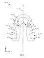
- FIG. 1 illustrates an example clip for securing one or more cover panels within a containment structure cover system.
- FIG. 2 illustrates an example clip under an applied force prior to insertion of the clip into a cover panel of a containment structure cover system.
- FIG. 3 illustrates dual positions of a cable relative to an example clip for securing one or more cover panels within a containment structure cover system.
- FIG. 4 illustrates a cable engaging a clasping mechanism of an example clip to secure legs of the clip within two stacked cover panels of a containment structure cover system.
- FIG. 5 illustrates an example containment structure cover system including a clip that securely fastens one or more cover panels to a cable at an attachment point.
- FIG. 6 illustrates a bottom view of a containment structure cover system including an example clip with compressible legs secured to an attachment point of a cover panel.
- FIG. 7 illustrates another example clip for securing one or more cover panels of a containment structure cover system.
- FIG. 8 illustrates example operations for securing cover panels in an example cover system.
- FIG. 1 illustrates an example clip 100 for securing one or more cover panels within a containment structure cover system.
- the cover clip 100 has a central portion 104 with opposite ends that respectively adjoin one of two compressible legs 106 and 107 .
- the compressible legs 106 and 107 are substantially parallel (e.g., within +/ ⁇ 5 degrees) of one another.
- an elongated object e.g., a cable, rope, rod, bungee, wire, strap, webbing, etc.
- the compressible legs 106 and 107 of the clip 100 are inserted, under a compression force, through an aperture forming an attachment point in another object.
- the following description details various features of the clip 100 that provide for secure coupling of the clip 100 to the attachment point.
- the central portion 104 defines an internal space 110 and is shown to have an annular shape; however, a variety of a shapes are contemplated for such purpose including for example, rectangular, triangular, parabolic, non-traditional shape, etc.
- Each of the compressible legs 106 and 107 of the clip 100 includes a latching mechanism (e.g., latching mechanisms 116 and 117 , respectively) on an outward-facing surface.
- latching mechanism e.g., latching mechanisms 116 and 117 , respectively
- outward-facing surface of a clip refers to a surface facing away from a center longitudinal axis L 1 of the clip (e.g., the clip 100 ).
- an outward-facing surface of the compressible leg 106 is the surface that faces away from the opposing compressible leg 107 .
- Each of the latching mechanisms 116 , 117 includes an endpoint protrusion (e.g., endpoint protrusions 126 , 127 ) and a midpoint protrusion (e.g., midpoint protrusions 128 , 129 ) separated by a distance along a length of a corresponding compressible leg 106 or 107 .
- the latching mechanisms 116 and 117 provide resistance to vertical (e.g., z-direction) motion of an object positioned to encircle the compressible legs 106 and 107 .
- the clip 100 further includes a clasping mechanism 114 configured to fixedly secure an object such as a cable, wire, rope, etc. into a position within the internal space 110 .
- a clasping mechanism 114 configured to fixedly secure an object such as a cable, wire, rope, etc. into a position within the internal space 110 .
- fixedly securing an object means that the object cannot readily move from a secured position.
- a variety of types of clasping mechanisms may be suitable for use in various implementations; however, the clasping mechanism 114 includes a first securing tab 108 and a second securing tab 109 protruding from opposite sides of a neck portion 112 of the clip 100 and into the internal space 110 .
- Each of the first securing tab 108 and the second securing tab 109 includes a first portion (e.g., a first portion 122 ) and a second portion (e.g., a second portion 124 ).
- the first portion 122 adjoins the neck portion 112 of the clip 100 at a first end and connects, at an opposite end, to the second portion 124 .
- the second portion 124 is angled relative to the corresponding first portion 122 so that a free end of the second portion 124 points away from a longitudinal axis L 1 of the clip 100 .
- the clasping mechanism 114 can be engaged to fixedly secure an elongated object (e.g., a cable) and incidentally apply an outward force on the compressible legs 106 and 107 .
- an “outward force” is a force that is directionally away from and substantially perpendicular to the longitudinal axis L 1 of a clip (e.g., the clip 100 ).
- the outward force applied via engagement of the clasping mechanism 114 tightens a coupling between the clip 100 and an adjacent object encircling the compressible legs 106 and 107 .
- the clip 100 may include features in addition to or in lieu of one or more features illustrated in FIG. 1 .
- the latching mechanisms 116 and 117 do not include the midpoint protrusions (e.g., the midpoint protrusions 128 , 129 ). Still other implementations do not include the clasping mechanism 114 .
- FIG. 2 illustrates an example clip 200 under an applied compression force (e.g., a net force of F 1 and F 2 ) prior to insertion into a cover panel (not shown) of a containment structure cover system.
- the clip 200 includes compressible legs 206 and 207 that each adjoins to opposite ends of a central portion 204 .
- the central portion 204 defines an internal space 210 sized to receive an elongated object, such as a cable.
- Each of the compressible legs 206 and 207 of the clip 200 further includes a latching mechanism (e.g., latching mechanisms 216 and 217 ) on an outward-facing surface.
- the latching mechanisms 216 and 217 each include a midpoint protrusion 228 or 229 and an endpoint protrusion 226 or 227 .
- the midpoint protrusions 228 and 229 and endpoint protrusions 226 and 227 are shown slightly curved so as to “hook” over an edge of an adjacent object.
- one or both of the midpoint protrusions 228 , 229 and the endpoint protrusions 226 , 227 are substantially flat (e.g., in the x-direction), or angled in the x-z plane rather than curved.
- Each midpoint protrusion is separated from a corresponding endpoint protrusion by a distance ‘D’ along a length of a corresponding compressible leg 206 or 207 .
- the distance “D” is about or slightly greater than about 0.5 inches. Depending on the desired application of the clip 200 , a variety of other lengths are also contemplated.
- the x-direction length “L” of each of the endpoint protrusions 226 and 227 is greater than an x-direction length of the midpoint protrusions 228 and 229 .
- Longer endpoint protrusions 226 and 227 help to stabilize and fixedly secure the clip 200 to an object encircling the clip 200 (as discussed in greater detail below).
- the x-direction length L of the endpoint protrusions 226 and 227 is about 1 ⁇ 2′′. In another implementation, the x-direction length L is 3 ⁇ 8′′.
- a user can apply the compression force (e.g., F 1 and F 2 ) to bend the compressible legs 206 and 207 toward one another, as shown. While such force is applied, the compressible legs 206 and 207 can be inserted into a receiving aperture, such as a ring or grommet.
- the receiving aperture may have a diameter slightly less than the x-direction width of the compressible legs 206 and 207 when under compressive stress (as shown). In such case, the compressible legs 206 and 207 can be inserted into the receiving aperture while rotated at a slight angle.
- a clasping mechanism 214 can be engaged fixedly attach the clip 200 to another item (not shown).
- FIG. 3 illustrates a cross-sectional view of a system 300 including an elongated object (e.g., a cable 334 ) threaded through an internal space 310 partially-enclosed by a clip 302 .
- the cable 334 is shown in dual positions “A” and “B” within the clip 302 .
- the position “B” represents a fixedly secure position.
- the clip 302 includes compressible legs 306 and 307 inserted into an aperture of an attachment point 340 .
- the attachment point 340 includes two stacked grommets 330 and 332 , each embedded within a respective cover panel 336 or 338 .
- the attachment point 340 includes an aperture formed through a single cover panel (e.g., a single grommet); in yet another implementation the relative dimensions of the clip 302 and attachment point 340 are different than those illustrated in FIG. 3 , and the attachment point 340 includes an aperture formed through three or more cover panels (e.g., an aperture formed by three or more stacked grommets).
- the compressible legs 306 and 307 of the clip 302 adjoin opposite ends of a central portion 304 and each includes a latching mechanism (e.g., latching mechanisms 316 and 317 ).
- a latching mechanism e.g., latching mechanisms 316 and 317 .
- the clip 302 further includes a clasping mechanism 314 that can be engaged to provide a static resistance to compression of the compressible legs 306 and 307 .
- a cover panel or multiple joined cover panels e.g., the cover panels 336 and 338
- the differential lateral force may, in some circumstances, dislodge the clip 302 from the attachment point 340 and compromise system integrity.
- the clasping mechanism 314 can be engaged to provide a compression resistant force that prevents the compressible legs 306 and 307 from collapsing under these opposing lateral forces.
- the cable 334 is threaded through the internal space 310 , as shown at position ‘A’.
- a force is applied to reposition the cable 334 from the position A to the position B between securing tabs of the clasping mechanism 314 .
- the cable 334 supplies an outward force on the compressible legs 306 and 307 , effectively pressing the latching mechanisms 316 and 317 outward against the grommets 330 and 332 .
- This outward force tightens a coupling between the clip 302 and the grommets 330 and 332 , preventing the compressible legs 306 and 307 from decoupling from the grommets 330 and 332 .
- the illustrated coupling between the grommets 330 and 332 and the clip 302 is capable of withstanding up to 200 pounds of sheer force.
- the clip 302 can be manufactured from a variety of suitable flexible materials that are bendable under a compressive force applied by squeezing the compressible legs 306 and 307 toward one another. Suitable flexible materials are sufficiently resistant to deformation so as to resume an original shape when the compressive force is removed.
- the magnitude of force sufficient to bend the compressible legs 306 and 307 may vary.
- the cover clip 302 is flexible enough that it can be deformed by a human hand squeezing the compressible legs 306 and 307 toward once another. When the squeeze is released the clip 302 resumes its original shape.
- Suitable flexible materials for the clip 302 include without limitation Nylon plastic, ultra high molecular weight polyethylene plastic and Acetal plastic.
- the clip 302 may be of a variety of different sizes.
- a diameter of the internal space 310 is larger than a diameter of the cable 334 .
- the cable 334 is 3 ⁇ 8′′ in diameter.
- the clip 302 has an x-direction length of approximately 1.5 inches and a z-direction height of approximately 1 and 3 ⁇ 4 inches.
- the clasping mechanism 314 of the clip 302 is engaged by a peg or ring rather than the cable 334 .
- the compressible legs 306 and 307 of the clip 302 may be inserted through one or more grommets (as shown) and a peg or ring may be inserted between the securing tabs of the clasping mechanism 314 , effectively locking the clip 302 into place.
- the clip 302 can be made using a variety of techniques, including injection molding and laser cutting.
- the clip 302 is manufactured via an injection molding process using a molten plastic resin that is pressurized into die cavities matching the shape of the finished clip 334 (e.g., as pictured).
- the clip 302 is laser cut from plastic resin sheets (e.g., ⁇ 1 ⁇ 4-inch thick) using a computer numeric controlled laser. A variety of other manufacturing techniques are also contemplated.
- FIG. 4 illustrates a cross-sectional view of a portion of a system 400 including a clip 402 secured to stacked cover panels 436 and 438 .
- the clip 402 includes compressible legs 406 and 407 threaded through an aperture formed by two stacked grommets 430 and 432 .
- Each of the grommets 430 and 432 is embedded within one of the cover panels 436 and 438 .
- the clip 402 includes compressible legs 406 and 407 that each adjoins opposite ends of a central portion 404 . Further, the compressible legs 406 and 407 include a latching mechanism (e.g., latching mechanisms 416 and 417 , respectively) on an outward-facing surface of the clip 402 . Each latching mechanism further includes an endpoint protrusion (e.g., an endpoint protrusion 426 ) and a midpoint protrusion (e.g., a midpoint protrusion 428 ) separated by a distance along a length of the corresponding compressible leg 406 or 407 .
- a latching mechanism e.g., latching mechanisms 416 and 417 , respectively
- the clip 402 further includes a clasping mechanism 414 having a pair of securing tabs sized and separated so as to receive a cable 434 in space between them.
- a clasping mechanism 414 having a pair of securing tabs sized and separated so as to receive a cable 434 in space between them.
- the cable 434 supplies an outward force against the compressible legs 406 and 407 , effectively pressing the latching mechanisms 416 and 417 outward against an interior lip of the grommets 430 and 432 .
- This outward force tightens a coupling between the clip 402 and the grommets 430 and 432 , significantly increasing the magnitude of force needed to disengage the grommets 430 or 432 from the compressible legs 406 and 407 .
- the containment structure cover system 400 includes multiple panels designed to float or rest atop a volume within a containment structure.
- the panels are positioned within the containment structure such that a number of attachment points (e.g., such as the attachment point 440 ) are positioned to encircle a common axis.
- a number of clips, such as the clip 402 are securely fastened at each of the attachment points in a manner the same or substantially similar to that illustrated in FIGS. 3 and 4 .
- the cable 434 is threaded through each of the clips (e.g., as shown), and positioned to engage a clasping mechanism (e.g., the clasping mechanism 414 ) of each of the clips. In this manner, panels associated with each attachment point are prevented from shifting relative to one another, and the cable 434 is also locked into a stationary position relative to each cover panel.
- FIG. 5 illustrates a portion of an example containment structure cover system 500 including a clip 502 that securely fastens cover panels 536 and 538 to a cable 534 at an attachment point 540 .
- the cover panels 536 and 538 are used in combination with a number of other cover panels to conceal and/or protect a volume within a containment structure.
- the cover panels 536 and 538 may provide insulation to contents of the containment structure, prevent contents of the containment structure from escaping, prevent moisture and other substances from seeping into the containment structure, etc.
- the cover panels 536 and 538 are adapted to float on a surface of liquid stored within a containment structure.
- the clip 502 includes compressible legs (not shown), which are threaded through an aperture formed by two stacked grommets including grommet 530 and an underlying grommet (not shown). Each of the stacked grommets are embedded within a cover panel (e.g., cover panels 536 and 538 , respectively). The compressible legs each adjoin to an opposite end of a central portion 504 .
- a clasping mechanism 514 includes a pair of securing tabs that protrude from the central portion 504 into a space partially enclosed by the central portion 504 .
- the securing tabs are sized and separated so as to receive and securely clasp a cable 534 in a space between them.
- the cable 534 When the cable 534 is engaged between the securing tabs (as shown), the cable 534 supplies an outward force against the compressible legs. This outward force effectively tightens a coupling between the clip 502 and any grommets (e.g., a grommet 530 ) or other structures encircling the compressible legs.
- a cover in one example containment structure cover system, includes a number of different cover panels that each includes one or more apertures usable as attachment points for a number of clips (such as the clip 502 ).
- the clips are used to secure different sets of two or more cover panels together (e.g., as illustrated).
- the cable 534 is threaded through each of the clips. In this manner, multiple cover panels can be secured relative to one another and along the same cable. This may prevent shifting of the panels relative to one another and also prevent displacement of one or more panels due to wind uplift.
- the clip 502 or a clip including features similar to the clip 502 is used to secure one or more cover panels to the perimeter of a containment structure (not shown).
- the cable 534 secures cover panels at a common height within a storage tank. If the cable 534 is also sufficiently heavy, the cable 534 may weigh down one or more cover panels so that they cannot be displaced (e.g., flipped up) by wind gusts. For instance, the cable 534 may cause a controlled, localized linear depression on top of a cover panel, within a joint between multiple cover panels, and/or around a perimeter edge of a containment structure cover. This localized linear depression could submerge the underlying cover panel(s) in a liquid stored within the storage tank, thus eliminating an otherwise exposed edge that could be uplifted by wind.
- FIG. 6 illustrates a bottom view of an example containment structure cover system 600 including an example clip 602 with compressible legs 606 and 607 secured to an attachment point 640 of one or more cover panels (e.g., a cover panel 636 ).
- the compressible legs 606 and 607 are threaded through an aperture formed by at least one grommet 630 .
- the clip attaches to a single grommet; in other implementations, the clip 602 attaches to multiple stacked grommets.
- the attachment point 640 includes reinforced holes or other structures in place of grommet(s).
- the compressible legs 606 and 607 each include latching mechanisms 616 and 617 .
- the latching mechanisms 616 and 617 each rest against a surface of the secured grommet 630 (as shown).
- FIG. 7 illustrates a cross-sectional view of another example clip 700 secured to an attachment point 740 in a single cover panel 736 .
- the clip 700 includes compressible legs 706 and 707 , which are threaded through an aperture in a grommet 730 that is embedded in the cover panel 736 .
- the compressible legs 706 and 707 each adjoin opposite ends of a central portion 704 and include a latching mechanism (e.g., latching mechanisms 716 and 717 , respectively) on an outward-facing surface of the clip 700 .
- a latching mechanism e.g., latching mechanisms 716 and 717 , respectively
- Each latching mechanism further includes an endpoint protrusion (e.g., endpoint protrusions 726 and 727 ) and a midpoint protrusion (e.g., midpoint protrusions 728 and 729 ) separated by a distance ‘D’ along a length of the corresponding compressible leg 706 or 707 .
- the distance ‘D’ is equal or slightly greater than of an inch to accommodate placement of a grommet (e.g., the grommet 730 ) of comparable z-direction height (e.g., about 1 ⁇ 4′′) around the compressible legs 706 and 707 .
- a cable 734 is threaded through an internal space 710 partially-enclosed by the central portion 704 .
- the clip 700 does not include a clasping mechanism within the internal space 710 .
- the clip 700 and cable 734 are sized such that the cable 734 can slide back and forth through the clip 700 .
- the cover panel 736 can slide laterally on top of a volume within a containment structure along a length of the cable 734 . If the cable is curved around a perimeter of the containment structure, the cover panel 736 may rotate around the perimeter and along the cable 734 . Further, if the cable 734 is positioned to weigh down a perimeter edge of the cover panel 736 , the cover panel 736 is effectively prevented from flipping up under the force of wind.
- FIG. 8 illustrates example operations 800 for securing cover panels in an example cover system.
- An insertion operation 805 inserts a cable or other elongated object (e.g., a rope, wire, cable, bungee, webbing, etc.) between compressible legs of a clip and into an annular-shaped space partially-enclosed by the clip.
- a compressing operation 810 applies a compressive force to reduce a distance between the compressible legs. While the compressive force is applied, another insertion operation 815 inserts the compressible legs of the cover clip into an aperture of another object, such as a grommet, reinforced hole, cut-out, etc.
- a release operation 820 releases the compressive force on the compressible legs of the clip, allowing the compressible legs to expand away from one another and rest adjacent to an internal rim of an object including the aperture (e.g., a grommet).
- the object encircles the compressible legs at a vertical (z-direction) position between each of two protrusions formed on each of the compressible legs.
- the space between corresponding protrusions e.g., between two endpoint protrusions or between two midpoint protrusions
- the space between corresponding protrusions is smaller than the diameter of the aperture so as to provide upper and lower “stops” that prevent the clip from slidably disengaging from the object.
- a securing operation 825 supplies a securing force to further secure the clip within the grommet.
- the securing operation 825 applies a force to engage the cable or other elongated object within a clasp mechanism of the clip.
- the securing operation 825 may position the cable or other elongated object snugly between two securing flanges extending from opposite sides of the clip into the partially-enclosed space. After application of the securing force, the cable or elongated object rests snugly between the securing tabs, supplying an outward force against the compressible legs.
Landscapes
- Engineering & Computer Science (AREA)
- General Engineering & Computer Science (AREA)
- Mechanical Engineering (AREA)
- Clamps And Clips (AREA)
Abstract
Description
Claims (20)
Priority Applications (1)
| Application Number | Priority Date | Filing Date | Title |
|---|---|---|---|
| US15/642,552 US10316874B2 (en) | 2013-10-15 | 2017-07-06 | Cover panel clip |
Applications Claiming Priority (3)
| Application Number | Priority Date | Filing Date | Title |
|---|---|---|---|
| US201361890965P | 2013-10-15 | 2013-10-15 | |
| US14/508,112 US9702387B2 (en) | 2013-10-15 | 2014-10-07 | Cover panel clip |
| US15/642,552 US10316874B2 (en) | 2013-10-15 | 2017-07-06 | Cover panel clip |
Related Parent Applications (1)
| Application Number | Title | Priority Date | Filing Date |
|---|---|---|---|
| US14/508,112 Continuation US9702387B2 (en) | 2013-10-15 | 2014-10-07 | Cover panel clip |
Publications (2)
| Publication Number | Publication Date |
|---|---|
| US20170306997A1 US20170306997A1 (en) | 2017-10-26 |
| US10316874B2 true US10316874B2 (en) | 2019-06-11 |
Family
ID=52808407
Family Applications (2)
| Application Number | Title | Priority Date | Filing Date |
|---|---|---|---|
| US14/508,112 Active 2035-06-10 US9702387B2 (en) | 2013-10-15 | 2014-10-07 | Cover panel clip |
| US15/642,552 Active 2034-11-19 US10316874B2 (en) | 2013-10-15 | 2017-07-06 | Cover panel clip |
Family Applications Before (1)
| Application Number | Title | Priority Date | Filing Date |
|---|---|---|---|
| US14/508,112 Active 2035-06-10 US9702387B2 (en) | 2013-10-15 | 2014-10-07 | Cover panel clip |
Country Status (1)
| Country | Link |
|---|---|
| US (2) | US9702387B2 (en) |
Families Citing this family (8)
| Publication number | Priority date | Publication date | Assignee | Title |
|---|---|---|---|---|
| US9702387B2 (en) | 2013-10-15 | 2017-07-11 | Colorado Lining International, Inc. | Cover panel clip |
| KR20150055311A (en) * | 2013-11-13 | 2015-05-21 | 삼성전자주식회사 | Jig apparatus and fixing method using the same |
| AU2018200529A1 (en) * | 2017-01-26 | 2018-08-09 | Zurn Water, Llc | Rebar clamp assembly with clip |
| EP3413688B1 (en) | 2017-06-09 | 2021-08-11 | Electrolux Appliances Aktiebolag | Connecting element for connecting an induction coil to a coil carrier of an induction cooking hob |
| GB201713754D0 (en) * | 2017-08-28 | 2017-10-11 | Linian Supply Co Ltd | Fixing apparatus and method |
| GB2592263B (en) | 2020-02-24 | 2024-06-12 | Linian Lab Ltd | Fastening device |
| DE102020123839B4 (en) * | 2020-09-14 | 2022-12-08 | Topstar Gmbh | Connecting element for a piece of furniture, plug-in system with such a connecting element and a method for assembling a piece of furniture |
| GB202016972D0 (en) * | 2020-10-26 | 2020-12-09 | Linian Lab Ltd | Optical fibre clip |
Citations (8)
| Publication number | Priority date | Publication date | Assignee | Title |
|---|---|---|---|---|
| US4079484A (en) | 1975-07-25 | 1978-03-21 | Nifco Inc. | Binding clip |
| US5435026A (en) | 1994-02-28 | 1995-07-25 | Cavazos; Frank G. | Mattress clip and mattress |
| US5845883A (en) * | 1997-02-12 | 1998-12-08 | Illinois Tool Works Inc. | Flexible clip assembly |
| US6257530B1 (en) | 1999-12-20 | 2001-07-10 | Chin Hai Tsai | Clasping device for longitudinal object |
| US6354543B1 (en) | 1999-01-12 | 2002-03-12 | Andrew Corporation | Stackable transmission line hanger |
| US6536084B2 (en) | 2001-01-30 | 2003-03-25 | Ideal Fastener Corporation | Low profile integrated omega zipper closure system |
| FR2922691A1 (en) * | 2007-10-23 | 2009-04-24 | Peugeot Citroen Automobiles Sa | Electrical wire's cable or bundle of cables maintaining hook for e.g. body of motor vehicle, has identical elements arranged in side by side manner during connection of cradles for being engaged with each other in boring to immobilize hook |
| US20150101150A1 (en) | 2013-10-15 | 2015-04-16 | Colorado Lining International, Inc. | Cover panel clip |
-
2014
- 2014-10-07 US US14/508,112 patent/US9702387B2/en active Active
-
2017
- 2017-07-06 US US15/642,552 patent/US10316874B2/en active Active
Patent Citations (8)
| Publication number | Priority date | Publication date | Assignee | Title |
|---|---|---|---|---|
| US4079484A (en) | 1975-07-25 | 1978-03-21 | Nifco Inc. | Binding clip |
| US5435026A (en) | 1994-02-28 | 1995-07-25 | Cavazos; Frank G. | Mattress clip and mattress |
| US5845883A (en) * | 1997-02-12 | 1998-12-08 | Illinois Tool Works Inc. | Flexible clip assembly |
| US6354543B1 (en) | 1999-01-12 | 2002-03-12 | Andrew Corporation | Stackable transmission line hanger |
| US6257530B1 (en) | 1999-12-20 | 2001-07-10 | Chin Hai Tsai | Clasping device for longitudinal object |
| US6536084B2 (en) | 2001-01-30 | 2003-03-25 | Ideal Fastener Corporation | Low profile integrated omega zipper closure system |
| FR2922691A1 (en) * | 2007-10-23 | 2009-04-24 | Peugeot Citroen Automobiles Sa | Electrical wire's cable or bundle of cables maintaining hook for e.g. body of motor vehicle, has identical elements arranged in side by side manner during connection of cradles for being engaged with each other in boring to immobilize hook |
| US20150101150A1 (en) | 2013-10-15 | 2015-04-16 | Colorado Lining International, Inc. | Cover panel clip |
Also Published As
| Publication number | Publication date |
|---|---|
| US9702387B2 (en) | 2017-07-11 |
| US20150101150A1 (en) | 2015-04-16 |
| US20170306997A1 (en) | 2017-10-26 |
Similar Documents
| Publication | Publication Date | Title |
|---|---|---|
| US10316874B2 (en) | Cover panel clip | |
| US11313492B2 (en) | Self-centering cable strap | |
| US3913187A (en) | Squeeze-action clamp | |
| US5887319A (en) | Self adjusting spring fastener | |
| US9243739B2 (en) | System and method for mounting a handheld electronic device | |
| US3960181A (en) | Article for covering various pipefittings | |
| US20170108169A1 (en) | Reinforcing member for corrugated membrane of lng cargo tank, membrane assembly having the reinforcing member and method for constructing the same | |
| US20160053918A1 (en) | Tube-retaining clip assembly | |
| US20100038516A1 (en) | Roof block | |
| US9751400B2 (en) | Wave-eliminating plate securing structure in fuel tank | |
| US2850182A (en) | Interlocking pipe shoes | |
| US20100299892A1 (en) | Clips | |
| US20100243826A1 (en) | Line routing clip | |
| CA3167198C (en) | A spliced wall panel | |
| US20170045070A1 (en) | Universal Fastener | |
| US3436108A (en) | Fractional turn clip | |
| JP6767877B2 (en) | Bundling aids and bundling methods for framed containers | |
| US20140115839A1 (en) | Using a bicycle tire inner tube to make a tie down strap | |
| WO2019058175A1 (en) | CABLE FASTENERS | |
| CN206675263U (en) | A kind of bookshelf | |
| US9403627B1 (en) | Coupler for securing an object to a structural support member through a void | |
| KR101008205B1 (en) | Water pipe | |
| US9491990B1 (en) | Double adjustable, self locking, throw away cargo strap/webbing adjuster | |
| US12325382B2 (en) | Ladder-mounted storage system | |
| JP2015009814A (en) | Cable ties and ties |
Legal Events
| Date | Code | Title | Description |
|---|---|---|---|
| AS | Assignment |
Owner name: COLORADO LINING INTERNATIONAL, INC., COLORADO Free format text: ASSIGNMENT OF ASSIGNORS INTEREST;ASSIGNOR:HARVEY, ANDRE ALAN;REEL/FRAME:042921/0036 Effective date: 20141006 |
|
| STPP | Information on status: patent application and granting procedure in general |
Free format text: NOTICE OF ALLOWANCE MAILED -- APPLICATION RECEIVED IN OFFICE OF PUBLICATIONS |
|
| AS | Assignment |
Owner name: RAVEN INDUSTRIES, INC., SOUTH DAKOTA Free format text: ASSIGNMENT OF ASSIGNORS INTEREST;ASSIGNOR:COLORADO LINING INTERNATIONAL, INC.;REEL/FRAME:048959/0681 Effective date: 20190410 |
|
| STPP | Information on status: patent application and granting procedure in general |
Free format text: PUBLICATIONS -- ISSUE FEE PAYMENT RECEIVED |
|
| STPP | Information on status: patent application and granting procedure in general |
Free format text: PUBLICATIONS -- ISSUE FEE PAYMENT VERIFIED |
|
| STCF | Information on status: patent grant |
Free format text: PATENTED CASE |
|
| AS | Assignment |
Owner name: RAVEN INDUSTRIES, INC., SOUTH DAKOTA Free format text: ASSIGNMENT OF ASSIGNORS INTEREST;ASSIGNOR:COLORADO LINING INTERNATIONAL, INC.;REEL/FRAME:055947/0753 Effective date: 20170901 |
|
| AS | Assignment |
Owner name: RAVEN ENGINEERED FILMS, INC., SOUTH DAKOTA Free format text: ASSIGNMENT OF ASSIGNORS INTEREST;ASSIGNOR:RAVEN INDUSTRIES, INC.;REEL/FRAME:059789/0269 Effective date: 20220330 |
|
| AS | Assignment |
Owner name: CCP AGENCY, LLC, AS COLLATERAL AGENT, FLORIDA Free format text: SECURITY INTEREST;ASSIGNOR:RAVEN ENGINEERED FILMS, INC.;REEL/FRAME:059710/0827 Effective date: 20220429 |
|
| MAFP | Maintenance fee payment |
Free format text: PAYMENT OF MAINTENANCE FEE, 4TH YR, SMALL ENTITY (ORIGINAL EVENT CODE: M2551); ENTITY STATUS OF PATENT OWNER: SMALL ENTITY Year of fee payment: 4 |
|
| AS | Assignment |
Owner name: VIAFLEX, INC., SOUTH DAKOTA Free format text: CHANGE OF NAME;ASSIGNOR:RAVEN ENGINEERED FILMS, INC.;REEL/FRAME:063336/0587 Effective date: 20220720 |