US103162A - Improvement in water-wheel - Google Patents
Improvement in water-wheel Download PDFInfo
- Publication number
- US103162A US103162A US103162DA US103162A US 103162 A US103162 A US 103162A US 103162D A US103162D A US 103162DA US 103162 A US103162 A US 103162A
- Authority
- US
- United States
- Prior art keywords
- wheel
- water
- improvement
- pressure
- induction
- Prior art date
- Legal status (The legal status is an assumption and is not a legal conclusion. Google has not performed a legal analysis and makes no representation as to the accuracy of the status listed.)
- Expired - Lifetime
Links
- XLYOFNOQVPJJNP-UHFFFAOYSA-N water Substances O XLYOFNOQVPJJNP-UHFFFAOYSA-N 0.000 description 22
- 230000001939 inductive effect Effects 0.000 description 4
- 230000001105 regulatory Effects 0.000 description 4
- 241000606643 Anaplasma centrale Species 0.000 description 2
- 241000237074 Centris Species 0.000 description 2
- 235000002912 Salvia officinalis Nutrition 0.000 description 2
- 238000007599 discharging Methods 0.000 description 2
- 235000002020 sage Nutrition 0.000 description 2
- 239000001296 salvia officinalis l. Substances 0.000 description 2
- 230000002459 sustained Effects 0.000 description 2
Images
Classifications
-
- F—MECHANICAL ENGINEERING; LIGHTING; HEATING; WEAPONS; BLASTING
- F03—MACHINES OR ENGINES FOR LIQUIDS; WIND, SPRING, OR WEIGHT MOTORS; PRODUCING MECHANICAL POWER OR A REACTIVE PROPULSIVE THRUST, NOT OTHERWISE PROVIDED FOR
- F03B—MACHINES OR ENGINES FOR LIQUIDS
- F03B3/00—Machines or engines of reaction type; Parts or details peculiar thereto
-
- F—MECHANICAL ENGINEERING; LIGHTING; HEATING; WEAPONS; BLASTING
- F01—MACHINES OR ENGINES IN GENERAL; ENGINE PLANTS IN GENERAL; STEAM ENGINES
- F01D—NON-POSITIVE DISPLACEMENT MACHINES OR ENGINES, e.g. STEAM TURBINES
- F01D1/00—Non-positive-displacement machines or engines, e.g. steam turbines
- F01D1/32—Non-positive-displacement machines or engines, e.g. steam turbines with pressure velocity transformation exclusively in rotor, e.g. the rotor rotating under the influence of jets issuing from the rotor, e.g. Heron turbines
-
- Y—GENERAL TAGGING OF NEW TECHNOLOGICAL DEVELOPMENTS; GENERAL TAGGING OF CROSS-SECTIONAL TECHNOLOGIES SPANNING OVER SEVERAL SECTIONS OF THE IPC; TECHNICAL SUBJECTS COVERED BY FORMER USPC CROSS-REFERENCE ART COLLECTIONS [XRACs] AND DIGESTS
- Y02—TECHNOLOGIES OR APPLICATIONS FOR MITIGATION OR ADAPTATION AGAINST CLIMATE CHANGE
- Y02E—REDUCTION OF GREENHOUSE GAS [GHG] EMISSIONS, RELATED TO ENERGY GENERATION, TRANSMISSION OR DISTRIBUTION
- Y02E10/00—Energy generation through renewable energy sources
- Y02E10/20—Hydro energy
Definitions
- Figure2 isa horizontalsection, taken onlinez z onfig.1.
- My invention relates to that class of 'wheels in Figure 1 represents a .central vertical section of my which the water is supplied ⁇ under pressure throughclose'tubularconnections from a'qneducts, or similar 'g It consists First, in a combinatonwith the reaction or centri.
- ⁇ Referring to the drawingy A represents the reactionwheel, having two or more curvedwater-ways, a, which should be arranged todis charge an equal quantity. of water on opposite ⁇ sides, of the axis, to avoid lateral strain.
- B is anannular rim, rmly'securedhi the housing 0 around the periphery of the wheel A, and'wh'ich is formed, at its'l ⁇ inner under side or edge, concave, in
- the housing G may be constructed in any convenient numberof parts," to facilitate the tting and intraduction ofthe working parts therein, and is provided with an induction-passage, D,in which is a cross-bar, d, with a step, to receivethe toerof the shaft b of the wheel A.
- this passage D is suitably fitted to form a water-packing around the neck fof the wheel, and to its lower end is attached the water-main ⁇ or supply-pipe.
- .g is the egress-passage, which is tted with any suitable valve or gate, h, by which the consumption of water and consequent velocity and power otthe wheel may be regulated either by hand, or automatically, by a' governor.
- the housing G isalsc inclosed or covered in at top, and lnay be provided with astuio ⁇ ing-box around the shaft b, if desired.
- the gate h is then to be withdrawn gradually until the required velocity ofthe wheel is attained, the water iiowing through the curved ways a, under pressure, discharges from the periphery ot' the wheel A against the abntments, which increase its reaction,
Landscapes
- Engineering & Computer Science (AREA)
- Chemical & Material Sciences (AREA)
- Combustion & Propulsion (AREA)
- Mechanical Engineering (AREA)
- General Engineering & Computer Science (AREA)
- Other Liquid Machine Or Engine Such As Wave Power Use (AREA)
Description
naar ,sans
"am entre.
. sources; and
I WILLIAM T.QDUV ALL, or eEonenToWN, DISTRICT orv ooLUMBIA.
am Patent No. 103,162, aan May 17, 1870.
I IMPROVEMENT IN WATER-WHEEL.
The Schedule re'fen'fecl to in these Letters Patent and making part of thesame.
To all whom-it may concern:
`Be it known that 1 WILLIAM T. DUVALL, of Georgetown, in the county of Washington' and District of Oolumbliiarhave invented a new and useful `Ihnnnovemen't in Waiter-Wheels, which may be called a battery water-pressure wheel; and I do hereby .declare thatthe following is a full, clear-,and exact `descriptionthereof',` reference being had to the accompanying drawing forming part' of this specifica-v tion, and in which- `wheel audits housing.
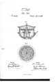
Figure2 isa horizontalsection, taken onlinez z onfig.1. I
My invention relates to that class of 'wheels in Figure 1 represents a .central vertical section of my which the water is supplied `under pressure throughclose'tubularconnections from a'qneducts, or similar 'g It consists First, in a combinatonwith the reaction or centri.
fugal `wheelof Barker or Whitlaw, Aof a series of stationaryaahu'tmentsfor the discharging water to impinge upon-, and thereby increase its reactive effectv when under pressure.
Secondly, in` such an arrangement of the "wheel within its housing as that the pressure applied fromv t below shall coiplnterbalance, or nearly so, the weight of the wheel, its shaft, and connections or gearing thereon.
if `"lhirdly, in the arrangement in relation toa pressure-wheel, of a regulating-valve or gate at the eduction-aperture, whereby all available pressure. is ob-l tained, and water cconomized. A
`Fourthlygn the arrangement of a hollow neck on the under side of the whcehfor forming connection t with't-he induction-pipe by-hydraulic packing, as hereinafter more particularly described.
`Referring to the drawingy A represents the reactionwheel, having two or more curvedwater-ways, a, which should be arranged todis charge an equal quantity. of water on opposite `sides, of the axis, to avoid lateral strain.
B is anannular rim, rmly'securedhi the housing 0 around the periphery of the wheel A, and'wh'ich is formed, at its'l `inner under side or edge, concave, in
which concave is arranged aseries of platesV lor divisions, c, which extend radially nearly in contact with the periphery ofthe wheel A, and downward about to the level of its under side. t -The housing G may be constructed in any convenient numberof parts," to facilitate the tting and intraduction ofthe working parts therein, and is provided with an induction-passage, D,in which is a cross-bar, d, with a step, to receivethe toerof the shaft b of the wheel A.
The upper end of this passage D is suitably fitted to form a water-packing around the neck fof the wheel, and to its lower end is attached the water-main `or supply-pipe.
.g is the egress-passage, which is tted with any suitable valve or gate, h, by which the consumption of water and consequent velocity and power otthe wheel may be regulated either by hand, or automatically, by a' governor. The housing G isalsc inclosed or covered in at top, and lnay be provided with astuio` ing-box around the shaft b, if desired.
The operation of' the wheel will then be as follows: The water being turned on at the induction-pas-` sage I), 'fillsthe wheel and the discharge-chamber be' ,y
neath it. The gate h is then to be withdrawn gradually until the required velocity ofthe wheel is attained, the water iiowing through the curved ways a, under pressure, discharges from the periphery ot' the wheel A against the abntments, which increase its reaction,
whilst the curvedportion of the rim between these abutments aids in the same bydefiecting. the waterfrom its direct course int-dthe discharge-chamber, and thence it escapes through the Vegress-opening g.
It will thus appear that, by the introduction et' the 'water under pressure to the under side of the wheel,
the weight ot" the latter is counterhalanced, and the friction of' 'its bearings is much reduced; also, that by the arrangement and combination of the abutlnents with'the wheel, the greatest amount of reaction is olle. tained and, by regulating the.A discharge-aperture insteadof the induction, thefull force of all .the water used is developed, less, only, that consumed in friction.
Having thus described inyinvention,`
,Whatl' claim as new, and desire to secure by Letters Patent, 'is- 1. 'The abutment-rim B, in. combination with theV reaction wheel A, all constructed and operating suhstantia'lly as shown Iand described.
2. The induction of the water on the under sident the wheel, in such manner that the weight of the lattially as shown and described.
` 3. The combination of the neck f, arranged on the under' 'side of the wheel, with the upward extension of the supply-pipe D, provided with hydraulic packing, substantially as described. I
WM. T. DUVALL.
f ter is sustained by the pressure of the water, substau. I
Witnesses:
SYDNEY E. SMITH, y W. MORRIS SMITH.
Publications (1)
| Publication Number | Publication Date |
|---|---|
| US103162A true US103162A (en) | 1870-05-17 |
Family
ID=2172649
Family Applications (1)
| Application Number | Title | Priority Date | Filing Date |
|---|---|---|---|
| US103162D Expired - Lifetime US103162A (en) | Improvement in water-wheel |
Country Status (1)
| Country | Link |
|---|---|
| US (1) | US103162A (en) |
Cited By (2)
| Publication number | Priority date | Publication date | Assignee | Title |
|---|---|---|---|---|
| US20110012370A1 (en) * | 2008-01-23 | 2011-01-20 | Cortes Julio | System for the transport of an ore pulp in a line system located along a gradient, and components of such a system |
| US20150233248A1 (en) * | 2012-08-08 | 2015-08-20 | C I Corporation Pty Ltd | Turbine assembly |
-
0
- US US103162D patent/US103162A/en not_active Expired - Lifetime
Cited By (4)
| Publication number | Priority date | Publication date | Assignee | Title |
|---|---|---|---|---|
| US20110012370A1 (en) * | 2008-01-23 | 2011-01-20 | Cortes Julio | System for the transport of an ore pulp in a line system located along a gradient, and components of such a system |
| US8461702B2 (en) * | 2008-01-23 | 2013-06-11 | Siemens Aktiengesellschaft | System for the transport of an ore pulp in a line system located along a gradient, and components of such a system |
| US20150233248A1 (en) * | 2012-08-08 | 2015-08-20 | C I Corporation Pty Ltd | Turbine assembly |
| US10544675B2 (en) * | 2012-08-08 | 2020-01-28 | C I Corporation Pty Ltd | Turbine assembly |
Similar Documents
| Publication | Publication Date | Title |
|---|---|---|
| US103162A (en) | Improvement in water-wheel | |
| US10026A (en) | Improvement in turbines | |
| US87625A (en) | Improvement in exterior casings for turbine water-wheels | |
| US396318A (en) | Haryey r | |
| US68039A (en) | District | |
| US483394A (en) | Wat er-motor | |
| US73215A (en) | Improvement in water-wheels | |
| US387791A (en) | Water-wheel | |
| US109891A (en) | Improvement in water-wheels | |
| USRE4539E (en) | Improvement in water-wheels | |
| US86238A (en) | Improvement in turbine water-wheels | |
| US111077A (en) | Improvement in water-wheels | |
| US104026A (en) | Improvement in water-wheels | |
| US67174A (en) | Robert dtjnbar | |
| US97591A (en) | Improvement in water-wheels | |
| US131161A (en) | Improvement in governors | |
| USRE3168E (en) | Improvement in water-wheels | |
| US56560A (en) | Improvement in water-wheels | |
| US101036A (en) | Improvement in water-wheels | |
| US110009A (en) | Improvement in water-wheels | |
| US48737A (en) | Improvement in water-wheels | |
| US600737A (en) | Charles t | |
| US118778A (en) | Improvement in water-wheel cases | |
| US390847A (en) | Water-wheel | |
| US281459A (en) | Tbeeitoey |