US10312451B2 - Compound for organic electroluminescent device - Google Patents
Compound for organic electroluminescent device Download PDFInfo
- Publication number
- US10312451B2 US10312451B2 US14/949,830 US201514949830A US10312451B2 US 10312451 B2 US10312451 B2 US 10312451B2 US 201514949830 A US201514949830 A US 201514949830A US 10312451 B2 US10312451 B2 US 10312451B2
- Authority
- US
- United States
- Prior art keywords
- substituted
- group
- unsubstituted
- carbon atoms
- compound
- Prior art date
- Legal status (The legal status is an assumption and is not a legal conclusion. Google has not performed a legal analysis and makes no representation as to the accuracy of the status listed.)
- Expired - Fee Related, expires
Links
- 0 *.C*[Ar]C.C1=CC2=C3C=CC=CC3=C3/C=C\C=C/C3=C2C=C1.[1*]C.[2*]C([3*])(C)CCC Chemical compound *.C*[Ar]C.C1=CC2=C3C=CC=CC3=C3/C=C\C=C/C3=C2C=C1.[1*]C.[2*]C([3*])(C)CCC 0.000 description 6
- FUJBXRKJMGUQFP-UHFFFAOYSA-N CC(C)(C)C1=CC=C(C(C)(C)C)C=C1.CC(C)(C)C1=CC=C(C2=CC(C(C)(C)C)=CC=C2)C=C1.CC(C)(C)C1=CC=C(C2=CC=C(C(C)(C)C)C=C2)C=C1.CC(C)(C)C1=CC=CC(C(C)(C)C)=C1.CC(C)(C)C1=CC=CC(C2=C(C(C)(C)C)C=CC=C2)=C1.CC(C)(C)C1=CC=CC(C2=CC=CC(C(C)(C)C)=C2)=C1.CC(C)(C)C1=CC=CC=C1C(C)(C)C.CC1=CC(C(C)(C)C)=CC(C(C)(C)C)=C1 Chemical compound CC(C)(C)C1=CC=C(C(C)(C)C)C=C1.CC(C)(C)C1=CC=C(C2=CC(C(C)(C)C)=CC=C2)C=C1.CC(C)(C)C1=CC=C(C2=CC=C(C(C)(C)C)C=C2)C=C1.CC(C)(C)C1=CC=CC(C(C)(C)C)=C1.CC(C)(C)C1=CC=CC(C2=C(C(C)(C)C)C=CC=C2)=C1.CC(C)(C)C1=CC=CC(C2=CC=CC(C(C)(C)C)=C2)=C1.CC(C)(C)C1=CC=CC=C1C(C)(C)C.CC1=CC(C(C)(C)C)=CC(C(C)(C)C)=C1 FUJBXRKJMGUQFP-UHFFFAOYSA-N 0.000 description 4
- CPTQXGOAJQFTHA-UHFFFAOYSA-N CC(C)(C)C1=C2C=CC=CC2=C(C(C)(C)C)C2=C1C=CC=C2.CC(C)(C)C1=CC2=C(C=C1)C1=C(C=C2)C=C(C(C)(C)C)C=C1.CC(C)(C)C1=CC2=C3C=CC=CC3=C(C(C)(C)C)C=C2C2=C1C=CC=C2.CC(C)(C)C1=CC=C(C(C)(C)C)C2=C1C=CC=C2.CC(C)(C)C1=CC=C(C(C)(C)C)C=C1.CC(C)(C)C1=CC=C2/C=C\C3=C(C(C)(C)C)C=CC4=C3C2=C1C=C4.CC(C)(C)C1=CC=C2C=C(C(C)(C)C)C=CC2=C1.CC(C)(C)C1=CC=C2C=C3C=C(C(C)(C)C)C=CC3=CC2=C1.CC(C)(C)C1=CC=CC(C(C)(C)C)=C1.CC(C)(C)C1=CC=CC2=C1C=CC1=C2C=CC=C1C(C)(C)C.CC(C)(C)C1=CC=CC2=C1C=CC=C2C(C)(C)C.CC(C)(C)C1=CC=CC=C1C(C)(C)C Chemical compound CC(C)(C)C1=C2C=CC=CC2=C(C(C)(C)C)C2=C1C=CC=C2.CC(C)(C)C1=CC2=C(C=C1)C1=C(C=C2)C=C(C(C)(C)C)C=C1.CC(C)(C)C1=CC2=C3C=CC=CC3=C(C(C)(C)C)C=C2C2=C1C=CC=C2.CC(C)(C)C1=CC=C(C(C)(C)C)C2=C1C=CC=C2.CC(C)(C)C1=CC=C(C(C)(C)C)C=C1.CC(C)(C)C1=CC=C2/C=C\C3=C(C(C)(C)C)C=CC4=C3C2=C1C=C4.CC(C)(C)C1=CC=C2C=C(C(C)(C)C)C=CC2=C1.CC(C)(C)C1=CC=C2C=C3C=C(C(C)(C)C)C=CC3=CC2=C1.CC(C)(C)C1=CC=CC(C(C)(C)C)=C1.CC(C)(C)C1=CC=CC2=C1C=CC1=C2C=CC=C1C(C)(C)C.CC(C)(C)C1=CC=CC2=C1C=CC=C2C(C)(C)C.CC(C)(C)C1=CC=CC=C1C(C)(C)C CPTQXGOAJQFTHA-UHFFFAOYSA-N 0.000 description 3
- MXYOJUGTHHRTHI-UHFFFAOYSA-N CC(C)(C)C1=C2C=CC=CC2=CC2=C1C=CC=C2.CC(C)(C)C1=CC2=C(C=C1)C1=C(C=CC=C1)C=C2.CC(C)(C)C1=CC2=C(C=CC3=C2C=CC=C3)C2=C1C=CC=C2.CC(C)(C)C1=CC2=C(C=CC=C2)C=C1.CC(C)(C)C1=CC=C(C2=C3C=CC=CC3=CC=C2)C=C1.CC(C)(C)C1=CC=C(C2=CC3=C(C=CC=C3)C=C2)C=C1.CC(C)(C)C1=CC=C2/C=C\C3=CC=CC4=C3C2=C1C=C4.CC(C)(C)C1=CC=C2C=C3C=CC=CC3=CC2=C1.CC(C)(C)C1=CC=CC(C2=CC=C3C=CC=CC3=C2)=C1.CC(C)(C)C1=CC=CC(C2=CC=CC3=C2C=CC=C3)=C1.CC(C)(C)C1=CC=CC2=C1C=CC=C2.CC(C)(C)C1=CC=CC2=C3C=CC=CC3=CC=C12.CC(C)(C)C1=CC=CC=C1 Chemical compound CC(C)(C)C1=C2C=CC=CC2=CC2=C1C=CC=C2.CC(C)(C)C1=CC2=C(C=C1)C1=C(C=CC=C1)C=C2.CC(C)(C)C1=CC2=C(C=CC3=C2C=CC=C3)C2=C1C=CC=C2.CC(C)(C)C1=CC2=C(C=CC=C2)C=C1.CC(C)(C)C1=CC=C(C2=C3C=CC=CC3=CC=C2)C=C1.CC(C)(C)C1=CC=C(C2=CC3=C(C=CC=C3)C=C2)C=C1.CC(C)(C)C1=CC=C2/C=C\C3=CC=CC4=C3C2=C1C=C4.CC(C)(C)C1=CC=C2C=C3C=CC=CC3=CC2=C1.CC(C)(C)C1=CC=CC(C2=CC=C3C=CC=CC3=C2)=C1.CC(C)(C)C1=CC=CC(C2=CC=CC3=C2C=CC=C3)=C1.CC(C)(C)C1=CC=CC2=C1C=CC=C2.CC(C)(C)C1=CC=CC2=C3C=CC=CC3=CC=C12.CC(C)(C)C1=CC=CC=C1 MXYOJUGTHHRTHI-UHFFFAOYSA-N 0.000 description 3
- MLWDCTVDXNRROA-UHFFFAOYSA-N BrC1=C2C=CC=CC2=C(C2=CC=C(C3=CC=CC4=C3C=CC=C4)CC2)C2=C1C=CC=C2.OB(O)C1=C2C=CC=CC2=C(C2=CC=C(C3=CC=CC4=C3C=CC=C4)CC2)C2=C1C=CC=C2 Chemical compound BrC1=C2C=CC=CC2=C(C2=CC=C(C3=CC=CC4=C3C=CC=C4)CC2)C2=C1C=CC=C2.OB(O)C1=C2C=CC=CC2=C(C2=CC=C(C3=CC=CC4=C3C=CC=C4)CC2)C2=C1C=CC=C2 MLWDCTVDXNRROA-UHFFFAOYSA-N 0.000 description 1
- BKLAKACTRKXZIC-UHFFFAOYSA-N BrC1=CC=C(Br)C=C1.BrC1=CC=C(C2=CC=C3/C=C\C4=C(C5=CC=CC6=C5C=CC=C6)C=CC5=CC=C2C3=C54)C=C1.CC1(C)OB(C2=CC=C3/C=C\C4=C(C5=CC=CC6=C5C=CC=C6)C=CC5=CC=C2C3=C54)OC1(C)C Chemical compound BrC1=CC=C(Br)C=C1.BrC1=CC=C(C2=CC=C3/C=C\C4=C(C5=CC=CC6=C5C=CC=C6)C=CC5=CC=C2C3=C54)C=C1.CC1(C)OB(C2=CC=C3/C=C\C4=C(C5=CC=CC6=C5C=CC=C6)C=CC5=CC=C2C3=C54)OC1(C)C BKLAKACTRKXZIC-UHFFFAOYSA-N 0.000 description 1
- HMWUOUXTUYETIK-UHFFFAOYSA-N BrC1=CC=C(Br)C=C1.BrC1=CC=C(C2=CC=C3/C=C\C4=C(C5=CC=CC=C5)C=CC5=CC=C2C3=C54)C=C1.CC1(C)OB(C2=CC=C3/C=C\C4=C(C5=CC=CC=C5)C=CC5=CC=C2C3=C54)OC1(C)C Chemical compound BrC1=CC=C(Br)C=C1.BrC1=CC=C(C2=CC=C3/C=C\C4=C(C5=CC=CC=C5)C=CC5=CC=C2C3=C54)C=C1.CC1(C)OB(C2=CC=C3/C=C\C4=C(C5=CC=CC=C5)C=CC5=CC=C2C3=C54)OC1(C)C HMWUOUXTUYETIK-UHFFFAOYSA-N 0.000 description 1
- FHLWQIBBPCGKRV-UHFFFAOYSA-N BrC1=CC=C(C2=CC=C3/C=C\C4=C(C5=CC=CC6=C5C=CC=C6)C=CC5=CC=C2C3=C54)C=C1.CC1(C)OB(B2OC(C)(C)C(C)(C)O2)OC1(C)C.CC1(C)OB(C2=CC=C(C3=CC=C4/C=C\C5=C(C6=CC=CC7=C6C=CC=C7)C=CC6=CC=C3C4=C65)C=C2)OC1(C)C Chemical compound BrC1=CC=C(C2=CC=C3/C=C\C4=C(C5=CC=CC6=C5C=CC=C6)C=CC5=CC=C2C3=C54)C=C1.CC1(C)OB(B2OC(C)(C)C(C)(C)O2)OC1(C)C.CC1(C)OB(C2=CC=C(C3=CC=C4/C=C\C5=C(C6=CC=CC7=C6C=CC=C7)C=CC6=CC=C3C4=C65)C=C2)OC1(C)C FHLWQIBBPCGKRV-UHFFFAOYSA-N 0.000 description 1
- RQRCPMHXNPTCSS-UHFFFAOYSA-N BrC1=CC=C(C2=CC=C3/C=C\C4=C(C5=CC=CC=C5)C=CC5=CC=C2C3=C54)C=C1.CC1(C)OB(B2OC(C)(C)C(C)(C)O2)OC1(C)C.CC1(C)OB(C2=CC=C(C3=CC=C4/C=C\C5=C(C6=CC=CC=C6)C=CC6=CC=C3C4=C65)C=C2)OC1(C)C Chemical compound BrC1=CC=C(C2=CC=C3/C=C\C4=C(C5=CC=CC=C5)C=CC5=CC=C2C3=C54)C=C1.CC1(C)OB(B2OC(C)(C)C(C)(C)O2)OC1(C)C.CC1(C)OB(C2=CC=C(C3=CC=C4/C=C\C5=C(C6=CC=CC=C6)C=CC6=CC=C3C4=C65)C=C2)OC1(C)C RQRCPMHXNPTCSS-UHFFFAOYSA-N 0.000 description 1
- PJVKGCLKGCURAE-UHFFFAOYSA-N BrC1=CC=C2/C=C\C3=C(C4=CC=CC5=C4C=CC=C5)C=CC4=CC=C1C2=C43.CC1(C)OB(B2OC(C)(C)C(C)(C)O2)OC1(C)C.CC1(C)OB(C2=CC=C3/C=C\C4=C(C5=CC=CC6=C5C=CC=C6)C=CC5=CC=C2C3=C54)OC1(C)C Chemical compound BrC1=CC=C2/C=C\C3=C(C4=CC=CC5=C4C=CC=C5)C=CC4=CC=C1C2=C43.CC1(C)OB(B2OC(C)(C)C(C)(C)O2)OC1(C)C.CC1(C)OB(C2=CC=C3/C=C\C4=C(C5=CC=CC6=C5C=CC=C6)C=CC5=CC=C2C3=C54)OC1(C)C PJVKGCLKGCURAE-UHFFFAOYSA-N 0.000 description 1
- WCVHYKWRAUDUSW-UHFFFAOYSA-N BrC1=CC=C2/C=C\C3=C(C4=CC=CC=C4)C=CC4=CC=C1C2=C43.CC1(C)OB(B2OC(C)(C)C(C)(C)O2)OC1(C)C.CC1(C)OB(C2=CC=C3/C=C\C4=C(C5=CC=CC=C5)C=CC5=CC=C2C3=C54)OC1(C)C Chemical compound BrC1=CC=C2/C=C\C3=C(C4=CC=CC=C4)C=CC4=CC=C1C2=C43.CC1(C)OB(B2OC(C)(C)C(C)(C)O2)OC1(C)C.CC1(C)OB(C2=CC=C3/C=C\C4=C(C5=CC=CC=C5)C=CC5=CC=C2C3=C54)OC1(C)C WCVHYKWRAUDUSW-UHFFFAOYSA-N 0.000 description 1
- GQIVLDOKVLOHSH-UHFFFAOYSA-N C.CC(C)(C)C1=C2C=CC=CC2=C(C(C)(C)C)C2=C1C=CC=C2.CC(C)(C)C1=CC2=C(C=C1)C1=C(C=C2)C=C(C(C)(C)C)C=C1.CC(C)(C)C1=CC=C(C(C)(C)C)C2=C1C=CC=C2.CC(C)(C)C1=CC=C(C(C)(C)C)C=C1.CC(C)(C)C1=CC=C2C=C(C(C)(C)C)C=CC2=C1.CC(C)(C)C1=CC=C2C=C3C=C(C(C)(C)C)C=CC3=CC2=C1.CC(C)(C)C1=CC=CC(C(C)(C)C)=C1.CC(C)(C)C1=CC=CC2=C1C=CC1=C2C=CC=C1C(C)(C)C.CC(C)(C)C1=CC=CC2=C1C=CC=C2C(C)(C)C.CC(C)(C)C1=CC=CC=C1C(C)(C)C Chemical compound C.CC(C)(C)C1=C2C=CC=CC2=C(C(C)(C)C)C2=C1C=CC=C2.CC(C)(C)C1=CC2=C(C=C1)C1=C(C=C2)C=C(C(C)(C)C)C=C1.CC(C)(C)C1=CC=C(C(C)(C)C)C2=C1C=CC=C2.CC(C)(C)C1=CC=C(C(C)(C)C)C=C1.CC(C)(C)C1=CC=C2C=C(C(C)(C)C)C=CC2=C1.CC(C)(C)C1=CC=C2C=C3C=C(C(C)(C)C)C=CC3=CC2=C1.CC(C)(C)C1=CC=CC(C(C)(C)C)=C1.CC(C)(C)C1=CC=CC2=C1C=CC1=C2C=CC=C1C(C)(C)C.CC(C)(C)C1=CC=CC2=C1C=CC=C2C(C)(C)C.CC(C)(C)C1=CC=CC=C1C(C)(C)C GQIVLDOKVLOHSH-UHFFFAOYSA-N 0.000 description 1
- TXXINFRUXZFIJX-UHFFFAOYSA-N C1=CC=C(C2=CC(C3=CC4=C(C=CC=C4)C=C3)=NC3=C4/N=C(C5=CC=C6C=CC=CC6=C5)\C=C(\C5=CC=CC=C5)C4=CC=C23)C=C1.C1=CC=C2C(=C1)[Ir]N1=CC=CC=C21.CC1(C)C2=C(C=C(C3=NC(C4=CC(C5=CC=CC=C5)=CC(C5=CC=CC=C5)=C4)=NC(C4=CC(C5=CC=CC=C5)=CC(C5=CC=CC=C5)=C4)=N3)C=C2)C2=C/C3=C(\C=C/21)C1=C(C=CC=C1)C1=C3C=CC=C1.CC1(C)C2=CC3=C(C=C2C2=C1C=CC(C1=C4SC5=C(C=CC=C5)C4=CC=C1)=C2)C1=C(C=CC=C1)C1=C3C=CC=C1.CC1(C)C2=CC3=C4C=CC(C5=C6C=CC=CC6=C(C6=CC=C7C=CC=CC7=C6)C6=C5C=CC=C6)=CC4=C4C=CC=CC4=C3C=C2C2=C1C=CC=C2.CC1(C)C2=CC3=C4C=CC(C5=CC=C(C6=C7C=CC=CC7=C(C7=CC=C8C=CC=CC8=C7)C7=C6C=CC=C7)C=C5)=CC4=C4C=CC=CC4=C3C=C2C2=C1C=CC=C2.CC1(C)C2=CC3=C4C=CC(C5=CC=CC(C6=CC(C7=CC=CC(C8=CC=CC=C8)=C7)=CC=C6)=C5)=CC4=C4C=CC=CC4=C3C=C2C2=C1C=CC=C2 Chemical compound C1=CC=C(C2=CC(C3=CC4=C(C=CC=C4)C=C3)=NC3=C4/N=C(C5=CC=C6C=CC=CC6=C5)\C=C(\C5=CC=CC=C5)C4=CC=C23)C=C1.C1=CC=C2C(=C1)[Ir]N1=CC=CC=C21.CC1(C)C2=C(C=C(C3=NC(C4=CC(C5=CC=CC=C5)=CC(C5=CC=CC=C5)=C4)=NC(C4=CC(C5=CC=CC=C5)=CC(C5=CC=CC=C5)=C4)=N3)C=C2)C2=C/C3=C(\C=C/21)C1=C(C=CC=C1)C1=C3C=CC=C1.CC1(C)C2=CC3=C(C=C2C2=C1C=CC(C1=C4SC5=C(C=CC=C5)C4=CC=C1)=C2)C1=C(C=CC=C1)C1=C3C=CC=C1.CC1(C)C2=CC3=C4C=CC(C5=C6C=CC=CC6=C(C6=CC=C7C=CC=CC7=C6)C6=C5C=CC=C6)=CC4=C4C=CC=CC4=C3C=C2C2=C1C=CC=C2.CC1(C)C2=CC3=C4C=CC(C5=CC=C(C6=C7C=CC=CC7=C(C7=CC=C8C=CC=CC8=C7)C7=C6C=CC=C7)C=C5)=CC4=C4C=CC=CC4=C3C=C2C2=C1C=CC=C2.CC1(C)C2=CC3=C4C=CC(C5=CC=CC(C6=CC(C7=CC=CC(C8=CC=CC=C8)=C7)=CC=C6)=C5)=CC4=C4C=CC=CC4=C3C=C2C2=C1C=CC=C2 TXXINFRUXZFIJX-UHFFFAOYSA-N 0.000 description 1
- WRRAXQNNROGTTK-UHFFFAOYSA-N CC(C)(C)/C1=C/C=C2/C=C\C3=CC=CC4=C3C2=C1C=C4.CC(C)(C)C1=CC2=C(C=CC3=C2C=CC=C3)C2=C1C=CC=C2 Chemical compound CC(C)(C)/C1=C/C=C2/C=C\C3=CC=CC4=C3C2=C1C=C4.CC(C)(C)C1=CC2=C(C=CC3=C2C=CC=C3)C2=C1C=CC=C2 WRRAXQNNROGTTK-UHFFFAOYSA-N 0.000 description 1
- DMKPTIARFPLVMG-UHFFFAOYSA-N CC(C)(C)C1=C2/C=C\C3=C\C=C(\C(C)(C)C)C4=C3C2=C(C=C4)C=C1.CC(C)(C)C1=CC2=C(C=C(C(C)(C)C)C3=C2C=CC=C3)C2=C1C=CC=C2 Chemical compound CC(C)(C)C1=C2/C=C\C3=C\C=C(\C(C)(C)C)C4=C3C2=C(C=C4)C=C1.CC(C)(C)C1=CC2=C(C=C(C(C)(C)C)C3=C2C=CC=C3)C2=C1C=CC=C2 DMKPTIARFPLVMG-UHFFFAOYSA-N 0.000 description 1
- OGGUKDJOCPSZCG-UHFFFAOYSA-N CC(C)(C)C1=C2C=CC=CC2=CC2=C1C=CC=C2.CC(C)(C)C1=CC2=C(C=C1)C1=C(C=CC=C1)C=C2.CC(C)(C)C1=CC2=C(C=CC=C2)C=C1.CC(C)(C)C1=CC=C(C2=C3C=CC=CC3=CC=C2)C=C1.CC(C)(C)C1=CC=C(C2=CC3=C(C=CC=C3)C=C2)C=C1.CC(C)(C)C1=CC=C2C=C3C=CC=CC3=CC2=C1.CC(C)(C)C1=CC=CC(C2=CC=C3C=CC=CC3=C2)=C1.CC(C)(C)C1=CC=CC(C2=CC=CC3=C2C=CC=C3)=C1.CC(C)(C)C1=CC=CC2=C1C=CC=C2.CC(C)(C)C1=CC=CC2=C3C=CC=CC3=CC=C12.CC(C)(C)C1=CC=CC=C1 Chemical compound CC(C)(C)C1=C2C=CC=CC2=CC2=C1C=CC=C2.CC(C)(C)C1=CC2=C(C=C1)C1=C(C=CC=C1)C=C2.CC(C)(C)C1=CC2=C(C=CC=C2)C=C1.CC(C)(C)C1=CC=C(C2=C3C=CC=CC3=CC=C2)C=C1.CC(C)(C)C1=CC=C(C2=CC3=C(C=CC=C3)C=C2)C=C1.CC(C)(C)C1=CC=C2C=C3C=CC=CC3=CC2=C1.CC(C)(C)C1=CC=CC(C2=CC=C3C=CC=CC3=C2)=C1.CC(C)(C)C1=CC=CC(C2=CC=CC3=C2C=CC=C3)=C1.CC(C)(C)C1=CC=CC2=C1C=CC=C2.CC(C)(C)C1=CC=CC2=C3C=CC=CC3=CC=C12.CC(C)(C)C1=CC=CC=C1 OGGUKDJOCPSZCG-UHFFFAOYSA-N 0.000 description 1
- UEAYUEQFYJAXKW-UHFFFAOYSA-N CC1(C)C2=C(C3=C(C=CC=C3)C3=C2C=CC=C3)C2=C/C3=C4C=CC=CC4=C4C=C(C5=CC=C(C6=CC=C(C7=CC8=C(C=CC9=C8C=CC=C9)C8=C7C=CC=C8)C=C6)C=C5)C=CC4=C3/C=C\21.CC1(C)C2=C(C=C3C(=C2)C2=C(C=CC=C2)C2=C3C=CC=C2)C2=C/C3=C4C=CC=CC4=C4C=C(C5=CC=C(C6=C7C=CC=CC7=C(C7=CC=C(C8=CC=CC9=C8C=CC=C9)C=C7)C7=C6C=CC=C7)C=C5)C=CC4=C3/C=C\21.CC1(C)C2=C(C=CC=C2)C2=C/C3=C4C=CC=CC4=C4C=C(C5=CC=C(C6=C7C=CC=CC7=C7C=C(C8=CC=CC=C8)C8=C(C=CC=C8)C7=C6)C=C5)C=CC4=C3/C=C\21.CC1(C)C2=C(C=CC=C2)C2=C/C3=C4C=CC=CC4=C4C=C(C5=CC=C(C6=CC=C7/C=C\C8=C9C(=CC=C8C8=C%10C=CC=CC%10=CC=C8)C=CC6=C79)C=C5)C=CC4=C3/C=C\21 Chemical compound CC1(C)C2=C(C3=C(C=CC=C3)C3=C2C=CC=C3)C2=C/C3=C4C=CC=CC4=C4C=C(C5=CC=C(C6=CC=C(C7=CC8=C(C=CC9=C8C=CC=C9)C8=C7C=CC=C8)C=C6)C=C5)C=CC4=C3/C=C\21.CC1(C)C2=C(C=C3C(=C2)C2=C(C=CC=C2)C2=C3C=CC=C2)C2=C/C3=C4C=CC=CC4=C4C=C(C5=CC=C(C6=C7C=CC=CC7=C(C7=CC=C(C8=CC=CC9=C8C=CC=C9)C=C7)C7=C6C=CC=C7)C=C5)C=CC4=C3/C=C\21.CC1(C)C2=C(C=CC=C2)C2=C/C3=C4C=CC=CC4=C4C=C(C5=CC=C(C6=C7C=CC=CC7=C7C=C(C8=CC=CC=C8)C8=C(C=CC=C8)C7=C6)C=C5)C=CC4=C3/C=C\21.CC1(C)C2=C(C=CC=C2)C2=C/C3=C4C=CC=CC4=C4C=C(C5=CC=C(C6=CC=C7/C=C\C8=C9C(=CC=C8C8=C%10C=CC=CC%10=CC=C8)C=CC6=C79)C=C5)C=CC4=C3/C=C\21 UEAYUEQFYJAXKW-UHFFFAOYSA-N 0.000 description 1
- LMMFGSYFJJXUGL-UHFFFAOYSA-N CC1(C)C2=C(C3=C(C=CC=C3)C3=C2C=CC=C3)C2=C/C3=C4C=CC=CC4=C4C=C(C5=CC=C(C6=CC=C(C7=CC8=C(C=CC9=C8C=CC=C9)C8=C7C=CC=C8)C=C6)C=C5)C=CC4=C3/C=C\21.CC1(C)C2=C(C=CC=C2)C2=C/C3=C4C=CC=CC4=C4C=C(C5=CC=C(C6=C7C=CC=CC7=C7C=C(C8=CC=CC=C8)C8=C(C=CC=C8)C7=C6)C=C5)C=CC4=C3/C=C\21.CC1(C)C2=C(C=CC=C2)C2=C/C3=C4C=CC=CC4=C4C=C(C5=CC=C(C6=CC=C(C7=CC8=C(C=CC9=C8C=CC=C9)C8=C7C=CC=C8)C=C6)C=C5)C=CC4=C3/C=C\21.CC1(C)C2=C(C=CC=C2)C2=C/C3=C4C=CC=CC4=C4C=C(C5=CC=C(C6=CC=C(C7=CC=CC8=C7C=CC7=CC=CC=C78)C=C6)C=C5)C=CC4=C3/C=C\21.CC1(C)C2=C(C=CC=C2)C2=C/C3=C4C=CC=CC4=C4C=C(C5=CC=C(C6=CC=C7/C=C\C8=C9C(=CC=C8C8=CC=CC=C8)C=CC6=C79)C=C5)C=CC4=C3/C=C\21 Chemical compound CC1(C)C2=C(C3=C(C=CC=C3)C3=C2C=CC=C3)C2=C/C3=C4C=CC=CC4=C4C=C(C5=CC=C(C6=CC=C(C7=CC8=C(C=CC9=C8C=CC=C9)C8=C7C=CC=C8)C=C6)C=C5)C=CC4=C3/C=C\21.CC1(C)C2=C(C=CC=C2)C2=C/C3=C4C=CC=CC4=C4C=C(C5=CC=C(C6=C7C=CC=CC7=C7C=C(C8=CC=CC=C8)C8=C(C=CC=C8)C7=C6)C=C5)C=CC4=C3/C=C\21.CC1(C)C2=C(C=CC=C2)C2=C/C3=C4C=CC=CC4=C4C=C(C5=CC=C(C6=CC=C(C7=CC8=C(C=CC9=C8C=CC=C9)C8=C7C=CC=C8)C=C6)C=C5)C=CC4=C3/C=C\21.CC1(C)C2=C(C=CC=C2)C2=C/C3=C4C=CC=CC4=C4C=C(C5=CC=C(C6=CC=C(C7=CC=CC8=C7C=CC7=CC=CC=C78)C=C6)C=C5)C=CC4=C3/C=C\21.CC1(C)C2=C(C=CC=C2)C2=C/C3=C4C=CC=CC4=C4C=C(C5=CC=C(C6=CC=C7/C=C\C8=C9C(=CC=C8C8=CC=CC=C8)C=CC6=C79)C=C5)C=CC4=C3/C=C\21 LMMFGSYFJJXUGL-UHFFFAOYSA-N 0.000 description 1
- WOKJLMIGPDCKGT-UHFFFAOYSA-N CC1(C)C2=C(C3=C(C=CC=C3)C=C2)C2=C/C3=C4C=CC=CC4=C4C=C(C5=CC=C(C6=C7C=CC=CC7=C(C7=CC=C(C8=CC=C9C=CC=CC9=C8)C=C7)C7=C6C=CC=C7)C=C5)C=CC4=C3/C=C\21.CC1(C)C2=C(C3=C(C=CC=C3)C=C2)C2=C/C3=C4C=CC=CC4=C4C=C(C5=CC=C(C6=C7C=CC=CC7=C(C7=CC=CC(C8=C9C=CC=CC9=CC=C8)=C7)C7=C6C=CC=C7)C=C5)C=CC4=C3/C=C\21.CC1(C)C2=C(C3=C(C=CC=C3)C=C2)C2=C/C3=C4C=CC=CC4=C4C=C(C5=CC=C(C6=C7C=CC=CC7=C(C7=CC=CC(C8=CC9=C(C=CC=C9)C=C8)=C7)C7=C6C=CC=C7)C=C5)C=CC4=C3/C=C\21.CC1(C)C2=C(C3=C(C=CC=C3)C=C2)C2=C/C3=C4C=CC=CC4=C4C=C(C5=CC=C(C6=CC=C7/C=C\C8=C9C(=CC=C8)C=CC6=C79)C=C5)C=CC4=C3/C=C\21.CC1(C)C2=C(C=CC=C2)C2=C/C3=C4C=CC=CC4=C4C=C(C5=CC=C(C6=CC=C(C7=CC=C8/C=C\C9=C%10C(=CC=C9)C=CC7=C8%10)C=C6)C=C5)C=CC4=C3/C=C\21.CC1(C)C2=C(C=CC=C2)C2=C/C3=C4C=CC=CC4=C4C=C(C5=CC=C(C6=CC=CC(C7=CC=C8/C=C\C9=C%10C(=CC=C9)C=CC7=C8%10)=C6)C=C5)C=CC4=C3/C=C\21 Chemical compound CC1(C)C2=C(C3=C(C=CC=C3)C=C2)C2=C/C3=C4C=CC=CC4=C4C=C(C5=CC=C(C6=C7C=CC=CC7=C(C7=CC=C(C8=CC=C9C=CC=CC9=C8)C=C7)C7=C6C=CC=C7)C=C5)C=CC4=C3/C=C\21.CC1(C)C2=C(C3=C(C=CC=C3)C=C2)C2=C/C3=C4C=CC=CC4=C4C=C(C5=CC=C(C6=C7C=CC=CC7=C(C7=CC=CC(C8=C9C=CC=CC9=CC=C8)=C7)C7=C6C=CC=C7)C=C5)C=CC4=C3/C=C\21.CC1(C)C2=C(C3=C(C=CC=C3)C=C2)C2=C/C3=C4C=CC=CC4=C4C=C(C5=CC=C(C6=C7C=CC=CC7=C(C7=CC=CC(C8=CC9=C(C=CC=C9)C=C8)=C7)C7=C6C=CC=C7)C=C5)C=CC4=C3/C=C\21.CC1(C)C2=C(C3=C(C=CC=C3)C=C2)C2=C/C3=C4C=CC=CC4=C4C=C(C5=CC=C(C6=CC=C7/C=C\C8=C9C(=CC=C8)C=CC6=C79)C=C5)C=CC4=C3/C=C\21.CC1(C)C2=C(C=CC=C2)C2=C/C3=C4C=CC=CC4=C4C=C(C5=CC=C(C6=CC=C(C7=CC=C8/C=C\C9=C%10C(=CC=C9)C=CC7=C8%10)C=C6)C=C5)C=CC4=C3/C=C\21.CC1(C)C2=C(C=CC=C2)C2=C/C3=C4C=CC=CC4=C4C=C(C5=CC=C(C6=CC=CC(C7=CC=C8/C=C\C9=C%10C(=CC=C9)C=CC7=C8%10)=C6)C=C5)C=CC4=C3/C=C\21 WOKJLMIGPDCKGT-UHFFFAOYSA-N 0.000 description 1
- OZWWFDOWBWISCR-UHFFFAOYSA-N CC1(C)C2=C(C3=C(C=CC=C3)C=C2)C2=C/C3=C4C=CC=CC4=C4C=C(C5=CC=C(C6=C7C=CC=CC7=C(C7=CC=C(C8=CC=C9C=CC=CC9=C8)C=C7)C7=C6C=CC=C7)C=C5)C=CC4=C3/C=C\21.CC1(C)C2=C(C3=C(C=CC=C3)C=C2)C2=C/C3=C4C=CC=CC4=C4C=C(C5=CC=C(C6=C7C=CC=CC7=C(C7=CC=CC(C8=C9C=CC=CC9=CC=C8)=C7)C7=C6C=CC=C7)C=C5)C=CC4=C3/C=C\21.CC1(C)C2=C(C3=C(C=CC=C3)C=C2)C2=C/C3=C4C=CC=CC4=C4C=C(C5=CC=C(C6=C7C=CC=CC7=C(C7=CC=CC(C8=CC9=C(C=CC=C9)C=C8)=C7)C7=C6C=CC=C7)C=C5)C=CC4=C3/C=C\21.CC1(C)C2=C(C=CC=C2)C2=C/C3=C4C=CC=CC4=C4C=C(C5=CC=C(C6=CC=C(C7=CC=C8/C=C\C9=C%10C(=CC=C9)C=CC7=C8%10)C=C6)C=C5)C=CC4=C3/C=C\21 Chemical compound CC1(C)C2=C(C3=C(C=CC=C3)C=C2)C2=C/C3=C4C=CC=CC4=C4C=C(C5=CC=C(C6=C7C=CC=CC7=C(C7=CC=C(C8=CC=C9C=CC=CC9=C8)C=C7)C7=C6C=CC=C7)C=C5)C=CC4=C3/C=C\21.CC1(C)C2=C(C3=C(C=CC=C3)C=C2)C2=C/C3=C4C=CC=CC4=C4C=C(C5=CC=C(C6=C7C=CC=CC7=C(C7=CC=CC(C8=C9C=CC=CC9=CC=C8)=C7)C7=C6C=CC=C7)C=C5)C=CC4=C3/C=C\21.CC1(C)C2=C(C3=C(C=CC=C3)C=C2)C2=C/C3=C4C=CC=CC4=C4C=C(C5=CC=C(C6=C7C=CC=CC7=C(C7=CC=CC(C8=CC9=C(C=CC=C9)C=C8)=C7)C7=C6C=CC=C7)C=C5)C=CC4=C3/C=C\21.CC1(C)C2=C(C=CC=C2)C2=C/C3=C4C=CC=CC4=C4C=C(C5=CC=C(C6=CC=C(C7=CC=C8/C=C\C9=C%10C(=CC=C9)C=CC7=C8%10)C=C6)C=C5)C=CC4=C3/C=C\21 OZWWFDOWBWISCR-UHFFFAOYSA-N 0.000 description 1
- LWQUCZXJFFMGRQ-UHFFFAOYSA-N CC1(C)C2=C(C3=C(C=CC=C3)C=C2)C2=C/C3=C4C=CC=CC4=C4C=C(C5=CC=C(C6=C7C=CC=CC7=C(C7=CC=C(C8=CC=CC9=C8C=CC=C9)C=C7)C7=C6C=CC=C7)C=C5)C=CC4=C3/C=C\21.CC1(C)C2=C(C=CC=C2)C2=C/C3=C4C=CC=CC4=C4C=C(C5=C6C=CC=CC6=C(C6=CC=C(C7=CC=CC8=C7C=CC=C8)C=C6)C6=C5C=CC=C6)C=CC4=C3/C=C\21.CC1(C)C2=C(C=CC=C2)C2=C/C3=C4C=CC=CC4=C4C=C(C5=CC=C(C6=C7C=CC=CC7=C(C7=CC=C(C8=CC=C9C=CC=CC9=C8)C=C7)C7=C6C=CC=C7)C=C5)C=CC4=C3/C=C\21.CC1(C)C2=C(C=CC=C2)C2=C/C3=C4C=CC=CC4=C4C=C(C5=CC=C(C6=C7C=CC=CC7=C(C7=CC=C(C8=CC=CC9=C8C=CC=C9)C=C7)C7=C6C=CC=C7)C=C5)C=CC4=C3/C=C\21.CC1(C)C2=C(C=CC=C2)C2=C/C3=C4C=CC=CC4=C4C=C(C5=CC=C(C6=C7C=CC=CC7=C(C7=CC=CC(C8=C9C=CC=CC9=CC=C8)=C7)C7=C6C=CC=C7)C=C5)C=CC4=C3/C=C\21.CC1(C)C2=C(C=CC=C2)C2=C/C3=C4C=CC=CC4=C4C=C(C5=CC=C(C6=C7C=CC=CC7=C(C7=CC=CC(C8=CC9=C(C=CC=C9)C=C8)=C7)C7=C6C=CC=C7)C=C5)C=CC4=C3/C=C\21 Chemical compound CC1(C)C2=C(C3=C(C=CC=C3)C=C2)C2=C/C3=C4C=CC=CC4=C4C=C(C5=CC=C(C6=C7C=CC=CC7=C(C7=CC=C(C8=CC=CC9=C8C=CC=C9)C=C7)C7=C6C=CC=C7)C=C5)C=CC4=C3/C=C\21.CC1(C)C2=C(C=CC=C2)C2=C/C3=C4C=CC=CC4=C4C=C(C5=C6C=CC=CC6=C(C6=CC=C(C7=CC=CC8=C7C=CC=C8)C=C6)C6=C5C=CC=C6)C=CC4=C3/C=C\21.CC1(C)C2=C(C=CC=C2)C2=C/C3=C4C=CC=CC4=C4C=C(C5=CC=C(C6=C7C=CC=CC7=C(C7=CC=C(C8=CC=C9C=CC=CC9=C8)C=C7)C7=C6C=CC=C7)C=C5)C=CC4=C3/C=C\21.CC1(C)C2=C(C=CC=C2)C2=C/C3=C4C=CC=CC4=C4C=C(C5=CC=C(C6=C7C=CC=CC7=C(C7=CC=C(C8=CC=CC9=C8C=CC=C9)C=C7)C7=C6C=CC=C7)C=C5)C=CC4=C3/C=C\21.CC1(C)C2=C(C=CC=C2)C2=C/C3=C4C=CC=CC4=C4C=C(C5=CC=C(C6=C7C=CC=CC7=C(C7=CC=CC(C8=C9C=CC=CC9=CC=C8)=C7)C7=C6C=CC=C7)C=C5)C=CC4=C3/C=C\21.CC1(C)C2=C(C=CC=C2)C2=C/C3=C4C=CC=CC4=C4C=C(C5=CC=C(C6=C7C=CC=CC7=C(C7=CC=CC(C8=CC9=C(C=CC=C9)C=C8)=C7)C7=C6C=CC=C7)C=C5)C=CC4=C3/C=C\21 LWQUCZXJFFMGRQ-UHFFFAOYSA-N 0.000 description 1
- LBKCCMAHKXZLQF-UHFFFAOYSA-N CC1(C)C2=C(C3=C(C=CC=C3)C=C2)C2=C/C3=C4C=CC=CC4=C4C=C(C5=CC=C(C6=C7C=CC=CC7=C(C7=CC=C(C8=CC=CC9=C8C=CC=C9)C=C7)C7=C6C=CC=C7)C=C5)C=CC4=C3/C=C\21.CC1(C)C2=C(C=CC=C2)C2=C/C3=C4C=CC=CC4=C4C=C(C5=C6C=CC=CC6=C(C6=CC=C(C7=CC=CC8=C7C=CC=C8)C=C6)C6=C5C=CC=C6)C=CC4=C3/C=C\21.CC1(C)C2=C(C=CC=C2)C2=C/C3=C4C=CC=CC4=C4C=C(C5=CC=C(C6=C7C=CC=CC7=C(C7=CC=CC(C8=C9C=CC=CC9=CC=C8)=C7)C7=C6C=CC=C7)C=C5)C=CC4=C3/C=C\21.CC1(C)C2=C(C=CC=C2)C2=C/C3=C4C=CC=CC4=C4C=C(C5=CC=C(C6=C7C=CC=CC7=C(C7=CC=CC(C8=CC9=C(C=CC=C9)C=C8)=C7)C7=C6C=CC=C7)C=C5)C=CC4=C3/C=C\21 Chemical compound CC1(C)C2=C(C3=C(C=CC=C3)C=C2)C2=C/C3=C4C=CC=CC4=C4C=C(C5=CC=C(C6=C7C=CC=CC7=C(C7=CC=C(C8=CC=CC9=C8C=CC=C9)C=C7)C7=C6C=CC=C7)C=C5)C=CC4=C3/C=C\21.CC1(C)C2=C(C=CC=C2)C2=C/C3=C4C=CC=CC4=C4C=C(C5=C6C=CC=CC6=C(C6=CC=C(C7=CC=CC8=C7C=CC=C8)C=C6)C6=C5C=CC=C6)C=CC4=C3/C=C\21.CC1(C)C2=C(C=CC=C2)C2=C/C3=C4C=CC=CC4=C4C=C(C5=CC=C(C6=C7C=CC=CC7=C(C7=CC=CC(C8=C9C=CC=CC9=CC=C8)=C7)C7=C6C=CC=C7)C=C5)C=CC4=C3/C=C\21.CC1(C)C2=C(C=CC=C2)C2=C/C3=C4C=CC=CC4=C4C=C(C5=CC=C(C6=C7C=CC=CC7=C(C7=CC=CC(C8=CC9=C(C=CC=C9)C=C8)=C7)C7=C6C=CC=C7)C=C5)C=CC4=C3/C=C\21 LBKCCMAHKXZLQF-UHFFFAOYSA-N 0.000 description 1
- XCZGTKNIDMWLRG-UHFFFAOYSA-N CC1(C)C2=C(C3=C(C=CC=C3)C=C2)C2=C/C3=C4C=CC=CC4=C4C=C(C5=CC=C(C6=C7C=CC=CC7=C(C7=CC=C8C=CC=CC8=C7)C7=C6C=CC=C7)C=C5)C=CC4=C3/C=C\21.CC1(C)C2=C(C3=C(C=CC=C3)C=C2)C2=C/C3=C4C=CC=CC4=C4C=C(C5=CC=C(C6=CC=C(C7=C8C=CC=CC8=CC8=C7C=CC=C8)C7=C6C=CC=C7)C=C5)C=CC4=C3/C=C\21.CC1(C)C2=C(C3=C(C=CC=C3)C=C2)C2=C/C3=C4C=CC=CC4=C4C=C(C5=CC=C(C6=CC=C7/C=C\C8=C9C(=CC=C8C8=CC=CC=C8)C=CC6=C79)C=C5)C=CC4=C3/C=C\21.CC1(C)C2=C(C=CC=C2)C2=C/C3=C4C=CC=CC4=C4C=C(C5=CC=C(C6=C7C=CC=CC7=C(C7=CC=C8C=CC=CC8=C7)C7=C6C=CC=C7)C=C5)C=CC4=C3/C=C\21.CC1(C)C2=C(C=CC=C2)C2=C/C3=C4C=CC=CC4=C4C=C(C5=CC=C(C6=CC=C7/C=C\C8=C9C(=CC=C8C8=CC=CC=C8)C=CC6=C79)C=C5)C=CC4=C3/C=C\21.CCC1(CC)C2=C(C=CC=C2)C2=C1C1=C3C=CC(C4=CC=C(C5=C6C=CC=CC6=C(C6=CC=CC7=C6C=CC=C7)C6=C5C=CC=C6)C=C4)=CC3=C3C=CC=CC3=C1/C=C\2 Chemical compound CC1(C)C2=C(C3=C(C=CC=C3)C=C2)C2=C/C3=C4C=CC=CC4=C4C=C(C5=CC=C(C6=C7C=CC=CC7=C(C7=CC=C8C=CC=CC8=C7)C7=C6C=CC=C7)C=C5)C=CC4=C3/C=C\21.CC1(C)C2=C(C3=C(C=CC=C3)C=C2)C2=C/C3=C4C=CC=CC4=C4C=C(C5=CC=C(C6=CC=C(C7=C8C=CC=CC8=CC8=C7C=CC=C8)C7=C6C=CC=C7)C=C5)C=CC4=C3/C=C\21.CC1(C)C2=C(C3=C(C=CC=C3)C=C2)C2=C/C3=C4C=CC=CC4=C4C=C(C5=CC=C(C6=CC=C7/C=C\C8=C9C(=CC=C8C8=CC=CC=C8)C=CC6=C79)C=C5)C=CC4=C3/C=C\21.CC1(C)C2=C(C=CC=C2)C2=C/C3=C4C=CC=CC4=C4C=C(C5=CC=C(C6=C7C=CC=CC7=C(C7=CC=C8C=CC=CC8=C7)C7=C6C=CC=C7)C=C5)C=CC4=C3/C=C\21.CC1(C)C2=C(C=CC=C2)C2=C/C3=C4C=CC=CC4=C4C=C(C5=CC=C(C6=CC=C7/C=C\C8=C9C(=CC=C8C8=CC=CC=C8)C=CC6=C79)C=C5)C=CC4=C3/C=C\21.CCC1(CC)C2=C(C=CC=C2)C2=C1C1=C3C=CC(C4=CC=C(C5=C6C=CC=CC6=C(C6=CC=CC7=C6C=CC=C7)C6=C5C=CC=C6)C=C4)=CC3=C3C=CC=CC3=C1/C=C\2 XCZGTKNIDMWLRG-UHFFFAOYSA-N 0.000 description 1
- VCBZCWKEFGGLJC-UHFFFAOYSA-N CC1(C)C2=C(C3=C(C=CC=C3)C=C2)C2=C/C3=C4C=CC=CC4=C4C=C(C5=CC=C(C6=C7C=CC=CC7=C(C7=CC=C8C=CC=CC8=C7)C7=C6C=CC=C7)C=C5)C=CC4=C3/C=C\21.CC1(C)C2=C(C3=C(C=CC=C3)C=C2)C2=C/C3=C4C=CC=CC4=C4C=C(C5=CC=C(C6=CC=C(C7=C8C=CC=CC8=CC8=C7C=CC=C8)C7=C6C=CC=C7)C=C5)C=CC4=C3/C=C\21.CC1(C)C2=C(C=CC=C2)C2=C/C3=C4C=CC=CC4=C4C=C(C5=C6C=CC=CC6=C(C6=CC=C7C=CC=CC7=C6)C6=C5C=CC=C6)C=CC4=C3/C=C\21.CC1(C)C2=C(C=CC=C2)C2=C/C3=C4C=CC=CC4=C4C=C(C5=CC=C(C6=C7C=CC=CC7=C(C7=CC=C8C=CC=CC8=C7)C7=C6C=CC=C7)C=C5)C=CC4=C3/C=C\21.CCC1(CC)C2=C(C=CC=C2)C2=C1C1=C3C=CC(C4=CC=C(C5=C6C=CC=CC6=C(C6=CC=CC7=C6C=CC=C7)C6=C5C=CC=C6)C=C4)=CC3=C3C=CC=CC3=C1/C=C\2 Chemical compound CC1(C)C2=C(C3=C(C=CC=C3)C=C2)C2=C/C3=C4C=CC=CC4=C4C=C(C5=CC=C(C6=C7C=CC=CC7=C(C7=CC=C8C=CC=CC8=C7)C7=C6C=CC=C7)C=C5)C=CC4=C3/C=C\21.CC1(C)C2=C(C3=C(C=CC=C3)C=C2)C2=C/C3=C4C=CC=CC4=C4C=C(C5=CC=C(C6=CC=C(C7=C8C=CC=CC8=CC8=C7C=CC=C8)C7=C6C=CC=C7)C=C5)C=CC4=C3/C=C\21.CC1(C)C2=C(C=CC=C2)C2=C/C3=C4C=CC=CC4=C4C=C(C5=C6C=CC=CC6=C(C6=CC=C7C=CC=CC7=C6)C6=C5C=CC=C6)C=CC4=C3/C=C\21.CC1(C)C2=C(C=CC=C2)C2=C/C3=C4C=CC=CC4=C4C=C(C5=CC=C(C6=C7C=CC=CC7=C(C7=CC=C8C=CC=CC8=C7)C7=C6C=CC=C7)C=C5)C=CC4=C3/C=C\21.CCC1(CC)C2=C(C=CC=C2)C2=C1C1=C3C=CC(C4=CC=C(C5=C6C=CC=CC6=C(C6=CC=CC7=C6C=CC=C7)C6=C5C=CC=C6)C=C4)=CC3=C3C=CC=CC3=C1/C=C\2 VCBZCWKEFGGLJC-UHFFFAOYSA-N 0.000 description 1
- YAVOLZMJGVMMGB-UHFFFAOYSA-N CC1(C)C2=C(C3=C(C=CC=C3)C=C2)C2=C/C3=C4C=CC=CC4=C4C=C(C5=CC=C(C6=CC=C7/C=C\C8=C9C(=CC=C8)C=CC6=C79)C=C5)C=CC4=C3/C=C\21.CC1(C)C2=C(C=CC=C2)C2=C/C3=C4C=CC=CC4=C4C=C(C5=CC=C(C6=CC=C(C7=CC8=C(C=CC9=C8C=CC=C9)C8=C7C=CC=C8)C=C6)C=C5)C=CC4=C3/C=C\21.CC1(C)C2=C(C=CC=C2)C2=C/C3=C4C=CC=CC4=C4C=C(C5=CC=C(C6=CC=C(C7=CC=CC8=C7C=CC7=CC=CC=C78)C=C6)C=C5)C=CC4=C3/C=C\21.CC1(C)C2=C(C=CC=C2)C2=C/C3=C4C=CC=CC4=C4C=C(C5=CC=C(C6=CC=C7/C=C\C8=C9C(=CC=C8C8=CC=CC=C8)C=CC6=C79)C=C5)C=CC4=C3/C=C\21.CC1(C)C2=C(C=CC=C2)C2=C/C3=C4C=CC=CC4=C4C=C(C5=CC=C(C6=CC=CC(C7=CC=C8/C=C\C9=C%10C(=CC=C9)C=CC7=C8%10)=C6)C=C5)C=CC4=C3/C=C\21 Chemical compound CC1(C)C2=C(C3=C(C=CC=C3)C=C2)C2=C/C3=C4C=CC=CC4=C4C=C(C5=CC=C(C6=CC=C7/C=C\C8=C9C(=CC=C8)C=CC6=C79)C=C5)C=CC4=C3/C=C\21.CC1(C)C2=C(C=CC=C2)C2=C/C3=C4C=CC=CC4=C4C=C(C5=CC=C(C6=CC=C(C7=CC8=C(C=CC9=C8C=CC=C9)C8=C7C=CC=C8)C=C6)C=C5)C=CC4=C3/C=C\21.CC1(C)C2=C(C=CC=C2)C2=C/C3=C4C=CC=CC4=C4C=C(C5=CC=C(C6=CC=C(C7=CC=CC8=C7C=CC7=CC=CC=C78)C=C6)C=C5)C=CC4=C3/C=C\21.CC1(C)C2=C(C=CC=C2)C2=C/C3=C4C=CC=CC4=C4C=C(C5=CC=C(C6=CC=C7/C=C\C8=C9C(=CC=C8C8=CC=CC=C8)C=CC6=C79)C=C5)C=CC4=C3/C=C\21.CC1(C)C2=C(C=CC=C2)C2=C/C3=C4C=CC=CC4=C4C=C(C5=CC=C(C6=CC=CC(C7=CC=C8/C=C\C9=C%10C(=CC=C9)C=CC7=C8%10)=C6)C=C5)C=CC4=C3/C=C\21 YAVOLZMJGVMMGB-UHFFFAOYSA-N 0.000 description 1
- FKPKJTMMWYAZET-UHFFFAOYSA-N CC1(C)C2=C(C3=C(C=CC=C3)C=C2)C2=C/C3=C4C=CC=CC4=C4C=C(C5=CC=C(C6=CC=C7/C=C\C8=C9C(=CC=C8C8=CC=CC=C8)C=CC6=C79)C=C5)C=CC4=C3/C=C\21.CC1(C)C2=C(C=CC=C2)C2=C/C3=C4C=CC=CC4=C4C=C(C5=CC=C(C6=C7C=CC=CC7=C(C7=CC=C(C8=CC=C9C=CC=CC9=C8)C=C7)C7=C6C=CC=C7)C=C5)C=CC4=C3/C=C\21.CC1(C)C2=C(C=CC=C2)C2=C/C3=C4C=CC=CC4=C4C=C(C5=CC=C(C6=C7C=CC=CC7=C(C7=CC=C(C8=CC=CC9=C8C=CC=C9)C=C7)C7=C6C=CC=C7)C=C5)C=CC4=C3/C=C\21.CC1(C)C2=C(C=CC=C2)C2=C/C3=C4C=CC=CC4=C4C=C(C5=CC=C(C6=CC=C7/C=C\C8=C9C(=CC=C8C8=CC=CC=C8)C=CC6=C79)C=C5)C=CC4=C3/C=C\21 Chemical compound CC1(C)C2=C(C3=C(C=CC=C3)C=C2)C2=C/C3=C4C=CC=CC4=C4C=C(C5=CC=C(C6=CC=C7/C=C\C8=C9C(=CC=C8C8=CC=CC=C8)C=CC6=C79)C=C5)C=CC4=C3/C=C\21.CC1(C)C2=C(C=CC=C2)C2=C/C3=C4C=CC=CC4=C4C=C(C5=CC=C(C6=C7C=CC=CC7=C(C7=CC=C(C8=CC=C9C=CC=CC9=C8)C=C7)C7=C6C=CC=C7)C=C5)C=CC4=C3/C=C\21.CC1(C)C2=C(C=CC=C2)C2=C/C3=C4C=CC=CC4=C4C=C(C5=CC=C(C6=C7C=CC=CC7=C(C7=CC=C(C8=CC=CC9=C8C=CC=C9)C=C7)C7=C6C=CC=C7)C=C5)C=CC4=C3/C=C\21.CC1(C)C2=C(C=CC=C2)C2=C/C3=C4C=CC=CC4=C4C=C(C5=CC=C(C6=CC=C7/C=C\C8=C9C(=CC=C8C8=CC=CC=C8)C=CC6=C79)C=C5)C=CC4=C3/C=C\21 FKPKJTMMWYAZET-UHFFFAOYSA-N 0.000 description 1
- PRFOTXGDHIYYKN-UHFFFAOYSA-N CC1(C)C2=C(C=C3C(=C2)C2=C(C=CC=C2)C2=C3C=CC=C2)C2=C/C3=C4C=CC=CC4=C4C=C(C5=CC=C(C6=C7C=CC=CC7=C(C7=CC=C(C8=CC=CC9=C8C=CC=C9)C=C7)C7=C6C=CC=C7)C=C5)C=CC4=C3/C=C\21.CC1(C)C2=C(C=CC=C2)C2=C/C3=C4C=CC=CC4=C4C=C(C5=CC=C(C6=CC=C7/C=C\C8=C9C(=CC=C8C8=C%10C=CC=CC%10=CC=C8)C=CC6=C79)C=C5)C=CC4=C3/C=C\21.CC1(C)C2=C(C=CC=C2)C2=C1/C=C\C1=C3C=CC(C4=CC=C(C5=C6C=CC=CC6=C(C6=CC=C(C7=CC=C8C=CC=CC8=C7)C=C6)C6=C5C=CC=C6)C=C4)=CC3=C3C=CC=CC3=C12.CC1(C)C2=C(C=CC=C2)C2=C1/C=C\C1=C3C=CC(C4=CC=C(C5=C6C=CC=CC6=C(C6=CC=C(C7=CC=CC8=C7C=CC=C8)C=C6)C6=C5C=CC=C6)C=C4)=CC3=C3C=CC=CC3=C12.CCC1(CC)C2=C(C=CC=C2)C2=C1/C=C\C1=C3C=CC(C4=CC=C(C5=C6C=CC=CC6=C(C6=CC=CC(C7=CC8=C(C=CC=C8)C=C7)=C6)C6=C5C=CC=C6)C=C4)=CC3=C3C=CC=CC3=C12 Chemical compound CC1(C)C2=C(C=C3C(=C2)C2=C(C=CC=C2)C2=C3C=CC=C2)C2=C/C3=C4C=CC=CC4=C4C=C(C5=CC=C(C6=C7C=CC=CC7=C(C7=CC=C(C8=CC=CC9=C8C=CC=C9)C=C7)C7=C6C=CC=C7)C=C5)C=CC4=C3/C=C\21.CC1(C)C2=C(C=CC=C2)C2=C/C3=C4C=CC=CC4=C4C=C(C5=CC=C(C6=CC=C7/C=C\C8=C9C(=CC=C8C8=C%10C=CC=CC%10=CC=C8)C=CC6=C79)C=C5)C=CC4=C3/C=C\21.CC1(C)C2=C(C=CC=C2)C2=C1/C=C\C1=C3C=CC(C4=CC=C(C5=C6C=CC=CC6=C(C6=CC=C(C7=CC=C8C=CC=CC8=C7)C=C6)C6=C5C=CC=C6)C=C4)=CC3=C3C=CC=CC3=C12.CC1(C)C2=C(C=CC=C2)C2=C1/C=C\C1=C3C=CC(C4=CC=C(C5=C6C=CC=CC6=C(C6=CC=C(C7=CC=CC8=C7C=CC=C8)C=C6)C6=C5C=CC=C6)C=C4)=CC3=C3C=CC=CC3=C12.CCC1(CC)C2=C(C=CC=C2)C2=C1/C=C\C1=C3C=CC(C4=CC=C(C5=C6C=CC=CC6=C(C6=CC=CC(C7=CC8=C(C=CC=C8)C=C7)=C6)C6=C5C=CC=C6)C=C4)=CC3=C3C=CC=CC3=C12 PRFOTXGDHIYYKN-UHFFFAOYSA-N 0.000 description 1
- IEPRHOYBRVVKIN-UHFFFAOYSA-N CC1(C)C2=C(C=CC=C2)C2=C/C3=C4C=CC=CC4=C4C=C(C5=C6C=CC=CC6=C(C6=CC=C7C=CC=CC7=C6)C6=C5C=CC=C6)C=CC4=C3/C=C\21.CC1(C)C2=C(C=CC=C2)C2=C/C3=C4C=CC=CC4=C4C=C(C5=CC=CC(C6=CC(C7=CC=CC(C8=CC=CC=C8)=C7)=CC=C6)=C5)C=CC4=C3/C=C\21.CC1(C)C2=C(C=CC=C2)C2=C/C3=C4C=CC=CC4=C4C=C(C5=CC=CC(C6=CC=C(C7=CC=CC=C7)C=C6)=C5)C=CC4=C3/C=C\21.CC1(C)C2=C(C=CC=C2)C2=C1C=CC1=C3C=CC(C4=CC=CC(C5=CC(C6=CC=CC7=C6C=CC=C7)=CC=C5)=C4)=CC3=C3C=CC=CC3=C12.CC1(C)C2=CC3=C4C=CC(C5=CC=C(C6=CC=C(C7=CC=C(C8=CC=CC=C8)C=C7)C=C6)C=C5)=CC4=C4C=CC=CC4=C3C=C2C2=C1C=CC=C2.CC1(C)C2=CC3=C4C=CC(C5=CC=C(C6=CC=C(C7=CC=CC=C7)C7=C6C=CC=C7)C=C5)=CC4=C4C=CC=CC4=C3C=C2C2=C1C=CC1=C2C=CC=C1.CCC1(CC)C2=C(C3=C(C=CC=C3)C=C2)C2=C/C3=C4C=CC=CC4=C4C=C(C5=CC=CC(C6=CC(C7=CC=CC=C7)=CC=C6)=C5)C=CC4=C3/C=C\21 Chemical compound CC1(C)C2=C(C=CC=C2)C2=C/C3=C4C=CC=CC4=C4C=C(C5=C6C=CC=CC6=C(C6=CC=C7C=CC=CC7=C6)C6=C5C=CC=C6)C=CC4=C3/C=C\21.CC1(C)C2=C(C=CC=C2)C2=C/C3=C4C=CC=CC4=C4C=C(C5=CC=CC(C6=CC(C7=CC=CC(C8=CC=CC=C8)=C7)=CC=C6)=C5)C=CC4=C3/C=C\21.CC1(C)C2=C(C=CC=C2)C2=C/C3=C4C=CC=CC4=C4C=C(C5=CC=CC(C6=CC=C(C7=CC=CC=C7)C=C6)=C5)C=CC4=C3/C=C\21.CC1(C)C2=C(C=CC=C2)C2=C1C=CC1=C3C=CC(C4=CC=CC(C5=CC(C6=CC=CC7=C6C=CC=C7)=CC=C5)=C4)=CC3=C3C=CC=CC3=C12.CC1(C)C2=CC3=C4C=CC(C5=CC=C(C6=CC=C(C7=CC=C(C8=CC=CC=C8)C=C7)C=C6)C=C5)=CC4=C4C=CC=CC4=C3C=C2C2=C1C=CC=C2.CC1(C)C2=CC3=C4C=CC(C5=CC=C(C6=CC=C(C7=CC=CC=C7)C7=C6C=CC=C7)C=C5)=CC4=C4C=CC=CC4=C3C=C2C2=C1C=CC1=C2C=CC=C1.CCC1(CC)C2=C(C3=C(C=CC=C3)C=C2)C2=C/C3=C4C=CC=CC4=C4C=C(C5=CC=CC(C6=CC(C7=CC=CC=C7)=CC=C6)=C5)C=CC4=C3/C=C\21 IEPRHOYBRVVKIN-UHFFFAOYSA-N 0.000 description 1
- ZRKLPHVUFYSZNV-UHFFFAOYSA-N CC1(C)C2=C(C=CC=C2)C2=C/C3=C4C=CC=CC4=C4C=C(C5=CC=CC(C6=CC(C7=CC=CC(C8=CC=CC=C8)=C7)=CC=C6)=C5)C=CC4=C3/C=C\21.CC1(C)C2=C(C=CC=C2)C2=C/C3=C4C=CC=CC4=C4C=C(C5=CC=CC(C6=CC=C(C7=CC=CC=C7)C=C6)=C5)C=CC4=C3/C=C\21.CC1(C)C2=C(C=CC=C2)C2=C1C=CC1=C3C=CC(C4=CC=CC(C5=CC(C6=CC=CC7=C6C=CC=C7)=CC=C5)=C4)=CC3=C3C=CC=CC3=C12.CC1(C)C2=CC3=C4C=CC(C5=CC=C(C6=CC=C(C7=CC=C(C8=CC=CC=C8)C=C7)C=C6)C=C5)=CC4=C4C=CC=CC4=C3C=C2C2=C1C=CC=C2.CC1(C)C2=CC3=C4C=CC(C5=CC=C(C6=CC=C(C7=CC=CC=C7)C7=C6C=CC=C7)C=C5)=CC4=C4C=CC=CC4=C3C=C2C2=C1C=CC1=C2C=CC=C1.CCC1(CC)C2=C(C3=C(C=CC=C3)C=C2)C2=C/C3=C4C=CC=CC4=C4C=C(C5=CC=CC(C6=CC(C7=CC=CC=C7)=CC=C6)=C5)C=CC4=C3/C=C\21 Chemical compound CC1(C)C2=C(C=CC=C2)C2=C/C3=C4C=CC=CC4=C4C=C(C5=CC=CC(C6=CC(C7=CC=CC(C8=CC=CC=C8)=C7)=CC=C6)=C5)C=CC4=C3/C=C\21.CC1(C)C2=C(C=CC=C2)C2=C/C3=C4C=CC=CC4=C4C=C(C5=CC=CC(C6=CC=C(C7=CC=CC=C7)C=C6)=C5)C=CC4=C3/C=C\21.CC1(C)C2=C(C=CC=C2)C2=C1C=CC1=C3C=CC(C4=CC=CC(C5=CC(C6=CC=CC7=C6C=CC=C7)=CC=C5)=C4)=CC3=C3C=CC=CC3=C12.CC1(C)C2=CC3=C4C=CC(C5=CC=C(C6=CC=C(C7=CC=C(C8=CC=CC=C8)C=C7)C=C6)C=C5)=CC4=C4C=CC=CC4=C3C=C2C2=C1C=CC=C2.CC1(C)C2=CC3=C4C=CC(C5=CC=C(C6=CC=C(C7=CC=CC=C7)C7=C6C=CC=C7)C=C5)=CC4=C4C=CC=CC4=C3C=C2C2=C1C=CC1=C2C=CC=C1.CCC1(CC)C2=C(C3=C(C=CC=C3)C=C2)C2=C/C3=C4C=CC=CC4=C4C=C(C5=CC=CC(C6=CC(C7=CC=CC=C7)=CC=C6)=C5)C=CC4=C3/C=C\21 ZRKLPHVUFYSZNV-UHFFFAOYSA-N 0.000 description 1
- YBZDHLFGLQCPDO-UHFFFAOYSA-N CC1(C)C2=C(C=CC=C2)C2=C1/C=C\C1=C3C=CC(C4=CC=C(C5=C6C=CC=CC6=C(C6=CC=C(C7=CC=C8C=CC=CC8=C7)C=C6)C6=C5C=CC=C6)C=C4)=CC3=C3C=CC=CC3=C12.CC1(C)C2=C(C=CC=C2)C2=C1/C=C\C1=C3C=CC(C4=CC=C(C5=C6C=CC=CC6=C(C6=CC=C(C7=CC=CC8=C7C=CC=C8)C=C6)C6=C5C=CC=C6)C=C4)=CC3=C3C=CC=CC3=C12.CCC1(CC)C2=C(C=CC=C2)C2=C1/C=C\C1=C3C=CC(C4=CC=C(C5=C6C=CC=CC6=C(C6=CC=CC(C7=CC8=C(C=CC=C8)C=C7)=C6)C6=C5C=CC=C6)C=C4)=CC3=C3C=CC=CC3=C12 Chemical compound CC1(C)C2=C(C=CC=C2)C2=C1/C=C\C1=C3C=CC(C4=CC=C(C5=C6C=CC=CC6=C(C6=CC=C(C7=CC=C8C=CC=CC8=C7)C=C6)C6=C5C=CC=C6)C=C4)=CC3=C3C=CC=CC3=C12.CC1(C)C2=C(C=CC=C2)C2=C1/C=C\C1=C3C=CC(C4=CC=C(C5=C6C=CC=CC6=C(C6=CC=C(C7=CC=CC8=C7C=CC=C8)C=C6)C6=C5C=CC=C6)C=C4)=CC3=C3C=CC=CC3=C12.CCC1(CC)C2=C(C=CC=C2)C2=C1/C=C\C1=C3C=CC(C4=CC=C(C5=C6C=CC=CC6=C(C6=CC=CC(C7=CC8=C(C=CC=C8)C=C7)=C6)C6=C5C=CC=C6)C=C4)=CC3=C3C=CC=CC3=C12 YBZDHLFGLQCPDO-UHFFFAOYSA-N 0.000 description 1
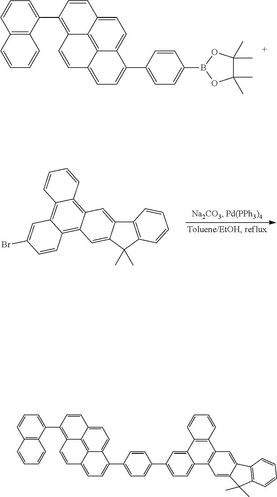
- FALGUHUNCWKARY-UHFFFAOYSA-N CC1(C)C2=CC3=C(C=C2C2=C1C=CC=C2)C1=C(C=CC=C1)C1=CC(C2=CC=C(C4=CC=C5/C=C\C6=C(C7=CC=CC8=C7C=CC=C8)C=CC7=CC=C4C5=C76)C=C2)=CC=C13.CC1(C)C2=CC3=C4C=CC(Br)=CC4=C4C=CC=CC4=C3C=C2C2=C1/C=C\C=C/2.CC1(C)OB(C2=CC=C(C3=CC=C4/C=C\C5=C(C6=CC=CC7=C6C=CC=C7)C=CC6=CC=C3C4=C65)C=C2)OC1(C)C Chemical compound CC1(C)C2=CC3=C(C=C2C2=C1C=CC=C2)C1=C(C=CC=C1)C1=CC(C2=CC=C(C4=CC=C5/C=C\C6=C(C7=CC=CC8=C7C=CC=C8)C=CC7=CC=C4C5=C76)C=C2)=CC=C13.CC1(C)C2=CC3=C4C=CC(Br)=CC4=C4C=CC=CC4=C3C=C2C2=C1/C=C\C=C/2.CC1(C)OB(C2=CC=C(C3=CC=C4/C=C\C5=C(C6=CC=CC7=C6C=CC=C7)C=CC6=CC=C3C4=C65)C=C2)OC1(C)C FALGUHUNCWKARY-UHFFFAOYSA-N 0.000 description 1
- WOYZTLGNXVLFKD-UHFFFAOYSA-N CC1(C)C2=CC3=C(C=C2C2=C1C=CC=C2)C1=C(C=CC=C1)C1=CC(C2=CC=C(C4=CC=C5/C=C\C6=C(C7=CC=CC=C7)C=CC7=CC=C4C5=C76)C=C2)=CC=C13.CC1(C)C2=CC3=C4C=CC(Br)=CC4=C4C=CC=CC4=C3C=C2C2=C1/C=C\C=C/2.CC1(C)OB(C2=CC=C(C3=CC=C4/C=C\C5=C(C6=CC=CC=C6)C=CC6=CC=C3C4=C65)C=C2)OC1(C)C Chemical compound CC1(C)C2=CC3=C(C=C2C2=C1C=CC=C2)C1=C(C=CC=C1)C1=CC(C2=CC=C(C4=CC=C5/C=C\C6=C(C7=CC=CC=C7)C=CC7=CC=C4C5=C76)C=C2)=CC=C13.CC1(C)C2=CC3=C4C=CC(Br)=CC4=C4C=CC=CC4=C3C=C2C2=C1/C=C\C=C/2.CC1(C)OB(C2=CC=C(C3=CC=C4/C=C\C5=C(C6=CC=CC=C6)C=CC6=CC=C3C4=C65)C=C2)OC1(C)C WOYZTLGNXVLFKD-UHFFFAOYSA-N 0.000 description 1
- ZSOLXGKMWJQWDT-UHFFFAOYSA-N CC1(C)C2=CC3=C4C=CC(C5=C6C=CC=CC6=C(C6=CC=C(C7=CC=CC8=C7C=CC=C8)C=C6)C6=C5C=CC=C6)=CC4=C4C=CC=CC4=C3C=C2C2=C1C=CC=C2.CC1(C)C2=CC3=C4C=CC(C5=CC=C(C6=CC=C7/C=C\C8=C9C(=CC=C8C8=C%10C=CC=CC%10=CC=C8)C=CC6=C79)C=C5)=CC4=C4C=CC=CC4=C3C=C2C2=C1C=CC=C2.CC1(C)C2=CC3=C4C=CC(C5=CC=C(C6=CC=C7/C=C\C8=C9C(=CC=C8C8=CC=CC=C8)C=CC6=C79)C=C5)=CC4=C4C=CC=CC4=C3C=C2C2=C1C=CC=C2 Chemical compound CC1(C)C2=CC3=C4C=CC(C5=C6C=CC=CC6=C(C6=CC=C(C7=CC=CC8=C7C=CC=C8)C=C6)C6=C5C=CC=C6)=CC4=C4C=CC=CC4=C3C=C2C2=C1C=CC=C2.CC1(C)C2=CC3=C4C=CC(C5=CC=C(C6=CC=C7/C=C\C8=C9C(=CC=C8C8=C%10C=CC=CC%10=CC=C8)C=CC6=C79)C=C5)=CC4=C4C=CC=CC4=C3C=C2C2=C1C=CC=C2.CC1(C)C2=CC3=C4C=CC(C5=CC=C(C6=CC=C7/C=C\C8=C9C(=CC=C8C8=CC=CC=C8)C=CC6=C79)C=C5)=CC4=C4C=CC=CC4=C3C=C2C2=C1C=CC=C2 ZSOLXGKMWJQWDT-UHFFFAOYSA-N 0.000 description 1
- LWOXSCSSWQTSQA-UHFFFAOYSA-N CC1(C)C2=CC=CC=C2C2=C1/C=C(B(O)O)\C=C/2.CC1(C)C2=CC=CC=C2C2=C1/C=C(C1=CC=C([N+](=O)[O-])C=C1C1=CC=CC=C1)\C=C/2.O=[N+]([O-])C1=CC(C2=CC=CC=C2)=C(Br)C=C1 Chemical compound CC1(C)C2=CC=CC=C2C2=C1/C=C(B(O)O)\C=C/2.CC1(C)C2=CC=CC=C2C2=C1/C=C(C1=CC=C([N+](=O)[O-])C=C1C1=CC=CC=C1)\C=C/2.O=[N+]([O-])C1=CC(C2=CC=CC=C2)=C(Br)C=C1 LWOXSCSSWQTSQA-UHFFFAOYSA-N 0.000 description 1
- XIJOKBGWZJUKCE-UHFFFAOYSA-N CC1(C)C2=CC=CC=C2C2=C1/C=C(C1=CC=C(Br)C=C1C1=CC=CC=C1)\C=C/2.CC1(C)C2=CC=CC=C2C2=C1/C=C(C1=CC=C(N)C=C1C1=CC=CC=C1)\C=C/2 Chemical compound CC1(C)C2=CC=CC=C2C2=C1/C=C(C1=CC=C(Br)C=C1C1=CC=CC=C1)\C=C/2.CC1(C)C2=CC=CC=C2C2=C1/C=C(C1=CC=C(N)C=C1C1=CC=CC=C1)\C=C/2 XIJOKBGWZJUKCE-UHFFFAOYSA-N 0.000 description 1
- ZRUQJLFZBKRYBN-UHFFFAOYSA-K CC1(C)C2=CC=CC=C2C2=C1/C=C(C1=CC=C(Br)C=C1C1=CC=CC=C1)\C=C/2.CC1(C)C2=CC=CC=C2C2=C1/C=C1/C3=CC=C(Br)C=C3C3=CC=CC=C3/C1=C/2.Cl[Fe](Cl)Cl Chemical compound CC1(C)C2=CC=CC=C2C2=C1/C=C(C1=CC=C(Br)C=C1C1=CC=CC=C1)\C=C/2.CC1(C)C2=CC=CC=C2C2=C1/C=C1/C3=CC=C(Br)C=C3C3=CC=CC=C3/C1=C/2.Cl[Fe](Cl)Cl ZRUQJLFZBKRYBN-UHFFFAOYSA-K 0.000 description 1
- CARPUIVYZOSSLC-UHFFFAOYSA-N CC1(C)C2=CC=CC=C2C2=C1/C=C(C1=CC=C(N)C=C1C1=CC=CC=C1)\C=C/2.CC1(C)C2=CC=CC=C2C2=C1/C=C(C1=CC=C([N+](=O)[O-])C=C1C1=CC=CC=C1)\C=C/2 Chemical compound CC1(C)C2=CC=CC=C2C2=C1/C=C(C1=CC=C(N)C=C1C1=CC=CC=C1)\C=C/2.CC1(C)C2=CC=CC=C2C2=C1/C=C(C1=CC=C([N+](=O)[O-])C=C1C1=CC=CC=C1)\C=C/2 CARPUIVYZOSSLC-UHFFFAOYSA-N 0.000 description 1
- MGHZASLHPOVLJG-UHFFFAOYSA-N CC1(C)C2=CC=CC=C2C2=C1/C=C1/C3=CC=C(Br)C=C3C3=CC=CC=C3/C1=C/2.CC1(C)C2=CC=CC=C2C2=C1C=C1C3=CC=C(C4=C5C=CC=CC5=C(C5=CC=C(C6=CC=CC7=C6C=CC=C7)C=C5)C5=C4C=CC=C5)C=C3C3=CC=CC=C3C1=C2.OB(O)C1=C2C=CC=CC2=C(C2=CC=C(C3=CC=CC4=C3C=CC=C4)C=C2)C2=C1C=CC=C2 Chemical compound CC1(C)C2=CC=CC=C2C2=C1/C=C1/C3=CC=C(Br)C=C3C3=CC=CC=C3/C1=C/2.CC1(C)C2=CC=CC=C2C2=C1C=C1C3=CC=C(C4=C5C=CC=CC5=C(C5=CC=C(C6=CC=CC7=C6C=CC=C7)C=C5)C5=C4C=CC=C5)C=C3C3=CC=CC=C3C1=C2.OB(O)C1=C2C=CC=CC2=C(C2=CC=C(C3=CC=CC4=C3C=CC=C4)C=C2)C2=C1C=CC=C2 MGHZASLHPOVLJG-UHFFFAOYSA-N 0.000 description 1
- DAYCLRPCQULVQM-UHFFFAOYSA-N CC1(C)C2=CC=CC=C2C2=C1/C=C1/C3=CC=C(Br)C=C3C3=CC=CC=C3/C1=C/2.CC1(C)C2=CC=CC=C2C2=C1C=C1C3=CC=C(C4=CC=C(C5=C6C=CC=CC6=C(C6=CC=C7C=CC=CC7=C6)C6=C5C=CC=C6)C=C4)C=C3C3=CC=CC=C3C1=C2.OB(O)C1=CC=C(C2=C3C=CC=CC3=C(C3=CC=C4/C=C\C=C/C4=C3)C3=CC=CC=C32)C=C1 Chemical compound CC1(C)C2=CC=CC=C2C2=C1/C=C1/C3=CC=C(Br)C=C3C3=CC=CC=C3/C1=C/2.CC1(C)C2=CC=CC=C2C2=C1C=C1C3=CC=C(C4=CC=C(C5=C6C=CC=CC6=C(C6=CC=C7C=CC=CC7=C6)C6=C5C=CC=C6)C=C4)C=C3C3=CC=CC=C3C1=C2.OB(O)C1=CC=C(C2=C3C=CC=CC3=C(C3=CC=C4/C=C\C=C/C4=C3)C3=CC=CC=C32)C=C1 DAYCLRPCQULVQM-UHFFFAOYSA-N 0.000 description 1
- ZZFCEFHWIXRBEP-UHFFFAOYSA-N CC1(C)C2=CC=CC=C2C2=C1C=C1C3=CC=C(Br)C=C3C3=CC=CC=C3C1=C2.CC1(C)C2=CC=CC=C2C2=C1C=C1C3=CC=C(C4=C5C=CC=CC5=C(C5=CC=C6C=CC=CC6=C5)C5=C4C=CC=C5)C=C3C3=CC=CC=C3C1=C2.OB(O)C1=C2C=CC=CC2=C(C2=CC=C3/C=C\C=C/C3=C2)C2=CC=CC=C21 Chemical compound CC1(C)C2=CC=CC=C2C2=C1C=C1C3=CC=C(Br)C=C3C3=CC=CC=C3C1=C2.CC1(C)C2=CC=CC=C2C2=C1C=C1C3=CC=C(C4=C5C=CC=CC5=C(C5=CC=C6C=CC=CC6=C5)C5=C4C=CC=C5)C=C3C3=CC=CC=C3C1=C2.OB(O)C1=C2C=CC=CC2=C(C2=CC=C3/C=C\C=C/C3=C2)C2=CC=CC=C21 ZZFCEFHWIXRBEP-UHFFFAOYSA-N 0.000 description 1
- YJGFGVUSCDUTKE-UHFFFAOYSA-N NC1=C(C2=CC=CC=C2)C=C([N+](=O)[O-])C=C1.O=[N+]([O-])C1=CC(C2=CC=CC=C2)=C(Br)C=C1 Chemical compound NC1=C(C2=CC=CC=C2)C=C([N+](=O)[O-])C=C1.O=[N+]([O-])C1=CC(C2=CC=CC=C2)=C(Br)C=C1 YJGFGVUSCDUTKE-UHFFFAOYSA-N 0.000 description 1
Images


Classifications
-
- H01L51/0056—
-
- C—CHEMISTRY; METALLURGY
- C07—ORGANIC CHEMISTRY
- C07C—ACYCLIC OR CARBOCYCLIC COMPOUNDS
- C07C13/00—Cyclic hydrocarbons containing rings other than, or in addition to, six-membered aromatic rings
- C07C13/28—Polycyclic hydrocarbons or acyclic hydrocarbon derivatives thereof
- C07C13/32—Polycyclic hydrocarbons or acyclic hydrocarbon derivatives thereof with condensed rings
- C07C13/62—Polycyclic hydrocarbons or acyclic hydrocarbon derivatives thereof with condensed rings with more than three condensed rings
-
- C—CHEMISTRY; METALLURGY
- C09—DYES; PAINTS; POLISHES; NATURAL RESINS; ADHESIVES; COMPOSITIONS NOT OTHERWISE PROVIDED FOR; APPLICATIONS OF MATERIALS NOT OTHERWISE PROVIDED FOR
- C09B—ORGANIC DYES OR CLOSELY-RELATED COMPOUNDS FOR PRODUCING DYES, e.g. PIGMENTS; MORDANTS; LAKES
- C09B1/00—Dyes with anthracene nucleus not condensed with any other ring
-
- C—CHEMISTRY; METALLURGY
- C09—DYES; PAINTS; POLISHES; NATURAL RESINS; ADHESIVES; COMPOSITIONS NOT OTHERWISE PROVIDED FOR; APPLICATIONS OF MATERIALS NOT OTHERWISE PROVIDED FOR
- C09B—ORGANIC DYES OR CLOSELY-RELATED COMPOUNDS FOR PRODUCING DYES, e.g. PIGMENTS; MORDANTS; LAKES
- C09B57/00—Other synthetic dyes of known constitution
- C09B57/001—Pyrene dyes
-
- C—CHEMISTRY; METALLURGY
- C09—DYES; PAINTS; POLISHES; NATURAL RESINS; ADHESIVES; COMPOSITIONS NOT OTHERWISE PROVIDED FOR; APPLICATIONS OF MATERIALS NOT OTHERWISE PROVIDED FOR
- C09K—MATERIALS FOR MISCELLANEOUS APPLICATIONS, NOT PROVIDED FOR ELSEWHERE
- C09K11/00—Luminescent materials, e.g. electroluminescent or chemiluminescent
- C09K11/02—Use of particular materials as binders, particle coatings or suspension media therefor
- C09K11/025—Use of particular materials as binders, particle coatings or suspension media therefor non-luminescent particle coatings or suspension media
-
- C—CHEMISTRY; METALLURGY
- C09—DYES; PAINTS; POLISHES; NATURAL RESINS; ADHESIVES; COMPOSITIONS NOT OTHERWISE PROVIDED FOR; APPLICATIONS OF MATERIALS NOT OTHERWISE PROVIDED FOR
- C09K—MATERIALS FOR MISCELLANEOUS APPLICATIONS, NOT PROVIDED FOR ELSEWHERE
- C09K11/00—Luminescent materials, e.g. electroluminescent or chemiluminescent
- C09K11/06—Luminescent materials, e.g. electroluminescent or chemiluminescent containing organic luminescent materials
-
- H01L51/0052—
-
- H01L51/0054—
-
- H01L51/0057—
-
- H01L51/0058—
-
- H01L51/0067—
-
- H01L51/0072—
-
- H01L51/0074—
-
- H—ELECTRICITY
- H05—ELECTRIC TECHNIQUES NOT OTHERWISE PROVIDED FOR
- H05B—ELECTRIC HEATING; ELECTRIC LIGHT SOURCES NOT OTHERWISE PROVIDED FOR; CIRCUIT ARRANGEMENTS FOR ELECTRIC LIGHT SOURCES, IN GENERAL
- H05B33/00—Electroluminescent light sources
- H05B33/12—Light sources with substantially two-dimensional [2D] radiating surfaces
- H05B33/20—Light sources with substantially two-dimensional [2D] radiating surfaces characterised by the chemical or physical composition or the arrangement of the material in which the electroluminescent material is embedded
-
- H—ELECTRICITY
- H10—SEMICONDUCTOR DEVICES; ELECTRIC SOLID-STATE DEVICES NOT OTHERWISE PROVIDED FOR
- H10K—ORGANIC ELECTRIC SOLID-STATE DEVICES
- H10K85/00—Organic materials used in the body or electrodes of devices covered by this subclass
- H10K85/60—Organic compounds having low molecular weight
- H10K85/615—Polycyclic condensed aromatic hydrocarbons, e.g. anthracene
- H10K85/622—Polycyclic condensed aromatic hydrocarbons, e.g. anthracene containing four rings, e.g. pyrene
-
- H—ELECTRICITY
- H10—SEMICONDUCTOR DEVICES; ELECTRIC SOLID-STATE DEVICES NOT OTHERWISE PROVIDED FOR
- H10K—ORGANIC ELECTRIC SOLID-STATE DEVICES
- H10K85/00—Organic materials used in the body or electrodes of devices covered by this subclass
- H10K85/60—Organic compounds having low molecular weight
- H10K85/615—Polycyclic condensed aromatic hydrocarbons, e.g. anthracene
- H10K85/624—Polycyclic condensed aromatic hydrocarbons, e.g. anthracene containing six or more rings
-
- H—ELECTRICITY
- H10—SEMICONDUCTOR DEVICES; ELECTRIC SOLID-STATE DEVICES NOT OTHERWISE PROVIDED FOR
- H10K—ORGANIC ELECTRIC SOLID-STATE DEVICES
- H10K85/00—Organic materials used in the body or electrodes of devices covered by this subclass
- H10K85/60—Organic compounds having low molecular weight
- H10K85/615—Polycyclic condensed aromatic hydrocarbons, e.g. anthracene
- H10K85/625—Polycyclic condensed aromatic hydrocarbons, e.g. anthracene containing at least one aromatic ring having 7 or more carbon atoms, e.g. azulene
-
- H—ELECTRICITY
- H10—SEMICONDUCTOR DEVICES; ELECTRIC SOLID-STATE DEVICES NOT OTHERWISE PROVIDED FOR
- H10K—ORGANIC ELECTRIC SOLID-STATE DEVICES
- H10K85/00—Organic materials used in the body or electrodes of devices covered by this subclass
- H10K85/60—Organic compounds having low molecular weight
- H10K85/615—Polycyclic condensed aromatic hydrocarbons, e.g. anthracene
- H10K85/626—Polycyclic condensed aromatic hydrocarbons, e.g. anthracene containing more than one polycyclic condensed aromatic rings, e.g. bis-anthracene
-
- H—ELECTRICITY
- H10—SEMICONDUCTOR DEVICES; ELECTRIC SOLID-STATE DEVICES NOT OTHERWISE PROVIDED FOR
- H10K—ORGANIC ELECTRIC SOLID-STATE DEVICES
- H10K85/00—Organic materials used in the body or electrodes of devices covered by this subclass
- H10K85/60—Organic compounds having low molecular weight
- H10K85/649—Aromatic compounds comprising a hetero atom
- H10K85/654—Aromatic compounds comprising a hetero atom comprising only nitrogen as heteroatom
-
- H—ELECTRICITY
- H10—SEMICONDUCTOR DEVICES; ELECTRIC SOLID-STATE DEVICES NOT OTHERWISE PROVIDED FOR
- H10K—ORGANIC ELECTRIC SOLID-STATE DEVICES
- H10K85/00—Organic materials used in the body or electrodes of devices covered by this subclass
- H10K85/60—Organic compounds having low molecular weight
- H10K85/649—Aromatic compounds comprising a hetero atom
- H10K85/657—Polycyclic condensed heteroaromatic hydrocarbons
- H10K85/6572—Polycyclic condensed heteroaromatic hydrocarbons comprising only nitrogen in the heteroaromatic polycondensed ring system, e.g. phenanthroline or carbazole
-
- H—ELECTRICITY
- H10—SEMICONDUCTOR DEVICES; ELECTRIC SOLID-STATE DEVICES NOT OTHERWISE PROVIDED FOR
- H10K—ORGANIC ELECTRIC SOLID-STATE DEVICES
- H10K85/00—Organic materials used in the body or electrodes of devices covered by this subclass
- H10K85/60—Organic compounds having low molecular weight
- H10K85/649—Aromatic compounds comprising a hetero atom
- H10K85/657—Polycyclic condensed heteroaromatic hydrocarbons
- H10K85/6576—Polycyclic condensed heteroaromatic hydrocarbons comprising only sulfur in the heteroaromatic polycondensed ring system, e.g. benzothiophene
-
- C—CHEMISTRY; METALLURGY
- C07—ORGANIC CHEMISTRY
- C07C—ACYCLIC OR CARBOCYCLIC COMPOUNDS
- C07C2603/00—Systems containing at least three condensed rings
- C07C2603/02—Ortho- or ortho- and peri-condensed systems
- C07C2603/04—Ortho- or ortho- and peri-condensed systems containing three rings
- C07C2603/22—Ortho- or ortho- and peri-condensed systems containing three rings containing only six-membered rings
- C07C2603/24—Anthracenes; Hydrogenated anthracenes
-
- C—CHEMISTRY; METALLURGY
- C07—ORGANIC CHEMISTRY
- C07C—ACYCLIC OR CARBOCYCLIC COMPOUNDS
- C07C2603/00—Systems containing at least three condensed rings
- C07C2603/02—Ortho- or ortho- and peri-condensed systems
- C07C2603/04—Ortho- or ortho- and peri-condensed systems containing three rings
- C07C2603/22—Ortho- or ortho- and peri-condensed systems containing three rings containing only six-membered rings
- C07C2603/26—Phenanthrenes; Hydrogenated phenanthrenes
-
- C—CHEMISTRY; METALLURGY
- C07—ORGANIC CHEMISTRY
- C07C—ACYCLIC OR CARBOCYCLIC COMPOUNDS
- C07C2603/00—Systems containing at least three condensed rings
- C07C2603/02—Ortho- or ortho- and peri-condensed systems
- C07C2603/40—Ortho- or ortho- and peri-condensed systems containing four condensed rings
- C07C2603/42—Ortho- or ortho- and peri-condensed systems containing four condensed rings containing only six-membered rings
- C07C2603/48—Chrysenes; Hydrogenated chrysenes
-
- C—CHEMISTRY; METALLURGY
- C07—ORGANIC CHEMISTRY
- C07C—ACYCLIC OR CARBOCYCLIC COMPOUNDS
- C07C2603/00—Systems containing at least three condensed rings
- C07C2603/02—Ortho- or ortho- and peri-condensed systems
- C07C2603/40—Ortho- or ortho- and peri-condensed systems containing four condensed rings
- C07C2603/42—Ortho- or ortho- and peri-condensed systems containing four condensed rings containing only six-membered rings
- C07C2603/50—Pyrenes; Hydrogenated pyrenes
-
- C—CHEMISTRY; METALLURGY
- C07—ORGANIC CHEMISTRY
- C07C—ACYCLIC OR CARBOCYCLIC COMPOUNDS
- C07C2603/00—Systems containing at least three condensed rings
- C07C2603/02—Ortho- or ortho- and peri-condensed systems
- C07C2603/54—Ortho- or ortho- and peri-condensed systems containing more than five condensed rings
-
- H01L2251/5376—
-
- H01L2251/552—
-
- H01L51/5004—
-
- H01L51/5012—
-
- H01L51/5016—
-
- H01L51/5072—
-
- H01L51/5076—
-
- H—ELECTRICITY
- H10—SEMICONDUCTOR DEVICES; ELECTRIC SOLID-STATE DEVICES NOT OTHERWISE PROVIDED FOR
- H10K—ORGANIC ELECTRIC SOLID-STATE DEVICES
- H10K2101/00—Properties of the organic materials covered by group H10K85/00
- H10K2101/10—Triplet emission
-
- H—ELECTRICITY
- H10—SEMICONDUCTOR DEVICES; ELECTRIC SOLID-STATE DEVICES NOT OTHERWISE PROVIDED FOR
- H10K—ORGANIC ELECTRIC SOLID-STATE DEVICES
- H10K2101/00—Properties of the organic materials covered by group H10K85/00
- H10K2101/27—Combination of fluorescent and phosphorescent emission
-
- H—ELECTRICITY
- H10—SEMICONDUCTOR DEVICES; ELECTRIC SOLID-STATE DEVICES NOT OTHERWISE PROVIDED FOR
- H10K—ORGANIC ELECTRIC SOLID-STATE DEVICES
- H10K2101/00—Properties of the organic materials covered by group H10K85/00
- H10K2101/30—Highest occupied molecular orbital [HOMO], lowest unoccupied molecular orbital [LUMO] or Fermi energy values
-
- H—ELECTRICITY
- H10—SEMICONDUCTOR DEVICES; ELECTRIC SOLID-STATE DEVICES NOT OTHERWISE PROVIDED FOR
- H10K—ORGANIC ELECTRIC SOLID-STATE DEVICES
- H10K2101/00—Properties of the organic materials covered by group H10K85/00
- H10K2101/40—Interrelation of parameters between multiple constituent active layers or sublayers, e.g. HOMO values in adjacent layers
-
- H—ELECTRICITY
- H10—SEMICONDUCTOR DEVICES; ELECTRIC SOLID-STATE DEVICES NOT OTHERWISE PROVIDED FOR
- H10K—ORGANIC ELECTRIC SOLID-STATE DEVICES
- H10K50/00—Organic light-emitting devices
- H10K50/10—OLEDs or polymer light-emitting diodes [PLED]
- H10K50/11—OLEDs or polymer light-emitting diodes [PLED] characterised by the electroluminescent [EL] layers
-
- H—ELECTRICITY
- H10—SEMICONDUCTOR DEVICES; ELECTRIC SOLID-STATE DEVICES NOT OTHERWISE PROVIDED FOR
- H10K—ORGANIC ELECTRIC SOLID-STATE DEVICES
- H10K50/00—Organic light-emitting devices
- H10K50/10—OLEDs or polymer light-emitting diodes [PLED]
- H10K50/14—Carrier transporting layers
- H10K50/16—Electron transporting layers
- H10K50/165—Electron transporting layers comprising dopants
Definitions
- the present invention generally relates to a compound and organic electroluminescent (herein referred to as organic EL) device using the compound. More specifically, the present invention relates to the compound having general formula(I), an organic EL device employing the compound as fluorescent emitting host or phosphorescent emitting host.
- organic EL organic electroluminescent
- Organic electroluminescent is a light-emitting diode (LED) in which the emissive layer is a film made by organic compounds which emits light in response to an electric current.
- the emissive layer of organic compound is sandwiched between two electrodes.
- Organic EL is applied in flat panel displays due to their high illumination, low weight, ultra-thin profile, self-illumination without back light, low power consumption, wide viewing angle, high contrast, simple fabrication methods and rapid response time.
- the first diode device was reported by Ching W. Tang and Steven Van Slyke at Eastman Kodak in 1987.
- the device used a two-layer structure with separate hole transporting and electron transporting layers resulted in reduction in operating voltage and improvement of the efficiency, that led to the current era of organic EL research and device production.
- organic EL device is composed of layers of organic materials situated between two electrodes, which include a hole transporting layer (HTL), an emitting layer (EML), an electron transporting layer (ETL).
- HTL hole transporting layer
- EML emitting layer
- ETL electron transporting layer
- the basic mechanism of organic EL involves the injection of the carrier, transport, recombination of carriers and exciton formed to emit light.
- an external voltage is applied to an organic EL device, electrons and holes are injected from a cathode and an anode, respectively, electrons will be injected from a cathode into a LUMO (lowest unoccupied molecular orbital) and holes will be injected from an anode into a HOMO (highest occupied molecular orbital).
- an exciton When the electrons recombine with holes in the emitting layer, excitons are formed and then emit light.
- an exciton When luminescent molecules absorb energy to achieve an excited state, an exciton may either be in a singlet state or a triplet state depending on how the spins of the electron and hole have been combined. 75% of the excitons form by recombination of electrons and holes to achieve a triplet excited state. Decay from triplet states is spin forbidden, Thus, a fluorescence electroluminescent device has only 25% internal quantum efficiency.
- phosphorescent organic EL device make use of spin-orbit interactions to facilitate intersystem crossing between singlet and triplet states, thus obtaining emission from both singlet and triplet states and the internal quantum efficiency of electroluminescent devices from 25% to 100%.
- TADF thermally activated delayed fluorescence
- the organic EL utilizes both triplet and singlet excitons.
- the phosphorescent organic EL generally need an additional hole blocking layer (HBL) between the emitting layer (EML) and the electron transporting layer (ETL) or the electron transporting layer with hole blocking ability instead of typical ETL.
- HBL hole blocking layer
- EML emitting layer
- ETL electron transporting layer
- HBETL electron transporting layer
- the hole blocking materials must have HOMO (highest occupied molecular orbital) and LUMO (lowest unoccupied molecular orbital) energy levels suitable to block hole transport from the EML to the ETL and to pass electrons from the ETL to the EML, in addition, the good thermal and electrochemical stability of the phosphorescent emitting host material are also needed.
- HOMO highest occupied molecular orbital
- LUMO lowest unoccupied molecular orbital
- the present invention has the objective of resolving such problems of the prior-art such as US20140131664A1, US20140175384A1 and US20140209866A1.
- the prior compounds used diaryl group linked to the position 12 of indenotriphenylene core.
- the present invention utilize a diaryl substituted arylene group linked to the position 5, 6, 7 and 8 of indenotriphenylene core and offering a light emitting device which is excellent in its thermal stability, high luminance efficiency, high luminance and long half-life time than the prior materials.
- a compound can use as fluorescent emitting host or phosphorescent emitting host for organic EL device.
- the compound can overcome the drawbacks of the prior materials such as US20140131664A1, US20140175384A1 and US20140209866A1 like as lower efficiency, half-lifetime and higher power consumption.
- An object of the present invention is to provide the compound which can be used as fluorescent emitting host or phosphorescent emitting host for organic EL device.
- the present invention has the economic advantages for industrial practice. Accordingly the present invention, the compound which can be used for organic EL device is disclosed. The mentioned the compound is represented by the following formula(I)
- A represents a phenyl group and a substituted or unsubstituted fused ring hydrocarbon units with two to four rings group
- L represents a single bond or a substituted or unsubstituted divalent arylene group having 6 to 30 ring carbon atoms
- Ar 1 and Ar 2 independently are selected from the group consisting of a substituted or unsubstituted phenyl group, a substituted or unsubstituted naphthyl group, a substituted or unsubstituted anthracenyl group, a substituted or unsubstituted phenanthrenyl group, a substituted or unsubstituted pyrenyl group and a substituted or unsubstituted chrysenyl group;
- R 1 to R 3 independently selected from the group consisting of a hydrogen atom, a substituted or unsubstituted alkyl group having 1 to 20 carbon atoms, a substituted or unsubstituted
- FIG. 1 show one example of organic EL device in the present invention.
- 6 is transparent electrode
- 13 is metal electrode
- 7 is hole injection layer which is deposited onto 6
- 8 is hole transport layer which is deposited onto 7
- 9 is fluorescent or phosphorescent emitting layer which is deposited onto 8
- 10 is hole blocking layer which is deposited onto 9
- 11 is electron transport layer which is deposited onto 10
- 12 is electron injection layer which is deposited on to 11.
- the compound which can be used as fluorescent emitting host or phosphorescent emitting host for organic EL device are disclosed.
- the mentioned compound are represented by the following formula(I)
- A represents a phenyl group and a substituted or unsubstituted fused ring hydrocarbon units with two to four rings group
- L represents a single bond or a substituted or unsubstituted divalent arylene group having 6 to 30 ring carbon atoms
- Ar 1 and Ar 2 independently are selected from the group consisting of a substituted or unsubstituted phenyl group, a substituted or unsubstituted naphthyl group, a substituted or unsubstituted anthracenyl group, a substituted or unsubstituted phenanthrenyl group, a substituted or unsubstituted pyrenyl group and a substituted or unsubstituted chrysenyl group;
- R 1 to R 3 independently selected from the group consisting of a hydrogen atom, a substituted or unsubstituted alkyl group having 1 to 20 carbon atoms, a substituted or unsubstituted
- Ar 1 and Ar 2 independently are selected from the group consisting of a substituted or unsubstituted phenyl group, a substituted or unsubstituted naphthyl group, a substituted or unsubstituted anthracenyl group, a substituted or unsubstituted phenanthrenyl group, a substituted or unsubstituted pyrenyl group and a substituted or unsubstituted chrysenyl group; R 1 to R 3 independently selected from the group consisting of a hydrogen atom, a substituted or unsubstituted alkyl group having 1 to 20 carbon atoms, a substituted or unsubstituted aryl group having 6 to 30 carbon atoms, a substituted or unsubstituted aralkyl group having 6 to 30 carbon atoms and
- EXAMPLE 1 ⁇ 5 show the preparation for some EXAMPLES of the compound in the present invention.
- EXAMPLE 6 ⁇ 7 show the fabrication of organic EL device and I-V-B, life time of organic EL device testing report.
- ITO-coated glasses with 9 ⁇ 12 ohm/square in resistance and 120 ⁇ 160 nm in thickness are provided (hereinafter ITO substrate) and cleaned in a number of cleaning steps in an ultrasonic bath (e.g. detergent, deionized water). Before vapor deposition of the organic layers, cleaned ITO substrates are further treated by UV and ozone. All pre-treatment processes for ITO substrate are under clean room (class 100).
- an ultrasonic bath e.g. detergent, deionized water
- These organic layers are applied onto the ITO substrate in order by vapor deposition in a high-vacuum unit (10 ⁇ 7 Torr), such as: resistively heated quartz boats.
- a high-vacuum unit 10 ⁇ 7 Torr
- the thickness of the respective layer and the vapor deposition rate (0.1 ⁇ 0.3 nm/sec) are precisely monitored or set with the aid of a quartz-crystal monitor.
- individual layers can consist of more than one compound, i.e. in general a host material doped with a dopant material. This is achieved by co-vaporization from two or more sources.
- Dipyrazino[2,3-f: 2,3-]quinoxaline-2,3,6,7,10,11-hexacarbonitrile (HAT-CN) is used as hole injection layer in this organic EL device.
- N,N-Bis(naphthalene-1-yl)-N,N-bis(phenyl)-benzidine (NPB) is most widely used as the hole transporting layer.
- 2-(10,10-dimethyl-10H-indeno[2,1-b]triphenylen-13-yl)-9-phenyl-1,10-phenanthroline is used as electron transporting material (ET1) to co-deposit with 5% Li
- Tris(2-phenylpyridinato)iridium(III) (D2) is used as phosphorescent dopant.
- 4-(10,10-dimethyl-10H-indeno[2,1-b] triphenylen-13-yl)dibenzo[b,d]thiophene (H1) is used as hole blocking material or emitting host in organic phosphorescent EL device.
- the prior art of OLED materials for producing standard organic EL device control and comparable material in this invention shown its chemical structure as follows:
- a typical organic EL device consists of low work function metals, such as Al, Mg, Ca, Li and K, as the cathode by thermal evaporation, and the low work function metals can help electrons injecting the electron transporting layer from cathode.
- the low work function metals can help electrons injecting the electron transporting layer from cathode.
- a thin-film electron injecting layer is introduced between the cathode and the electron transporting layer.
- Conventional materials of electron injecting layer are metal halide or metal oxide with low work function, such as: LiF, LiQ, MgO, or Li 2 O.
- EL spectra and CIE coordination are measured by using a PR650 spectra scan spectrometer.
- the current/voltage, luminescence/voltage and yield/voltage characteristics are taken with a Keithley 2400 programmable voltage-current source.
- the above-mentioned apparatuses are operated at room temperature (about 25° C.) and under atmospheric pressure.
- fluorescent blue-emitting organic EL device having the following device structure I and II was produced (See FIG. 1 ).
- Device I ITO/HAT-CN (20 nm)/NPB (130 nm)/fluorescent host doped 5% D1 (30 nm)/ET2 (10 nm)/ETM doped 5% Li (35 nm)/Al (160 nm).
- ITO/HAT-CN (20 nm)/NPB (130 nm)/fluorescent host doped 5% D1 (30 nm)/ET2 (10 nm)/ETM co-deposit 50% LiQ (35 nm)/LiQ (1 nm)/Al (160 nm).
- the I-V-B (at 1000 nits) and half-life time of fluorescent blue-emitting organic EL device testing report as Table 1 and Table 2, The half-life time is defined that the initial luminance of 1000 cd/m 2 has dropped to half.
- phosphorescent emitting organic EL device having the following device structures are produced (See FIG. 1 .): ITO/HAT-CN (20 nm)/NPB (130 nm)/phosphorescent host (PHhost)+12% D2 (30 nm)/H1 (15 nm)/ET2 co-deposit 50% LiQ (40 nm)/LiQ (1 nm)/Al (160 nm).
- the I-V-B (at 1000 nits) and half-life time of phosphorescent emitting organic EL device testing report as Table 3. The half-life time is defined that the initial luminance of 3000 cd/m 2 has dropped to half.
- organic EL device test report see Table 1 to Table 3
- H1 hole blocking layer or phosphorescent host
- ET1 electron transporting layer
- the present invention discloses a compound which can be used for organic EL device is disclosed. More specifically, an organic EL device employing the compound as fluorescent emitting host, phosphorescent emitting host.
- the mentioned compound are represented by the following formula(I)
- A represents a phenyl group and a substituted or unsubstituted fused ring hydrocarbon units with two to four rings group
- L represents a single bond or a substituted or unsubstituted divalent arylene group having 6 to 30 ring carbon atoms
- Ar 1 and Ar 2 independently are selected from the group consisting of a substituted or unsubstituted phenyl group, a substituted or unsubstituted naphthyl group, a substituted or unsubstituted anthracenyl group, a substituted or unsubstituted phenanthrenyl group, a substituted or unsubstituted pyrenyl group and a substituted or unsubstituted chrysenyl group;
- R 1 to R 3 independently selected from the group consisting of a hydrogen atom, a substituted or unsubstituted alkyl group having 1 to 20 carbon atoms, a substituted or unsubstituted
Landscapes
- Chemical & Material Sciences (AREA)
- Organic Chemistry (AREA)
- Engineering & Computer Science (AREA)
- Materials Engineering (AREA)
- Physics & Mathematics (AREA)
- Spectroscopy & Molecular Physics (AREA)
- Electroluminescent Light Sources (AREA)
Abstract
Description

wherein A represents a phenyl group and a substituted or unsubstituted fused ring hydrocarbon units with two to four rings group, L represents a single bond or a substituted or unsubstituted divalent arylene group having 6 to 30 ring carbon atoms, Ar1 and Ar2 independently are selected from the group consisting of a substituted or unsubstituted phenyl group, a substituted or unsubstituted naphthyl group, a substituted or unsubstituted anthracenyl group, a substituted or unsubstituted phenanthrenyl group, a substituted or unsubstituted pyrenyl group and a substituted or unsubstituted chrysenyl group; R1 to R3 independently selected from the group consisting of a hydrogen atom, a substituted or unsubstituted alkyl group having 1 to 20 carbon atoms, a substituted or unsubstituted aryl group having 6 to 30 carbon atoms, a substituted or unsubstituted aralkyl group having 6 to 30 carbon atoms and a substituted or unsubstituted heteroaryl group having 3 to 30 carbon atoms.

wherein A represents a phenyl group and a substituted or unsubstituted fused ring hydrocarbon units with two to four rings group, L represents a single bond or a substituted or unsubstituted divalent arylene group having 6 to 30 ring carbon atoms, Ar1 and Ar2 independently are selected from the group consisting of a substituted or unsubstituted phenyl group, a substituted or unsubstituted naphthyl group, a substituted or unsubstituted anthracenyl group, a substituted or unsubstituted phenanthrenyl group, a substituted or unsubstituted pyrenyl group and a substituted or unsubstituted chrysenyl group; R1 to R3 independently selected from the group consisting of a hydrogen atom, a substituted or unsubstituted alkyl group having 1 to 20 carbon atoms, a substituted or unsubstituted aryl group having 6 to 30 carbon atoms, a substituted or unsubstituted aralkyl group having 6 to 30 carbon atoms and a substituted or unsubstituted heteroaryl group having 3 to 30 carbon atoms.


wherein L represents a single bond or a substituted or unsubstituted divalent arylene group having 6 to 30 ring carbon atoms, Ar1 and Ar2 independently are selected from the group consisting of a substituted or unsubstituted phenyl group, a substituted or unsubstituted naphthyl group, a substituted or unsubstituted anthracenyl group, a substituted or unsubstituted phenanthrenyl group, a substituted or unsubstituted pyrenyl group and a substituted or unsubstituted chrysenyl group; R1 to R3 independently selected from the group consisting of a hydrogen atom, a substituted or unsubstituted alkyl group having 1 to 20 carbon atoms, a substituted or unsubstituted aryl group having 6 to 30 carbon atoms, a substituted or unsubstituted aralkyl group having 6 to 30 carbon atoms and a substituted or unsubstituted heteroaryl group having 3 to 30 carbon atoms.


| TABLE 1 | |||||
| ETM | Volt- | Effi- | Half-life | ||
| Fluorescent | doped | age | ciency | CIE | time |
| Host | 5% Li | (V) | (cd/A) | (y) | (hour) |
| PT-312 | ET1 | 4.5 | 4.3 | 0.182 | 450 |
| PT-313 | ET1 | 4.5 | 4.1 | 0.185 | 480 |
| EX7 | ET1 | 4.3 | 5.2 | 0.182 | 350 |
| EX9 | ET1 | 4.8 | 5.6 | 0.191 | 580 |
| EX17 | ET1 | 4.5 | 5.3 | 0.193 | 480 |
| EX26 | ET1 | 4.8 | 5.0 | 0.182 | 450 |
| EX31 | ET1 | 4.6 | 5.5 | 0.182 | 480 |
| EX9 | ET4 | 6.5 | 4.5 | 0.188 | 250 |
| TABLE 2 | |||||
| ETM | Volt- | Effi- | Half-life | ||
| Fluorescent | co-deposit | age | ciency | CIE | time |
| Host | 50% LiQ | (V) | (cd/A) | (y) | (hour) |
| PT-312 | ET3 | 6.5 | 4.3 | 0.181 | 460 |
| PT-313 | ET3 | 6.0 | 4.8 | 0.180 | 460 |
| EX7 | ET3 | 5.8 | 5.0 | 0.178 | 580 |
| EX9 | ET3 | 5.6 | 6.0 | 0.179 | 550 |
| EX17 | ET3 | 5.5 | 5.7 | 0.179 | 580 |
| EX26 | ET3 | 5.5 | 5.5 | 0.177 | 520 |
| EX31 | ET3 | 5.3 | 5.6 | 0.178 | 400 |
| EX9 | ET2 | 5.6 | 5.5 | 0.179 | 520 |
| EX17 | ET2 | 5.5 | 5.4 | 0.178 | 570 |
| EX9 | ET4 | 7.0 | 3.5 | 0.183 | 310 |
| TABLE 3 | ||||||
| Voltage | Efficiency | Half-life | ||||
| PHhost | HBM | ETM | (V) | (cd/A) | CIE (x, y) | time (hour) |
| EX1 | H1 | ET3 | 4.8 | 30 | 0.36, 0.55 | 550 |
| EX7 | H1 | ET3 | 4.5 | 17 | 0.36, 0.55 | 260 |
| EX1 | H1 | ET2 | 4.5 | 32 | 0.36, 0.55 | 650 |
| EX7 | H1 | ET2 | 4.6 | 16 | 0.35, 0.56 | 220 |
| EX1 | ET2 | ET3 | 3.8 | 38 | 0.36, 0.57 | 800 |
| H1 | ET2 | ET3 | 4.2 | 28 | 0.37, 0.57 | 600 |

wherein A represents a phenyl group and a substituted or unsubstituted fused ring hydrocarbon units with two to four rings group, L represents a single bond or a substituted or unsubstituted divalent arylene group having 6 to 30 ring carbon atoms, Ar1 and Ar2 independently are selected from the group consisting of a substituted or unsubstituted phenyl group, a substituted or unsubstituted naphthyl group, a substituted or unsubstituted anthracenyl group, a substituted or unsubstituted phenanthrenyl group, a substituted or unsubstituted pyrenyl group and a substituted or unsubstituted chrysenyl group; R1 to R3 independently selected from the group consisting of a hydrogen atom, a substituted or unsubstituted alkyl group having 1 to 20 carbon atoms, a substituted or unsubstituted aryl group having 6 to 30 carbon atoms, a substituted or unsubstituted aralkyl group having 6 to 30 carbon atoms and a substituted or unsubstituted heteroaryl group having 3 to 30 carbon atoms.
Claims (17)


Priority Applications (3)
| Application Number | Priority Date | Filing Date | Title |
|---|---|---|---|
| US14/949,830 US10312451B2 (en) | 2015-01-26 | 2015-11-23 | Compound for organic electroluminescent device |
| TW105126469A TWI619690B (en) | 2015-11-23 | 2016-08-18 | Organic compound and organic electroluminescent device using same |
| CN201610711891.0A CN106748621A (en) | 2015-11-23 | 2016-08-24 | Organic compound and organic electroluminescent element using the same |
Applications Claiming Priority (2)
| Application Number | Priority Date | Filing Date | Title |
|---|---|---|---|
| US14/604,754 US10164194B2 (en) | 2015-01-26 | 2015-01-26 | Compound for organic electroluminescent device |
| US14/949,830 US10312451B2 (en) | 2015-01-26 | 2015-11-23 | Compound for organic electroluminescent device |
Related Parent Applications (1)
| Application Number | Title | Priority Date | Filing Date |
|---|---|---|---|
| US14/604,754 Continuation-In-Part US10164194B2 (en) | 2015-01-26 | 2015-01-26 | Compound for organic electroluminescent device |
Publications (2)
| Publication Number | Publication Date |
|---|---|
| US20160218293A1 US20160218293A1 (en) | 2016-07-28 |
| US10312451B2 true US10312451B2 (en) | 2019-06-04 |
Family
ID=56432815
Family Applications (1)
| Application Number | Title | Priority Date | Filing Date |
|---|---|---|---|
| US14/949,830 Expired - Fee Related US10312451B2 (en) | 2015-01-26 | 2015-11-23 | Compound for organic electroluminescent device |
Country Status (1)
| Country | Link |
|---|---|
| US (1) | US10312451B2 (en) |
Families Citing this family (3)
| Publication number | Priority date | Publication date | Assignee | Title |
|---|---|---|---|---|
| US10164194B2 (en) * | 2015-01-26 | 2018-12-25 | Luminescence Technology Corporation | Compound for organic electroluminescent device |
| US10115905B2 (en) * | 2015-09-22 | 2018-10-30 | Feng-wen Yen | Organic compound for organic electroluminescence device and using the same |
| JP7710025B2 (en) * | 2020-07-29 | 2025-07-17 | エスエフシー カンパニー リミテッド | NOVEL HETEROCYCLIC COMPOUND AND ORGANIC LIGHT-EMITTING DEVICE COMPRISING THE SAME |
Citations (8)
| Publication number | Priority date | Publication date | Assignee | Title |
|---|---|---|---|---|
| WO2008062636A1 (en) | 2006-11-24 | 2008-05-29 | Idemitsu Kosan Co., Ltd. | Aromatic amine derivative and organic electroluminescent element using the same |
| WO2012091471A2 (en) | 2010-12-28 | 2012-07-05 | 덕산하이메탈(주) | Compound and organic electronic element using same, and electronic device comprising the organic electronic element |
| KR20130007934A (en) * | 2011-07-11 | 2013-01-21 | 주식회사 두산 | Organic electroluminescence device using the triphenylene derivative |
| US20130048975A1 (en) | 2010-05-06 | 2013-02-28 | Doosan Corporation | Phenanthrocarbazole compound, and organic electroluminescent device using same |
| US20140151645A1 (en) | 2012-11-30 | 2014-06-05 | Feng-wen Yen | Fluorene compound and organic electroluminescent device using the same |
| US8962160B2 (en) | 2012-12-26 | 2015-02-24 | Feng-Wen Yen | Material for organic electroluminescent device |
| US8993130B2 (en) | 2012-12-17 | 2015-03-31 | Feng-wen Yen | Organic compound and organic electroluminescent device using the same |
| US9048437B2 (en) | 2013-01-29 | 2015-06-02 | Luminescence Technology Corporation | Organic compound for organic electroluminescent device |
-
2015
- 2015-11-23 US US14/949,830 patent/US10312451B2/en not_active Expired - Fee Related
Patent Citations (8)
| Publication number | Priority date | Publication date | Assignee | Title |
|---|---|---|---|---|
| WO2008062636A1 (en) | 2006-11-24 | 2008-05-29 | Idemitsu Kosan Co., Ltd. | Aromatic amine derivative and organic electroluminescent element using the same |
| US20130048975A1 (en) | 2010-05-06 | 2013-02-28 | Doosan Corporation | Phenanthrocarbazole compound, and organic electroluminescent device using same |
| WO2012091471A2 (en) | 2010-12-28 | 2012-07-05 | 덕산하이메탈(주) | Compound and organic electronic element using same, and electronic device comprising the organic electronic element |
| KR20130007934A (en) * | 2011-07-11 | 2013-01-21 | 주식회사 두산 | Organic electroluminescence device using the triphenylene derivative |
| US20140151645A1 (en) | 2012-11-30 | 2014-06-05 | Feng-wen Yen | Fluorene compound and organic electroluminescent device using the same |
| US8993130B2 (en) | 2012-12-17 | 2015-03-31 | Feng-wen Yen | Organic compound and organic electroluminescent device using the same |
| US8962160B2 (en) | 2012-12-26 | 2015-02-24 | Feng-Wen Yen | Material for organic electroluminescent device |
| US9048437B2 (en) | 2013-01-29 | 2015-06-02 | Luminescence Technology Corporation | Organic compound for organic electroluminescent device |
Also Published As
| Publication number | Publication date |
|---|---|
| US20160218293A1 (en) | 2016-07-28 |
Similar Documents
| Publication | Publication Date | Title |
|---|---|---|
| US9812649B2 (en) | Indenotriphenylene-based amine derivative for organic electroluminescent device | |
| US9190619B2 (en) | Compound for organic electroluminescence device | |
| US9698351B2 (en) | Organic material for electroluminescent device | |
| US9905772B2 (en) | Material for organic electroluminescence device and use thereof | |
| EP3042944B1 (en) | Compound for organic electroluminescent device | |
| US9793493B2 (en) | Organic material and organic electroluminescent device using the same | |
| US10079347B2 (en) | Compounds for organic electroluminescence device | |
| US20160351835A1 (en) | Indenotriphenylene-based iridium complexes for organic electroluminescence device | |
| US20160380207A1 (en) | Triphenylene-based fused biscarbazole derivative and use thereof | |
| US9698357B2 (en) | Phenanthroline-based compound and use thereof | |
| US10056561B2 (en) | Organic material and organic electroluminescent device using the same | |
| US9831444B1 (en) | Phenanthroline-based compound for organic electroluminescence device | |
| US10807972B2 (en) | Indenotriphenylene-based amine derivative and organic electroluminescence device using the same | |
| US10014478B2 (en) | Indenotriphenylene-based diamine derivative and organic electroluminescence device using the same | |
| US10418567B2 (en) | Organic compound for organic EL device and using the same | |
| US10347846B2 (en) | Organic compound for organic EL device and using the same | |
| US9929351B2 (en) | Indenotriphenylene-based amine derivative for organic electroluminescent device | |
| US9911922B2 (en) | Organic compound for electroluminescence device | |
| US10312451B2 (en) | Compound for organic electroluminescent device | |
| US9537103B1 (en) | Material for organic electroluminescence device and organic electroluminescence device using the same | |
| US10164194B2 (en) | Compound for organic electroluminescent device | |
| US9768390B2 (en) | Phenanthroline derivative for organic electroluminescent device | |
| US9692003B2 (en) | Phenanthroline derivative and use thereof |
Legal Events
| Date | Code | Title | Description |
|---|---|---|---|
| STPP | Information on status: patent application and granting procedure in general |
Free format text: DOCKETED NEW CASE - READY FOR EXAMINATION |
|
| STPP | Information on status: patent application and granting procedure in general |
Free format text: NOTICE OF ALLOWANCE MAILED -- APPLICATION RECEIVED IN OFFICE OF PUBLICATIONS |
|
| STPP | Information on status: patent application and granting procedure in general |
Free format text: PUBLICATIONS -- ISSUE FEE PAYMENT VERIFIED |
|
| STCF | Information on status: patent grant |
Free format text: PATENTED CASE |
|
| AS | Assignment |
Owner name: LUMINESCENCE TECHNOLOGY CORP., TAIWAN Free format text: ASSIGNMENT OF ASSIGNORS INTEREST;ASSIGNOR:YEN, FENG-WEN;REEL/FRAME:053968/0239 Effective date: 20201005 |
|
| FEPP | Fee payment procedure |
Free format text: MAINTENANCE FEE REMINDER MAILED (ORIGINAL EVENT CODE: REM.); ENTITY STATUS OF PATENT OWNER: SMALL ENTITY |
|
| LAPS | Lapse for failure to pay maintenance fees |
Free format text: PATENT EXPIRED FOR FAILURE TO PAY MAINTENANCE FEES (ORIGINAL EVENT CODE: EXP.); ENTITY STATUS OF PATENT OWNER: SMALL ENTITY |
|
| STCH | Information on status: patent discontinuation |
Free format text: PATENT EXPIRED DUE TO NONPAYMENT OF MAINTENANCE FEES UNDER 37 CFR 1.362 |
|
| FP | Lapsed due to failure to pay maintenance fee |
Effective date: 20230604 |