US10310464B1 - Smart devices kit for recessed light housing - Google Patents
Smart devices kit for recessed light housing Download PDFInfo
- Publication number
- US10310464B1 US10310464B1 US15/411,994 US201715411994A US10310464B1 US 10310464 B1 US10310464 B1 US 10310464B1 US 201715411994 A US201715411994 A US 201715411994A US 10310464 B1 US10310464 B1 US 10310464B1
- Authority
- US
- United States
- Prior art keywords
- kit
- sensors
- smart devices
- assembly
- light
- Prior art date
- Legal status (The legal status is an assumption and is not a legal conclusion. Google has not performed a legal analysis and makes no representation as to the accuracy of the status listed.)
- Expired - Fee Related, expires
Links
Images


Classifications
-
- H—ELECTRICITY
- H05—ELECTRIC TECHNIQUES NOT OTHERWISE PROVIDED FOR
- H05B—ELECTRIC HEATING; ELECTRIC LIGHT SOURCES NOT OTHERWISE PROVIDED FOR; CIRCUIT ARRANGEMENTS FOR ELECTRIC LIGHT SOURCES, IN GENERAL
- H05B47/00—Circuit arrangements for operating light sources in general, i.e. where the type of light source is not relevant
- H05B47/10—Controlling the light source
- H05B47/105—Controlling the light source in response to determined parameters
-
- G—PHYSICS
- G05—CONTROLLING; REGULATING
- G05B—CONTROL OR REGULATING SYSTEMS IN GENERAL; FUNCTIONAL ELEMENTS OF SUCH SYSTEMS; MONITORING OR TESTING ARRANGEMENTS FOR SUCH SYSTEMS OR ELEMENTS
- G05B15/00—Systems controlled by a computer
- G05B15/02—Systems controlled by a computer electric
-
- H05B37/0245—
-
- H—ELECTRICITY
- H05—ELECTRIC TECHNIQUES NOT OTHERWISE PROVIDED FOR
- H05B—ELECTRIC HEATING; ELECTRIC LIGHT SOURCES NOT OTHERWISE PROVIDED FOR; CIRCUIT ARRANGEMENTS FOR ELECTRIC LIGHT SOURCES, IN GENERAL
- H05B47/00—Circuit arrangements for operating light sources in general, i.e. where the type of light source is not relevant
- H05B47/10—Controlling the light source
- H05B47/175—Controlling the light source by remote control
- H05B47/19—Controlling the light source by remote control via wireless transmission
-
- H—ELECTRICITY
- H04—ELECTRIC COMMUNICATION TECHNIQUE
- H04L—TRANSMISSION OF DIGITAL INFORMATION, e.g. TELEGRAPHIC COMMUNICATION
- H04L67/00—Network arrangements or protocols for supporting network services or applications
- H04L67/01—Protocols
- H04L67/12—Protocols specially adapted for proprietary or special-purpose networking environments, e.g. medical networks, sensor networks, networks in vehicles or remote metering networks
-
- Y—GENERAL TAGGING OF NEW TECHNOLOGICAL DEVELOPMENTS; GENERAL TAGGING OF CROSS-SECTIONAL TECHNOLOGIES SPANNING OVER SEVERAL SECTIONS OF THE IPC; TECHNICAL SUBJECTS COVERED BY FORMER USPC CROSS-REFERENCE ART COLLECTIONS [XRACs] AND DIGESTS
- Y02—TECHNOLOGIES OR APPLICATIONS FOR MITIGATION OR ADAPTATION AGAINST CLIMATE CHANGE
- Y02B—CLIMATE CHANGE MITIGATION TECHNOLOGIES RELATED TO BUILDINGS, e.g. HOUSING, HOUSE APPLIANCES OR RELATED END-USER APPLICATIONS
- Y02B20/00—Energy efficient lighting technologies, e.g. halogen lamps or gas discharge lamps
- Y02B20/40—Control techniques providing energy savings, e.g. smart controller or presence detection
Definitions
- Embodiments of the disclosure relate to a smart devices kit for recessed light fixture(s) or tube light bulb(s) or tube light fixture or track light(s) or track light fixture or flush mount light fixtures.
- Recessed, tube, flush mount, and track light fixtures installed in ceilings and walls are in common use in residential and commercial buildings to provide a light source. Many smart devices and sensors need an electrical energy source and also need to be installed at fixed locations such as walls or ceilings. Housing for recessed, flush mount, tube or track light fixtures is the ideal enclosure to provide locations and energy source for smart devices and sensors.
- Patent CN 2919296 Y discloses a hidden light source for portable electronic devices.
- U.S. Pat. No. 6,948,831 B1 discloses an integrated assembly of motion-sensing electronics, optics and an electrical lamp fixture that is adapted for installation in a recess or a cavity in ceilings or on walls.
- Patent US 20070064433 A1 discloses to a recessed light assembly has an integrated loudspeaker.
- Housings such as those for recessed, tube, flush mount, and track light fixtures provide both electrical power and locations for smart devices and sensors.
- the dimension of the fixtures is also an ideal fit for the packaging the devices.
- Recessed light and flush mount light housings are the ideal enclosure to provide locations and energy source for smart devices and sensors.
- the principal object of the embodiments herein is to provide housing for connected smart devices and sensors fitting inside wall or ceiling mounted recessed, flushed, tube, and track light fixtures, including but are not limited to, cans or other forms of housing.
- Another object of the embodiments herein is to provide housing for electronic circuitry or module that serves as a hub, access point, range extender for digital communication based on standards, including but not limited to, Wi-Fi or Bluetooth.
- Yet another object of the embodiments herein is to provide alternate embodiments of the recessed, flush mount, tube and track light cans integrated with a smart device housing to enable pluggable units.
- An additional object of the embodiments herein is to use the smart devices as a stand alone appliance within a room of the building, or as a group of interconnected and/or complementary smart devices installed at various locations within the building managed by software.
- the present invention relates to a kit assembly for an interchangeably connected the computer and/or smart devices to be installed in a recessed, flush mount, tube or track light fixture.
- the kit assembly includes a socket connector including a wire with a male Edison socket (or a different type of socket appropriate for the light fixture being retrofitted) at one end and a universal electrical connector at the other end.
- the kit assembly includes a retrofitting kit comprising of a socket connector, torsion springs and/or spring connector and/or other connector(s), and a smart devices and sensor unit.
- the kit assembly includes software that controls at least one of a pivot and rotation of the base of the kit to direct the inputs and outputs of the smart devices and sensors.
- the kits assembly includes multiple smart devices within a building or any logical boundary that can be managed and provisioned by software.
- FIG. 1 is a side view of an example of smart device retrofitting unit with electrical adapter, sensors, computer, smart devices, communication module, camera, projector, external ports (USB, HDMI, electrical outlet, etc.) and spring connectors, according to the embodiments as disclosed herein;
- FIG. 2 is a bottom view of an example of smart device retrofitting unit with electrical adapter, sensors, computer, smart devices, communication module, camera, projector, speaker, microphone, electric light, external ports (USB, HDMI, electrical outlet, etc.) according to the embodiments as disclosed herein;
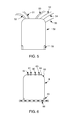
- FIG. 3 is a bottom view of an example of a light housing and smart device retrofitting unit, similar to FIG. 2 , with an additional external fan, according to the embodiments as disclosed herein;
- FIG. 4 is a bottom view of an example of a light housing and smart device retrofitting unit, similar to FIG. 2 , with an additional bladeless external fan, according to the embodiments as disclosed herein;
- FIG. 5 is a side view of an example of a retrofitting integrated can with additional connections: air ducts, water pipes, gas pipes, chemical pipes, fiber optics, copper wires, according to the embodiments as disclosed herein;
- FIG. 6 is a side view of an example of a retrofitting smart device unit that plugs into the integrated can of FIG. 5 , according to the embodiments as disclosed herein;
- FIG. 7 is a side view of an example of a retrofitting smart device unit with a fan that plugs into the integrated can of FIG. 5 , according to the embodiments as disclosed herein;
- FIG. 8 is a side view of an example of a retrofitting smart device unit scanning and/or locating objects, and displaying images and/or videos on the wall, table, and floor according to the embodiments as disclosed herein;
- FIG. 9 is a bottom view and side views of an example of a retrofitting smart device unit replacing tube light bulbs, according to the embodiments as disclosed herein;
- FIG. 10 is a bottom view of an example of a retrofitting smart device unit replacing tube light bulbs or tube light fixture with a bladeless fan that can rotate and extend, according to the embodiments as disclosed herein;
- FIG. 11 is a side view of an example of a retrofitting smart device unit replacing tube light bulbs or tube light fixture with a bladeless fan that can rotate and extend, according to the embodiments as disclosed herein;
- FIG. 12 is a bottom view of an example of a retrofitting smart device kits using combination of wired and/or wireless networks such as Wi-Fi, Li-Fi, Bluetooth, ZigBee, UWB, Ethernet, and/or fiber optic to form a mesh network to communicate with each other, with other devices, and with the Internet, according to the embodiments as disclosed herein;
- wired and/or wireless networks such as Wi-Fi, Li-Fi, Bluetooth, ZigBee, UWB, Ethernet, and/or fiber optic to form a mesh network to communicate with each other, with other devices, and with the Internet, according to the embodiments as disclosed herein;
- FIG. 13 is a side view of an example of a retrofitting smart device kits using combination of wired and/or wireless networks such as Wi-Fi, Li-Fi, Bluetooth, ZigBee, UWB, Ethernet, and/or fiber optic to form a mesh network to communicate with each other, with other devices, and with the Internet, according to the embodiments as disclosed herein;
- wired and/or wireless networks such as Wi-Fi, Li-Fi, Bluetooth, ZigBee, UWB, Ethernet, and/or fiber optic to form a mesh network to communicate with each other, with other devices, and with the Internet, according to the embodiments as disclosed herein;
- FIG. 14 is a side view and bottom of an example of smart device retrofitting unit for a recessed light fixture with a removable electrical adapter, and separated sensors, computer, smart devices, communication module, camera, projector, external ports (USB, HDMI, electrical outlet, etc.), using existing baffle trim, light bulb, and spring connectors, according to the embodiments as disclosed herein;
- FIG. 15 is a side view and bottom of an example of smart device retrofitting unit for a recessed light fixture with an attached electrical adapter, sensors, computer, smart devices, communication module, camera, projector, external ports (USB, HDMI, electrical outlet, etc.), baffle trim and spring connectors, using existing light bulb according to the embodiments as disclosed herein;
- FIG. 16 is a side view of an example of smart device retrofitting unit for a flush mount light fixture with an attached sensors, computer, smart devices, communication module, camera, projector, external ports (USB, HDMI, electrical outlet, etc.) sitting between the outlet box and existing light fixture according to the embodiments as disclosed herein;
- FIG. 17 is a top-down view of an example of smart device retrofitting unit for a flush mount light fixture with an attached sensors, computer, smart devices, communication module, camera, projector, external ports (USB, HDMI, electrical outlet, etc.) sitting between the outlet box and existing light fixture according to the embodiments as disclosed herein;
- FIG. 18 is a bottom-up view of an example of smart device retrofitting unit for a flush mount light fixture with an attached sensors, computer, smart devices, communication module, camera, projector, external ports (USB, HDMI, electrical outlet, etc.) sitting between the outlet box and existing light fixture according to the embodiments as disclosed herein;
- FIG. 19 is a side view of an example of smart device retrofitting unit for a flush mount light fixture with an attached sensors, computer, smart devices, communication module, camera, projector, external ports (USB, HDMI, electrical outlet, etc.) inside the casing box for existing light fixture according to the embodiments as disclosed herein;
- FIG. 20 is a side view of an example of smart device retrofitting unit for a flush mount light fixture with an attached sensors, computer, smart devices, communication module, camera, projector, external ports (USB, HDMI, electrical outlet, etc.) inside the casing box for integrated attachment for light fixture according to the embodiments as disclosed herein.
- Embodiments according to the present invention include a retrofit kit ( 4 , 33 , 43 , 45 , 81 , 77 , 97 , 237 , 247 , 127 , 137 , 140 , 150 , 160 , 170 , 180 , 190 , 200 ) for connected interchangeable smart devices and sensors ( 7 , 17 , 28 , 92 , 237 , 247 , 15 , 16 , 22 , 23 , 24 , 29 , 95 , 96 , 99 , 82 , 144 , 154 , 164 , 174 , 194 , 204 , 141 , 142 , 151 , 152 , 172 , 192 , 202 ) that are installed and connected to a recessed light can ( 8 , 58 ).
- a retrofit kit 4 , 33 , 43 , 45 , 81 , 77 , 97 , 237 , 247 , 127
- the kit power source comes from the connection of the male Edison screw socket ( 1 , 147 , 157 ) to the female Edison screw socket fixture ( 10 , 145 , 155 ).
- the power source can also come from other connections, including but not limited to a compatible retrofitted pluggable kit ( 67 , 77 ) that plugs into retrofitted pluggable can 58 , or into a can that has an existing compatible plug.
- FIGS. 3, 4 show examples of a housing with a fan attached, including blades ( 35 ) and bladeless fans ( 42 , 44 ).
- the base of the fan may pivot and/or rotate.
- the fan's functionalities, including blades, spin directions, speed, and pivot, are controlled manually and/or by hardware and software.
- FIG. 1 shows examples of types of attachments for the kit to the can.
- the torsion springs 3 are pushed up into the fixtures brackets 2 and lift the device into place.
- the attached springs 11 , 148 , 158
- FIGS. 5, 6, 7 show examples of an integrated can and kit for exchangeable and pluggable kits ( 67 , 77 ), where inputs and outputs ( 50 , 51 , 52 , 53 , 54 , 55 , 60 , 61 , 62 , 63 , 64 , 65 ) are connected to the can.
- the locks ( 59 , 69 , 79 ) secure the fixture to the can. These are examples of methods for securing the kit to the can, but these are not the only methods.
- the computer and the I/O modules ( 7 , 17 , 28 , 92 , 237 , 247 , 15 , 16 , 22 , 23 , 24 , 29 , 95 , 96 , 99 , 82 , 144 , 154 , 164 , 174 , 194 , 204 , 141 , 142 , 151 , 152 , 172 , 192 , 202 ) can be inside the housing of the kit ( 4 , 33 , 43 , 45 , 81 , 97 , 237 , 247 , 127 , 137 , 140 , 150 , 160 , 170 , 180 , 190 , 200 ) or connected with external interfaces ( 6 , 26 , 66 , 76 , 91 , 143 , 153 , 163 , 173 , 193 , 203 ).
- the input units include but are not limited to microphone(s), camera(s), a security camera(s), infrared camera(s), OCR(s), temperature sensor(s), chemical sensor(s), light sensor(s), a moisture sensor, a touch sensor, a motion sensor, a smoke detector, a carbon monoxide detector, a radar, a LIDAR, a radio waves receiver, an RFID reader, battery, wireless charger, and/or a GPS receiver.
- the output units include but are not limited to video projector(s), 2D/3D hologram projector(s), speaker(s), fan(s), light(s), laser(s), a heater, an air filter, an air conditioner, a humidifier, a dehumidifier, mist dispenser, chemical dispenser, a wireless charging station, and/or a docking station for drones and/or robots ( 15 , 16 , 22 , 23 , 24 , 29 , 95 , 96 , 99 , 82 , 144 , 154 , 164 , 174 , 194 , 204 ). Similar to the fan's functionalities, the modules are controlled by hardware and software.
- Cable adapters connect the unit to an existing electrical adapter and/or electrical outlets such as an Edison socket, three-prong electrical outlet, and other types of connectors.
- these devices are interconnected and managed by users and/or software agents running on the cloud and/or on mobile devices and/or the devices themselves to deliver customized and/or adaptable user experience based on individuals, groups, and/or objects.
- An assembly fitting inside a recessed, tube and track light can, or a canister that is mounted in/on the ceiling or wall can be retrofitted as a hub for multiple modular, interchangeable smart devices and sensors, controlled by hardware and software that are connected with each other, with other devices, and/or to the Internet.
- the communication interface between the modules and the main unit is USB or other standard wired or wireless interface and/or protocols.
- the input and output interfaces of the smart devices and sensors are controlled by software running on computer(s) in a kit and/or over a network in concert to support and/or direct people, devices, robots, and drones in carrying out their activities and tasks.
- the software can run digital assistant, music players, video games, video streaming, instructional videos, video/audio conferencing, telepresence, virtual reality, augmented reality, map, direction guidance, object locator and monitoring, people locator and monitoring, building monitoring, event monitoring, intercom, thermostat, humidity monitor, air filter, humidifier, cooling, heating, cloud services, and other applications.
- the computer and/or the smart devices and sensors have one or more of the following but are not limited to: lights, Wi-Fi adapter, Wi-Fi access point, Wi-Fi repeater, microphone, camera, a security camera, infrared camera, temperature sensor, chemical sensor, loudness sensor, light sensor, moisture sensor, motion sensor, photoelectric motion detector, photoelectric light sensor, smoke detector, carbon monoxide detector, radar, LIDAR (Light Detection And Ranging), radio wave receiver and/or sender, RFID reader, GPS receiver, video projector, 2D/3D hologram projector, speaker, fan, bladeless fan, laser, heater, air conditioner, humidifier, dehumidifier, chemical dispenser, docking station for a drone, docking station for a robot, battery, wireless charger, and the like.
- lights Wi-Fi adapter, Wi-Fi access point, Wi-Fi repeater, microphone, camera, a security camera, infrared camera, temperature sensor, chemical sensor, loudness sensor, light sensor, moisture sensor, motion sensor, photoelectric motion detector, photo
- the input interface can be a combination of voice, visual, motion, gesture, temperature, humidity, chemical, radar signal, laser, and other inputs.
- the output can be a combination of light, laser, image, video, 3D hologram, sound, warm air, cool air, water vapor, chemical, and electronic alarm or event.
- the integrated cans can have additional connections to other fixtures in the building such as, but not limited to, air ducts, water pipes, gas pipes, chemical pipes, fiber optics, and copper wires.
- This invention further enables the use of the smart device as a stand-alone appliance within a room of the building, or as a group of interconnected and/or complementary smart devices installed at various locations within the building managed by a central console accessible via the web or mobile application.
Landscapes
- Engineering & Computer Science (AREA)
- Computer Networks & Wireless Communication (AREA)
- General Engineering & Computer Science (AREA)
- Physics & Mathematics (AREA)
- General Physics & Mathematics (AREA)
- Automation & Control Theory (AREA)
- Arrangement Of Elements, Cooling, Sealing, Or The Like Of Lighting Devices (AREA)
Abstract
The present invention relates to an assembly kit that fits inside are recessed light fixture, flush mount light fixture, tube light fixture, track light fixture or light tube that is mounted in/on the ceiling or wall for retrofitting various combinations of smart devices and sensors, as part of ambient intelligence.
Description
Embodiments of the disclosure relate to a smart devices kit for recessed light fixture(s) or tube light bulb(s) or tube light fixture or track light(s) or track light fixture or flush mount light fixtures.
Recessed, tube, flush mount, and track light fixtures, installed in ceilings and walls are in common use in residential and commercial buildings to provide a light source. Many smart devices and sensors need an electrical energy source and also need to be installed at fixed locations such as walls or ceilings. Housing for recessed, flush mount, tube or track light fixtures is the ideal enclosure to provide locations and energy source for smart devices and sensors.
Patent CN 2919296 Y discloses a hidden light source for portable electronic devices. Further, U.S. Pat. No. 6,948,831 B1 discloses an integrated assembly of motion-sensing electronics, optics and an electrical lamp fixture that is adapted for installation in a recess or a cavity in ceilings or on walls. Furthermore, Patent US 20070064433 A1 discloses to a recessed light assembly has an integrated loudspeaker.
In light of the above discussion, there seems to be a need for retrofitting current buildings to accommodate smart devices and sensors where locations and electricity are required. Housings such as those for recessed, tube, flush mount, and track light fixtures provide both electrical power and locations for smart devices and sensors. The dimension of the fixtures is also an ideal fit for the packaging the devices. Recessed light and flush mount light housings are the ideal enclosure to provide locations and energy source for smart devices and sensors.
The principal object of the embodiments herein is to provide housing for connected smart devices and sensors fitting inside wall or ceiling mounted recessed, flushed, tube, and track light fixtures, including but are not limited to, cans or other forms of housing.
Another object of the embodiments herein is to provide housing for electronic circuitry or module that serves as a hub, access point, range extender for digital communication based on standards, including but not limited to, Wi-Fi or Bluetooth.
Yet another object of the embodiments herein is to provide alternate embodiments of the recessed, flush mount, tube and track light cans integrated with a smart device housing to enable pluggable units.
An additional object of the embodiments herein is to use the smart devices as a stand alone appliance within a room of the building, or as a group of interconnected and/or complementary smart devices installed at various locations within the building managed by software.
The present invention relates to a kit assembly for an interchangeably connected the computer and/or smart devices to be installed in a recessed, flush mount, tube or track light fixture. The kit assembly includes a socket connector including a wire with a male Edison socket (or a different type of socket appropriate for the light fixture being retrofitted) at one end and a universal electrical connector at the other end. Further, the kit assembly includes a retrofitting kit comprising of a socket connector, torsion springs and/or spring connector and/or other connector(s), and a smart devices and sensor unit. Furthermore, the kit assembly includes software that controls at least one of a pivot and rotation of the base of the kit to direct the inputs and outputs of the smart devices and sensors. Moreover, the kits assembly includes multiple smart devices within a building or any logical boundary that can be managed and provisioned by software.
These and other aspects of the embodiments herein will be better appreciated and understood when considered in conjunction with the following description and the accompanying drawings. It should be understood, however, that the following descriptions, while indicating preferred embodiments and numerous specific details thereof, are given by way of illustration and not of limitation. Many changes and modifications may be made within the scope of the embodiments herein without departing from the spirit thereof, and the embodiments herein include all such modifications.
In the accompanying figures, similar reference numerals may refer to identical or functionally similar elements. These reference numerals are used in the detailed description to illustrate various embodiments and to explain various aspects and advantages of the present disclosure.
The above-mentioned needs are met by a smart device kit for recessed light housing or flush mount light housing or tube light bulb(s) or tube light fixture or track light(s) or track light fixture. The following detailed description is intended to provide example implementations to one of ordinary skill in the art and is not intended to limit the invention to the explicit disclosure, as one ordinary skill in the art will understand that variations can be substituted that are within the scope of the invention as described.
These and other features of the present invention will become readily apparent upon further review of the following specification and drawings. Other goals and advantages of the invention will be further appreciated and understood when considered in conjunction with the following description and accompanying drawings. While the following description may contain specific details describing particular embodiments of the invention, this should not be construed as limitations to the scope of the invention, but rather as an exemplification of preferable embodiments. For each aspect of the invention, many variations are responsible as suggested herein that are unknown to those of ordinary skill in the art. A variety of changes and modifications can be made within the scope of the invention without departing from the spirit thereof.
The following detailed description is intended to provide example implementations to one of ordinary skill in the art and is not intended to limit the invention other explicit disclosure. As one of ordinary skill in the art will understand, variations can be substituted that are within the scope of the invention as described.
-
- Edison socket, male adapter: 1, 147, 157
- Edison socket, female adapter: 10, 145, 155
- Brackets: 2
- Wire hooks and/or springs:3, 148, 158
- Device housings or device fixture: 4, 33, 43, 45, 81, 97, 237, 247, 127, 137, 140, 150, 160, 170, 180, 190, 200
- Attachment hole: 5
- Attachment spring and hook: 11, 148, 158
- Electrical connectors, male and female: 14, 19
- Interchangeable smart devices, sensors, computer, wire-free charging transmitter, and/or battery: 7, 17, 28, 92, 141, 142, 151, 152, 172, 192, 202
- Recessed light can: 8, 80
- Cover plate: 9
- External interface and/or port (USB, HDMLI, electrical outlet, etc): 6, 26, 66, 76, 91, 143, 153, 163, 173, 193, 203
- USB, HDMI, electrical, etc. cables: 25, 83, 84,
- Spring/Hook connector ring: 12, 13
- Microphones, speakers, cameras, or projectors: 15, 16, 22, 23, 24, 29, 95, 96, 99, 82, 144, 154, 164, 174, 194, 204
- Speaker: 21, 31, 41
- LED lights: 20, 30, 40, 90
- Antennas for wireless modules: 27, 93
- Fans: 35, 75
- Bladeless fan: 42, 44, 232, 242
- Light tube housing, double light tube housing, or light tube fixture: 94
- Electrical connectors: 97, 98
- Wall: 85
- Table top, counter top, pool table, floor, flat surface, etc.: 86, 87
- Projected images and/or videos: 88, 89
- Retrofitted pluggable can: 58
- Retrofitted pluggable kit: 67, 77
- Enclosure locks: 59, 69, 79
- Vent, air filter, humidifier, fan: 243
- Fan connector: 244
- Wires (electrical, fiber optics, Ethernet): 53, 54, 55, 121
- Air ducts (inlet, outlet): 50, 51
- Water tube: 52
- Wire connectors (electrical, fiber optics, Ethernet): 63, 64, 65
- Air duct connectors (inlet, outlet): 60, 61
- Water tube connector: 62
- Tube light fixture retrofitted kit: 231, 241
- Radio waves or RF: 122, 132
- Light: 123, 133
- Computer or electronic device: 131
- Outlet box: 162
- Wire nut: 168, 198
- Keyhole slot: 165, 175, 195
- Mounting screw: 161, 181, 191
- Flush mount lighting fixture: 167, 197, 207
- Baffle trim: 149, 159
The terms “an” and “a” herein do not denote a limitation of quantity, but rather denote the presence of at least one of the referenced items.
Embodiments according to the present invention include a retrofit kit (4, 33, 43, 45, 81, 77, 97, 237, 247, 127, 137, 140, 150, 160, 170, 180, 190, 200) for connected interchangeable smart devices and sensors (7, 17, 28, 92, 237, 247, 15, 16, 22, 23, 24, 29, 95, 96, 99, 82, 144, 154, 164, 174, 194, 204, 141, 142, 151, 152, 172, 192, 202) that are installed and connected to a recessed light can (8,58). The kit power source comes from the connection of the male Edison screw socket (1, 147, 157) to the female Edison screw socket fixture (10, 145, 155). In another embodiment, the power source can also come from other connections, including but not limited to a compatible retrofitted pluggable kit (67, 77) that plugs into retrofitted pluggable can 58, or into a can that has an existing compatible plug.
The computer and the I/O modules (7, 17, 28, 92, 237, 247, 15, 16, 22, 23, 24, 29, 95, 96, 99, 82, 144, 154, 164, 174, 194, 204, 141, 142, 151, 152, 172, 192, 202) can be inside the housing of the kit (4, 33, 43, 45, 81, 97, 237, 247, 127, 137, 140, 150, 160, 170, 180, 190, 200) or connected with external interfaces (6, 26,66, 76, 91, 143, 153, 163, 173, 193, 203). The input units include but are not limited to microphone(s), camera(s), a security camera(s), infrared camera(s), OCR(s), temperature sensor(s), chemical sensor(s), light sensor(s), a moisture sensor, a touch sensor, a motion sensor, a smoke detector, a carbon monoxide detector, a radar, a LIDAR, a radio waves receiver, an RFID reader, battery, wireless charger, and/or a GPS receiver. The output units include but are not limited to video projector(s), 2D/3D hologram projector(s), speaker(s), fan(s), light(s), laser(s), a heater, an air filter, an air conditioner, a humidifier, a dehumidifier, mist dispenser, chemical dispenser, a wireless charging station, and/or a docking station for drones and/or robots (15, 16, 22, 23, 24, 29, 95, 96, 99, 82, 144, 154, 164, 174, 194, 204). Similar to the fan's functionalities, the modules are controlled by hardware and software.
It is a feature and aspect of the present invention to provide housing for connected smart devices and sensors fitting inside wall or ceiling mounted the recessed, flush mount, tube, and track light fixtures, including but not limited to, cans or other forms of housing. Cable adapters connect the unit to an existing electrical adapter and/or electrical outlets such as an Edison socket, three-prong electrical outlet, and other types of connectors. As part of the ambient intelligence, these devices are interconnected and managed by users and/or software agents running on the cloud and/or on mobile devices and/or the devices themselves to deliver customized and/or adaptable user experience based on individuals, groups, and/or objects.
An assembly fitting inside a recessed, tube and track light can, or a canister that is mounted in/on the ceiling or wall can be retrofitted as a hub for multiple modular, interchangeable smart devices and sensors, controlled by hardware and software that are connected with each other, with other devices, and/or to the Internet. The communication interface between the modules and the main unit is USB or other standard wired or wireless interface and/or protocols. The input and output interfaces of the smart devices and sensors are controlled by software running on computer(s) in a kit and/or over a network in concert to support and/or direct people, devices, robots, and drones in carrying out their activities and tasks. On a device or a group of synchronized devices, the software can run digital assistant, music players, video games, video streaming, instructional videos, video/audio conferencing, telepresence, virtual reality, augmented reality, map, direction guidance, object locator and monitoring, people locator and monitoring, building monitoring, event monitoring, intercom, thermostat, humidity monitor, air filter, humidifier, cooling, heating, cloud services, and other applications. The computer and/or the smart devices and sensors have one or more of the following but are not limited to: lights, Wi-Fi adapter, Wi-Fi access point, Wi-Fi repeater, microphone, camera, a security camera, infrared camera, temperature sensor, chemical sensor, loudness sensor, light sensor, moisture sensor, motion sensor, photoelectric motion detector, photoelectric light sensor, smoke detector, carbon monoxide detector, radar, LIDAR (Light Detection And Ranging), radio wave receiver and/or sender, RFID reader, GPS receiver, video projector, 2D/3D hologram projector, speaker, fan, bladeless fan, laser, heater, air conditioner, humidifier, dehumidifier, chemical dispenser, docking station for a drone, docking station for a robot, battery, wireless charger, and the like. The input interface can be a combination of voice, visual, motion, gesture, temperature, humidity, chemical, radar signal, laser, and other inputs. The output can be a combination of light, laser, image, video, 3D hologram, sound, warm air, cool air, water vapor, chemical, and electronic alarm or event.
It is still a further aspect of the invention to provide alternate embodiments of the recessed, flush mount, tube, and light track cans integrated with a smart device housing to enable pluggable units. In addition to an electrical connection, the integrated cans can have additional connections to other fixtures in the building such as, but not limited to, air ducts, water pipes, gas pipes, chemical pipes, fiber optics, and copper wires.
This invention further enables the use of the smart device as a stand-alone appliance within a room of the building, or as a group of interconnected and/or complementary smart devices installed at various locations within the building managed by a central console accessible via the web or mobile application.
Through an illustrative embodiment of the invention has been shown and described, it is to be understood that various modifications and substitutions may be made without departing from the novel spirit and scope of the present invention.
Accordingly, the disclosure of the present invention is intended to be illustrative, but not limiting, of the scope of the invention, which is set forth in the following claims.
Claims (15)
1. A kit assembly to interchangeably connect at least one of a computing device, a plurality of smart devices, and a plurality of sensors, and to be installed in a recessed light fixture, comprising:
a first socket connector including at least one electrical connector appropriate for the light fixture being retrofitted;
a retrofitting kit comprising a second socket connector, at least one spring connector, and a communication unit;
the plurality of smart devices, within a building or any logical boundary, managed and provisioned by a software; and
a bladeless fan assembly, comprising:
a motor mounted inside a housing;
a hollow airflow guiding frame and a flow guiding set affixed to the housing; and
an electronic control unit that controls the speed and direction of the fan, and the pivot and rotation of the housing.
2. The kit assembly of claim 1 , wherein the software controls at least one of a pivot and rotation of a base of the kit to direct an input and an output of the plurality of smart devices and the plurality of sensors.
3. The kit assembly of claim 1 , wherein a communication among the plurality of sensors, the computing device, and the plurality of smart devices is a combination of wired and/or wireless protocol such as Wi-Fi, Li-Fi, Bluetooth, ZigBee, UWB, USB, HDMI, Ethernet, and/or fiber optic.
4. The kit assembly of claim 1 , wherein the plurality of smart devices and the plurality of sensors are wired or wireless network access points and/or repeaters including but not limited to Wi-Fi access points, Wi-Fi repeaters, microcell repeater, or microcell access point.
5. The kit assembly of claim 1 , wherein the plurality of smart devices and the plurality of sensors are part of one or more mesh networks with other devices and/or computers.
6. The kit assembly of claim 5 , wherein the plurality of smart devices and the plurality of sensors are controlled by the software running on the computing device in the kit, other kit(s), and/or other devices remotely over the network.
7. The kit assembly of claim 1 , wherein the plurality of smart devices and the plurality of sensors and/or the computing device interact with a plurality of electronic devices, animals, and people through their respective input and output interfaces.
8. The kit assembly of claim 1 , wherein the software runs digital assistant, music players, video games, video streaming, instructional videos, video/audio conferencing, telepresence, virtual reality, augmented reality, map, direction guidance, object locator and monitoring, people locator and monitoring, building monitoring, event monitoring, intercom, thermostat, humidity monitor, air filter, humidifier, cooling, heating, cloud services, and other applications.
9. The kit assembly of claim 1 , wherein the computing device, the plurality of smart devices and the plurality of sensors are one or more of a microphone, a camera, a security camera, an infrared camera, a temperature sensor, chemical sensors, a light sensor, a moisture sensor, a touch sensor, a motion sensor, a smoke detector, a carbon monoxide detector, a radar, a LIDAR, a radio waves receiver, an RFID reader, a GPS receiver, a video projector, a 2D/3D hologram projector, speakers, lights, a fan, a bladeless fan, lasers, a heater, an air conditioner, a humidifier, a dehumidifier, battery, wireless battery charger, and/or chemical dispensers, wherein projectors, cameras, sensors, and/or software the assembly are used to interact and monitor people, animals, robots, events and/or the environment.
10. The kit assembly of claim 1 , further comprising:
an input interface configured to receive a plurality of input signals such as voice, visual, motion, gesture, temperature, humidity, chemical, radar signal, and laser, and wherein the output is a combination of at least one of a light, a laser, an image, a video, a 3D hologram, a sound, a warm air, a cool air, a water vapor, a chemical, and an electronic alarm.
11. The kit assembly of claim 1 , further comprising an electrical light source of fixed or variable color temperature and intensity controlled by the computing device running programmable software or remotely across a wired or wireless network.
12. The kit assembly of claim 1 , further comprising:
a fan assembly, comprising:
a motor mounted inside a housing; and
a plurality of blades each affixed to the housing.
13. The kit assembly of claim 1 , further comprising:
a retrofitted can with connectors for additional input and output, comprising:
air ducts/pipes for cool air and warm air;
water pipe for water sprinkler, cool air mist;
data communication wires;
electrical wires; and
locks for securing the kit.
14. The kit assembly of claim 1 , wherein the retrofitting kit comprising of the light tube, light tube fixture, or flush mount fixture retrofit kit with smart devices, sensors, and/or fan(s).
15. The kit assembly of claim 1 , wherein a kit power source is obtained from a connection of a male Edison screw socket for the light fixture being retrofitted to a female Edison screw socket in the light fixture.
Priority Applications (2)
| Application Number | Priority Date | Filing Date | Title |
|---|---|---|---|
| US15/411,994 US10310464B1 (en) | 2016-06-01 | 2017-01-21 | Smart devices kit for recessed light housing |
| CN201710311701.0A CN107228346A (en) | 2017-01-21 | 2017-05-05 | Smart machine external member for recessed light fixture housing |
Applications Claiming Priority (2)
| Application Number | Priority Date | Filing Date | Title |
|---|---|---|---|
| US201662343986P | 2016-06-01 | 2016-06-01 | |
| US15/411,994 US10310464B1 (en) | 2016-06-01 | 2017-01-21 | Smart devices kit for recessed light housing |
Publications (1)
| Publication Number | Publication Date |
|---|---|
| US10310464B1 true US10310464B1 (en) | 2019-06-04 |
Family
ID=66673255
Family Applications (1)
| Application Number | Title | Priority Date | Filing Date |
|---|---|---|---|
| US15/411,994 Expired - Fee Related US10310464B1 (en) | 2016-06-01 | 2017-01-21 | Smart devices kit for recessed light housing |
Country Status (1)
| Country | Link |
|---|---|
| US (1) | US10310464B1 (en) |
Cited By (8)
| Publication number | Priority date | Publication date | Assignee | Title |
|---|---|---|---|---|
| US20210178594A1 (en) * | 2018-05-28 | 2021-06-17 | Hitachi, Ltd. | Robot, Action Detection Server, and Action Detection System |
| US20220066730A1 (en) * | 2018-12-24 | 2022-03-03 | Zuma Array Ltd. | Framework for Handling Sensor Data in a Smart Home System |
| US20220065440A1 (en) * | 2018-12-18 | 2022-03-03 | David Frederick Small | Safety detection device and system |
| US11495118B2 (en) * | 2017-06-27 | 2022-11-08 | Oneevent Technologies, Inc. | Augmented reality of a building |
| GB2609949A (en) | 2021-08-18 | 2023-02-22 | Rahman Sajidur | A Space Servicing Assembly |
| US20230156061A1 (en) * | 2021-03-01 | 2023-05-18 | Daniel Goddard | Augmented Reality Positioning and Matching System |
| US20240151350A1 (en) * | 2021-03-03 | 2024-05-09 | Duux Holding B.V. | Expandable assembly for a ceiling "quatro plafoni" |
| US12501225B2 (en) | 2022-01-02 | 2025-12-16 | Poltorak Technologies Llc | Bluetooth enabled intercom with hearing aid functionality |
Citations (10)
| Publication number | Priority date | Publication date | Assignee | Title |
|---|---|---|---|---|
| US6548967B1 (en) | 1997-08-26 | 2003-04-15 | Color Kinetics, Inc. | Universal lighting network methods and systems |
| US20070164681A1 (en) | 2006-01-05 | 2007-07-19 | Canlyte Inc. | Sensing Light Fixture Device |
| US20110075422A1 (en) * | 2009-09-25 | 2011-03-31 | Cree Led Lighting Solutions, Inc. | Lighting devices comprising solid state light emitters |
| US8033686B2 (en) | 2006-03-28 | 2011-10-11 | Wireless Environment, Llc | Wireless lighting devices and applications |
| US20120112633A1 (en) | 2010-11-10 | 2012-05-10 | Jasopin Lee | System and Method For A Light Bulb Fixture with Sensor Switch and Its Operation and Method for operating the same |
| US8829799B2 (en) | 2006-03-28 | 2014-09-09 | Wireless Environment, Llc | Autonomous grid shifting lighting device |
| US20150130359A1 (en) * | 2013-11-14 | 2015-05-14 | LIFI Labs, Inc. | Resettable lighting system and method |
| US9049753B1 (en) | 2011-08-19 | 2015-06-02 | Appalachian Lighting Systems, Inc. | Lighting device monitor and communication apparatus |
| US20160073479A1 (en) * | 2013-05-01 | 2016-03-10 | BeON HOME INC. | Modular illumination device and associated systems and methods |
| US10047944B2 (en) * | 2014-01-10 | 2018-08-14 | Cordelia Lighting, Inc. | Recessed LED light fixture without secondary heat sink |
-
2017
- 2017-01-21 US US15/411,994 patent/US10310464B1/en not_active Expired - Fee Related
Patent Citations (10)
| Publication number | Priority date | Publication date | Assignee | Title |
|---|---|---|---|---|
| US6548967B1 (en) | 1997-08-26 | 2003-04-15 | Color Kinetics, Inc. | Universal lighting network methods and systems |
| US20070164681A1 (en) | 2006-01-05 | 2007-07-19 | Canlyte Inc. | Sensing Light Fixture Device |
| US8033686B2 (en) | 2006-03-28 | 2011-10-11 | Wireless Environment, Llc | Wireless lighting devices and applications |
| US8829799B2 (en) | 2006-03-28 | 2014-09-09 | Wireless Environment, Llc | Autonomous grid shifting lighting device |
| US20110075422A1 (en) * | 2009-09-25 | 2011-03-31 | Cree Led Lighting Solutions, Inc. | Lighting devices comprising solid state light emitters |
| US20120112633A1 (en) | 2010-11-10 | 2012-05-10 | Jasopin Lee | System and Method For A Light Bulb Fixture with Sensor Switch and Its Operation and Method for operating the same |
| US9049753B1 (en) | 2011-08-19 | 2015-06-02 | Appalachian Lighting Systems, Inc. | Lighting device monitor and communication apparatus |
| US20160073479A1 (en) * | 2013-05-01 | 2016-03-10 | BeON HOME INC. | Modular illumination device and associated systems and methods |
| US20150130359A1 (en) * | 2013-11-14 | 2015-05-14 | LIFI Labs, Inc. | Resettable lighting system and method |
| US10047944B2 (en) * | 2014-01-10 | 2018-08-14 | Cordelia Lighting, Inc. | Recessed LED light fixture without secondary heat sink |
Cited By (12)
| Publication number | Priority date | Publication date | Assignee | Title |
|---|---|---|---|---|
| US11495118B2 (en) * | 2017-06-27 | 2022-11-08 | Oneevent Technologies, Inc. | Augmented reality of a building |
| US20210178594A1 (en) * | 2018-05-28 | 2021-06-17 | Hitachi, Ltd. | Robot, Action Detection Server, and Action Detection System |
| US20220065440A1 (en) * | 2018-12-18 | 2022-03-03 | David Frederick Small | Safety detection device and system |
| US11898739B2 (en) * | 2018-12-18 | 2024-02-13 | Defining Future Solutions Pty Ltd | Safety detection device and system |
| US20220066730A1 (en) * | 2018-12-24 | 2022-03-03 | Zuma Array Ltd. | Framework for Handling Sensor Data in a Smart Home System |
| US12271652B2 (en) * | 2018-12-24 | 2025-04-08 | Zuma Array Ltd. | Framework for handling sensor data in a smart home system |
| US20230156061A1 (en) * | 2021-03-01 | 2023-05-18 | Daniel Goddard | Augmented Reality Positioning and Matching System |
| US11729234B2 (en) * | 2021-03-01 | 2023-08-15 | Daniel Goddard | Augmented reality positioning and matching system |
| US20240151350A1 (en) * | 2021-03-03 | 2024-05-09 | Duux Holding B.V. | Expandable assembly for a ceiling "quatro plafoni" |
| GB2609949A (en) | 2021-08-18 | 2023-02-22 | Rahman Sajidur | A Space Servicing Assembly |
| WO2023021164A1 (en) | 2021-08-18 | 2023-02-23 | Rahman Sajidur | A space servicing assembly |
| US12501225B2 (en) | 2022-01-02 | 2025-12-16 | Poltorak Technologies Llc | Bluetooth enabled intercom with hearing aid functionality |
Similar Documents
| Publication | Publication Date | Title |
|---|---|---|
| US10310464B1 (en) | Smart devices kit for recessed light housing | |
| US11460184B2 (en) | Modular smart quick connect device for electrical fixtures | |
| US20220408169A1 (en) | Outlet receptacle cover and mode throttling system | |
| US11025023B2 (en) | Smart quick connect device for electrical fixtures | |
| US20190323651A1 (en) | Stand Assembly for an Electronic Device Providing Multiple Degrees of Freedom and Built-in Cables | |
| US20200387176A1 (en) | System and method for providing and managing electricity | |
| US10290447B2 (en) | Wall-mounted smart switches and outlets for use in building wiring for load control, home automation, and/or security purposes | |
| US20160105021A1 (en) | Optical Wiring Systems and Methods | |
| US9414142B1 (en) | Wireless bath fan speaker | |
| US20140055611A1 (en) | Track-mount wireless camera fixture | |
| WO2016015500A1 (en) | Smart led lighting device and remote video chat system thereof | |
| WO2019183257A1 (en) | Modular wall unit system | |
| EP3565127A1 (en) | Integration device for integrating function modules | |
| US20260036295A1 (en) | Combination speaker and lighting fixture or other electrical element | |
| CN107228346A (en) | Smart machine external member for recessed light fixture housing | |
| JP4640286B2 (en) | Control system | |
| WO2006006576A1 (en) | Information processing device and information processing method | |
| JP2007166417A (en) | Remote monitor and control system | |
| JP2017073744A (en) | Information processing device and information processing system | |
| US20250062925A1 (en) | PoE Switch for Connecting External Devices | |
| US12281784B1 (en) | Device powered over coaxial cable via power adapter | |
| WO2017208262A1 (en) | System and method for wirelessly managing a plurality of functional units using a computing device | |
| JP2007313074A (en) | Digital pet system | |
| JP2007318383A (en) | Weather information display system | |
| CN205830125U (en) | A mobile lamp with gateway and routing functions |
Legal Events
| Date | Code | Title | Description |
|---|---|---|---|
| STCF | Information on status: patent grant |
Free format text: PATENTED CASE |
|
| FEPP | Fee payment procedure |
Free format text: MAINTENANCE FEE REMINDER MAILED (ORIGINAL EVENT CODE: REM.); ENTITY STATUS OF PATENT OWNER: SMALL ENTITY |
|
| LAPS | Lapse for failure to pay maintenance fees |
Free format text: PATENT EXPIRED FOR FAILURE TO PAY MAINTENANCE FEES (ORIGINAL EVENT CODE: EXP.); ENTITY STATUS OF PATENT OWNER: SMALL ENTITY |
|
| STCH | Information on status: patent discontinuation |
Free format text: PATENT EXPIRED DUE TO NONPAYMENT OF MAINTENANCE FEES UNDER 37 CFR 1.362 |
|
| FP | Lapsed due to failure to pay maintenance fee |
Effective date: 20230604 |