US10310458B2 - Process optimization by grouping mixed integer nonlinear programming constraints - Google Patents
Process optimization by grouping mixed integer nonlinear programming constraints Download PDFInfo
- Publication number
- US10310458B2 US10310458B2 US14/977,785 US201514977785A US10310458B2 US 10310458 B2 US10310458 B2 US 10310458B2 US 201514977785 A US201514977785 A US 201514977785A US 10310458 B2 US10310458 B2 US 10310458B2
- Authority
- US
- United States
- Prior art keywords
- group
- minlp
- model
- parameter
- switchable unit
- Prior art date
- Legal status (The legal status is an assumption and is not a legal conclusion. Google has not performed a legal analysis and makes no representation as to the accuracy of the status listed.)
- Active, expires
Links
Images


Classifications
-
- G—PHYSICS
- G05—CONTROLLING; REGULATING
- G05B—CONTROL OR REGULATING SYSTEMS IN GENERAL; FUNCTIONAL ELEMENTS OF SUCH SYSTEMS; MONITORING OR TESTING ARRANGEMENTS FOR SUCH SYSTEMS OR ELEMENTS
- G05B13/00—Adaptive control systems, i.e. systems automatically adjusting themselves to have a performance which is optimum according to some preassigned criterion
- G05B13/02—Adaptive control systems, i.e. systems automatically adjusting themselves to have a performance which is optimum according to some preassigned criterion electric
- G05B13/04—Adaptive control systems, i.e. systems automatically adjusting themselves to have a performance which is optimum according to some preassigned criterion electric involving the use of models or simulators
- G05B13/041—Adaptive control systems, i.e. systems automatically adjusting themselves to have a performance which is optimum according to some preassigned criterion electric involving the use of models or simulators in which a variable is automatically adjusted to optimise the performance
-
- G—PHYSICS
- G06—COMPUTING OR CALCULATING; COUNTING
- G06F—ELECTRIC DIGITAL DATA PROCESSING
- G06F17/00—Digital computing or data processing equipment or methods, specially adapted for specific functions
- G06F17/10—Complex mathematical operations
- G06F17/11—Complex mathematical operations for solving equations, e.g. nonlinear equations, general mathematical optimization problems
-
- F23N2023/40—
-
- F23N2023/44—
-
- F—MECHANICAL ENGINEERING; LIGHTING; HEATING; WEAPONS; BLASTING
- F23—COMBUSTION APPARATUS; COMBUSTION PROCESSES
- F23N—REGULATING OR CONTROLLING COMBUSTION
- F23N2223/00—Signal processing; Details thereof
- F23N2223/40—Simulation
-
- F—MECHANICAL ENGINEERING; LIGHTING; HEATING; WEAPONS; BLASTING
- F23—COMBUSTION APPARATUS; COMBUSTION PROCESSES
- F23N—REGULATING OR CONTROLLING COMBUSTION
- F23N2223/00—Signal processing; Details thereof
- F23N2223/44—Optimum control
-
- H02J2003/007—
-
- H—ELECTRICITY
- H02—GENERATION; CONVERSION OR DISTRIBUTION OF ELECTRIC POWER
- H02J—CIRCUIT ARRANGEMENTS OR SYSTEMS FOR SUPPLYING OR DISTRIBUTING ELECTRIC POWER; SYSTEMS FOR STORING ELECTRIC ENERGY
- H02J2203/00—Indexing scheme relating to details of circuit arrangements for AC mains or AC distribution networks
- H02J2203/20—Simulating, e g planning, reliability check, modelling or computer assisted design [CAD]
Definitions
- MINLP Mixed Integer Nonlinear Programming
- SimSci ROMeo available from Schneider Electric, is a Rigorous On-line Modeling and Equation-based Optimization (ROMEO) module for continuous process optimization.
- ROMEO Rigorous On-line Modeling and Equation-based Optimization
- aspects of the present invention improve the fields of process control and automation and process simulation by employing online first-principles simulation techniques in conjunction with a Mixed Integer Nonlinear Programming (MINLP) solver in real-time.
- MINLP Mixed Integer Nonlinear Programming
- Grouping of units that comprise a process model as a mechanism to implement constraints for MINLP utility optimization provide optimization of nonlinear continuous processes that incorporate switchable units.
- this approach allows the determination of an optimal operating state while taking into account changing process parameters without requiring case studies that model switchable units to be taken offline.
- aspects of the present invention also provide improvements in computer technology, namely, process model simulation and optimization.
- a system in an aspect, includes a sensor and a control system.
- the sensor generates data representing a current state of each of a plurality of process units within a continuous process.
- the control system receives the generated data and generates an operating state of the continuous process.
- the control system includes a processor that executes computer-executable components.
- One of the computer-executable components includes a plurality of model components that implement a first-principle equation.
- the first-principle equation represents at least one of the process units and two or more of the model components comprise a group.
- Another of the computer-executable components includes a plurality of switch components that each comprises a corresponding one of the plurality of model components.
- the switch components each implement an MINLP behavior of the corresponding model component.
- Each of the switch components also includes a group identifier parameter of the group and a group complement parameter that encodes an operational constraint of the continuous process.
- Another of the computer-executable components includes an MINLP solver component that switches each of the model components of the group between an active state and an inactive state based in part on the group identifier parameter and the group complement parameter during a simulation of an operation of the plurality of model components.
- the MINLP solver component performs the switching during the simulation to generate the operating state of the continuous process in real-time with an operation of the continuous process.
- a computer-implemented method for generating an optimal operating state of a continuous process includes receiving, by a control system, data from a sensor within the continuous process.
- the data represents a current state of each of a plurality of process units within the continuous process.
- the method also includes simulating, by the control system, an operation of a plurality of unit models in conjunction with an MINLP solver in real-time.
- the unit models each represent one of the process units via a first-principle equation.
- the method further includes grouping, by the control system, two or more of the unit models into a group based on an operating constraint of the continuous process.
- Each of the unit models of the group have an MINLP switch that implements MINLP behavior of the unit model and encodes the operating constraint.
- the method continues with the control system switching the MINLP switch of each unit model of the group between an active state and an inactive state during the simulation based in part on the operating constraint.
- the control system also generates an operating state of the continuous process that satisfies the operating constraint based on the simulating, grouping, and switching.
- a computer-readable storage device has computer-executable modules stored thereon for generating an operating state of a continuous process.
- the modules include a plurality of model modules, a plurality of MINLP switch modules, and a solver module.
- the model modules each define a plurality of unit models that represent a process unit within the continuous process via a first-principle equation during an execution of the model module by a processor.
- Two or more of the model modules comprise a group.
- the MINLP switch modules each transition a corresponding model module of the group between an active state and an inactive state based on a parameter that encodes an operating constraint of the continuous process during an execution of the MINLP switch module by the processor.
- the MINLP switch modules each implement an MINLP behavior of the corresponding model module.
- the solver module simulates an operation of the model modules and the MINLP switch modules in real-time during an execution of the solver module by the processor.
- the solver module generates the operating state of the continuous process where the operating state satisfies the parameter encoding the operating constraint of the continuous process.
- FIG. 1 is a block diagram of an exemplary ROMEO solver system embodying aspects of the invention.
- FIG. 2 is a block diagram on an exemplary MINLP switch embodying aspects of the invention.
- FIGS. 3A and 3B are diagrams illustrating an exemplary graphical user interface of MINLP switch configuration parameters.
- FIG. 4 is a block diagram illustrating an exemplary grouping of MINLP units across sub-flowsheet boundaries.
- FIGS. 5 and 6 are block diagrams of exemplary continuous processes embodying aspects of the invention.
- FIGS. 7-10 are flow charts illustrating exemplary workflow processes of grouping MINLP units embodying aspects of the invention.
- FIG. 1 is a block diagram of a ROMEO solver system embodying aspects of the invention, including implementing Mixed Integer Nonlinear Programming (MINLP) behavior.
- MINLP Mixed Integer Nonlinear Programming
- computer-executable instructions are executed to solve a process problem by an MINLP switch in conjunction with constraints of a model that can simulate the behavior of desired process units.
- the illustrated system includes a unit model module 102 , a model-variable module 104 , a constraint module 106 , an MINLP switch 108 , MINLP parameters 110 , an MINLP interface 112 , constraint input data 114 , a constraint interface 116 , a process 118 , process input data 120 , a process definition interface 122 , a solver module 124 , an optimal operating state 126 , and a sensor 128 .
- FIG. 1 illustrates an MINLP modeling system and method.
- non-invasive MINLP modeling systems and methods as described in U.S. patent application Ser. No. 14/745,961, filed Jun. 6, 2015, and hereby incorporated by reference in its entirety, may also be utilized with aspects of the present invention.
- Systems and methods described herein solve nonlinear process problems while optimizing for certain considerations (e.g., operating penalty, cost, etc.) while ensuring the process meets plant constraints. Aspects of the present invention are described herein with respect to optimizing energy source usage in a continuous process but it is to be understood by one skilled in the art that the systems and methods described herein are also capable of optimizing continuous processes with respect to considerations other than energy source usage.
- Energy source (e.g., utility) optimization in continuous processes involves calculating the best solution to meet the energy demand, while operating the underlying process optimally with desired operational specifications and keeping the operational expenses as low as possible.
- the utility optimization problem is relevant when there are multiple energy sources that can supply the desired quantum of energy. For example, there may be some sources of energy endemic to the process and other sources of energy that are extraneous to the process.
- Utility optimization requires the capability to switch among available energy sources depending on the economics, energy and material balance, and underlying nonlinear process optimality.
- These computational issues require an MINLP solver in conjunction with models that can simulate the switching behavior of process units. While modeling the process for MINLP, it is advantageous to encode operational constraints of the process or plant into the model. Such constraints simplify the task for the MINLP solver by focusing the search for a solution in only the feasible regions.
- Grouping of units that comprise a process model as a mechanism to implement constraints for MINLP utility optimization is the subject of aspects of the present invention.
- variables in vector z are free-independent and z is the vector of integer switches in the problem.
- variables in vector z vary between [0, 1] and is of dimension B ⁇ 1.
- a Rigorous Online Modeling and Equation-based Optimization (ROMEO) modeling system allows a user to construct a flowsheet of the process with models or units from a pre-built library or from models built by the user.
- the unit model module 102 (i.e., unit) comprises a storage memory device having stored thereon processor-executable instructions for defining a first-principle model of a unit comprising a continuous process that has been modified to implement MINLP behavior.
- unit 102 defines a first-principle model of a motor in the process 118 and includes the model-variable module 104 , the constraint module 106 , and the MINLP switch 108 .
- Additional units include, but are not limited to, generators, steam turbines, boiler fuel flows, motors, shafts, and the like. Additional details of unit 102 are further described herein and in U.S. patent application Ser. No. 14/745,961 incorporated by reference above.
- model-variable module 104 comprises, in an embodiment, a storage memory device having stored thereon process-executable instructions for defining a model-variable of the first-principle model of unit 102 .
- model-variable module 104 defines the shaft power of a motor as the model-variable of interest.
- Other model-variables include, but are not limited to, the shaft power of a generator, the actual work of a steam turbine, and flow rate of boiler fuel flows. Additional details of model-variable module 104 are further described herein and in U.S. patent application Ser. No. 14/745,961 incorporated by reference above.
- the constraint module 106 comprises a storage memory device having stored thereon processor-executable instructions for defining one or more constraints of the first-principle model of unit 102 .
- constraint module 106 defines a minimum value (e.g., 0) and a maximum value (e.g., 100) of the shaft power of a motor.
- operation of a continuous process involves several constraints based on factors such as capacity, safety, economics, and the like. For example, due to bus-bar current loading limits, there might be a constraint that either one of two motors connected to the same bus-bars can operate at a time. Similarly, constraints may exist regarding switching in either a motor or a steam turbine to meet a given load, but not both simultaneously. Additionally, there may be constraints that specify a group of units should operate simultaneously if required by the load demands and the units by themselves cannot meet the demand. In an exemplary general case, there may be a need to encode more complex operational constraints.
- aspects of the present invention as further described herein provide solutions to these situations by specifying and encoding operational constraints (e.g., of a plant) through grouping of model units.
- grouping is a specification of a set of units that should be constrained to behave in a certain manner, as further described herein.
- the MINLP switch 108 of FIG. 1 comprises a storage memory device having stored thereon processor-executable instructions for implementing MINLP behavior in the first-principle model of unit 102 , in an exemplary embodiment.
- MINLP switch 108 may implement MINLP behavior in a motor model defined by unit 102 by modifying the shaft power of the motor.
- a unit 102 including MINLP switch 108 is referred to as an MINLP unit 102 . Additional details of MINLP switch 108 are further described herein and in U.S. patent application Ser. No. 14/745,961 incorporated by reference above.
- MINLP switch 108 may be referred to as a switch component in some embodiments.
- the MINLP interface 112 receives MINLP parameters 110 from a source such as a user, another software program, or a device, for example.
- the MINLP interface 112 provides received MINLP parameters 110 to MINLP switch 108 .
- the MINLP switch 108 uses the received MINLP parameters 110 to customize the MINLP behavior of the first-principle model of unit 102 .
- MINLP interface 112 is a graphical user interface (GUI) that allows a user to set a threshold for switching based upon parameters including a startup cost, a shutdown cost, and time period, as further described herein. Further details regarding MINLP interface 112 are described herein.
- GUI graphical user interface
- the constraint interface 116 of FIG. 1 receives constraint input data 114 from a source such as a user, another software program, or a device, for example.
- the constraint interface 116 provides the received constraint input data 114 to constraint module 106 .
- the constraint module 106 uses the received constraint input data 114 to define the constraints of the first-principle model of unit 102 .
- constraint interface 116 is a GUI that allows a user to set constraints such as a minimum and maximum shaft power, for example, of a motor which unit 102 defines.
- the constraint interface 116 and MINLP interface 112 may be combined into a single interface in accordance with aspects of the invention. Further details regarding constraint interface 116 are described herein.
- process 118 is a continuous process, such as a refinery, chemical, or petrochemical plant operation, for example, and/or its control system.
- process 118 includes at least one sensor 128 .
- Other aspects of process 118 are further defined herein.
- the process definition interface 122 receives process input data 120 from a source such as a user, another software program, or a device (e.g., a sensor and/or a unit in process 118 ), for example.
- the process input data 120 represents a current state of process 118 and corresponds to the process problem to be solved.
- the process definition interface 122 provides the received process input data 120 to the solver module 124 for use in executing an interactive model to solve the process problem as described herein.
- process definition interface 122 is part of a ROMEO modeling system that allows a user to construct a flowsheet of process 118 with models or units from a pre-built library or from models built by the user.
- the solver module 124 comprises a storage memory device having stored thereon processor-executable instructions for defining an iterative process having variables.
- the variables have certain values which, when applied to the iterative process, converge the iterative process to a solution.
- the variables have other values, which, when applied to the iterative process, do not converge the iterative process to a solution.
- solver module 124 comprises a ROMEO module.
- solver module 124 is an MINLP solver module.
- the solver module 124 is adapted for changing the value of a binary MINLP variable in order to switch unit 102 on and off in the simulation while converging to an optimal solution (e.g., optimal operating state 126 ) for the underlying nonlinear process 118 .
- an optimal solution e.g., optimal operating state 126
- Commonly assigned U.S. patent application Ser. No. 13/968,119 which describes a nonlinear correction factor module for use with, for example, a ROMEO solver, is incorporated by reference in its entirety. Additional details regarding solver module 124 are further described in U.S. patent application Ser. No. 14/745,961 incorporated by reference above.
- At least unit model module 102 and solver module 124 comprise a control system adapted for transmitting control information to components (e.g., actuators) within process 118 and receiving sensory and feedback data from components (e.g., sensors) within process 118 .
- the control system and process 118 may communicate via a telecommunications network that facilitates the exchange of data, such as those that operate according to the IEEE 802.3 (e.g., Ethernet) and/or the IEEE 802.11 (e.g., Wi-Fi) protocols, for example.
- the control system and process 118 communicate via any medium that allows data to be physically transferred through serial or parallel communication channels (e.g., copper wire, optical fiber, computer bus, wireless communication channel, etc.).
- the control system is one of a distributed control system (DCS) and a centralized database run in an online mode.
- DCS distributed control system
- FIG. 2 illustrates an exemplary embodiment of MINLP switch 108 that uses grouping as a mechanism to implement constraints for MINLP optimization.
- MINLP switch 108 includes a group identifier parameter 110 -A, a group complement parameter 110 -B, and a friend parameter 110 -C.
- the group identifier parameter 110 -A identifies a group of MINLP units to which MINLP unit 102 including belongs.
- the group identifier 110 -A may be edited via MINLP GUI 112 such that all MINLP units 102 with the same group identifier 110 -A are members of the same group. In other words, if two MINLP units 102 are in a group, then they will share the same group identifier 110 -A.
- group identifier 110 -A is a string of alphanumeric characters.
- the group complement 110 -B indicates whether MINLP unit 102 switches in the same manner as other MINLP units with the same group identifier 110 -A or complementary to other MINLP units with the same group identifier 110 -A.
- group complement parameter 110 -B is a binary option, and can be marked by such indicators as “yes”, or “active”, or a checked checkbox on MINLP GUI 112 .
- the group complement parameter 110 -B may also be unmarked by such indicators as “no”, “inactive”, or an unchecked checkbox on MINLP GUI 112 .
- MINLP unit 102 For example, if group complement 110 -B is marked, then the corresponding MINLP unit 102 will be switched on when other MINLP units of the group having their corresponding group complements unmarked are switched off. Likewise, if group complement 110 -B is marked, then the corresponding MINLP unit 102 will be switched off when other MINLP units of the group having their group complements unmarked are switched on. In this manner, an MINLP unit 102 having its group complement 110 -B marked will exhibit complementary behavior when compared to other MINLP units having the same group identifier 110 -A and unmarked group complements.
- the friend parameter 110 -C provides an association with non-MINLP units 102 that should behave in an identical manner as MINLP unit 102 , as further described herein.
- various rules govern group behavior and the rules may be implemented singly, all together, or as a mix of various ones.
- One rule is that MINLP units 102 marked as belonging to the same group share a fundamental switching law.
- Another rule is that all MINLP units 102 in a group (e.g., having the same group identifier 110 -A) switch on or off simultaneously, unless they are marked as complements (e.g., via group complement parameter 110 -B).
- Yet another rule is that MINLP units 102 in a group marked as complement switch in opposition to the rest of the group. In other words, if the group members turn on, then the complement unit turns off, and vice-versa.
- each MINLP-aware unit 102 declares the group to which it belongs (e.g., via group identifier 110 -A).
- Each MINLP-aware unit when instantiated, also has a default group identifier 110 -A that is unique to that unit.
- a group cannot have a membership of zero, which is impossible by definition.
- a group can have membership across sub-flowsheet boundaries. By definition, a unit can belong to only one group (i.e., a unit cannot belong to more than one group at the same time).
- Group names as further described herein, follow the naming convention of the associated ROMEO solver system.
- FIGS. 3A and 3B illustrate exemplary MINLP graphical user interfaces (GUI) 112 and constraint GUIs 116 .
- GUI MINLP graphical user interfaces
- FIGS. 3A and 3B illustrate exemplary MINLP graphical user interfaces (GUI) 112 and constraint GUIs 116 .
- GUI graphical user interfaces
- FIGS. 3A and 3B illustrate exemplary MINLP graphical user interfaces (GUI) 112 and constraint GUIs 116 .
- GUI MINLP graphical user interfaces
- FIGS. 3A and 3B illustrate exemplary MINLP graphical user interfaces (GUI) 112 and constraint GUIs 116 .
- a configuration window incorporating aspects of MINLP GUI 112 and constraint GUI 116 is illustrated.
- the configuration window appears on a display device via invocation of a “MINLP Manager” feature associated with MINLP switch 108 .
- the configuration window includes entries (e.g., 102 -A, 102 -B,
- each MINLP unit 102 has a default group identifier 110 -A that is unique to each MINLP unit 102 .
- MINLP unit 102 -A has group identifier 110 -A “Group1” while MINLP unit 102 -B has group identifier 110 -A “Group2,” MINLP unit 102 -C has group identifier 110 -A “Group7,” and MINLP unit 102 -D has group identifier 110 -A “Group8.”
- each of the MINLP units 102 illustrated in FIG. 3A have their group complement parameter 110 -B unmarked (e.g., checkbox unchecked).
- FIG. 3B illustrates customization of MINLP units 102 .
- MINLP unit 102 -A has group identifier 110 -A “MotorGroup” and has its group complement parameter 110 -B marked (e.g., checkbox checked).
- MINLP unit 102 -B has group identifier 110 -A “MotorGroup” and its group complement parameter 110 -B unmarked.
- MINLP units 102 -A and 102 -B are members of the same group (e.g., “MotorGroup”) and MINLP unit 102 -A switches complementarily with respect to the other units of the group (e.g., MINLP unit 102 -B).
- each of MINLP units 102 -C and 102 -D are members of the same group by virtue of their group identifiers 110 -A being identical (e.g., “STGroup”) and exhibit complementary behavior relative to the other units of the group by virtue of their group complement parameters 110 -B being marked.
- group identifiers 110 -A being identical (e.g., “STGroup”)
- group complement parameters 110 -B being marked.
- MINLP units 102 -C and 102 -D turn off, then the other units of group (e.g., “ST1” and “ST4”) turn on, and vice-versa.
- FIG. 4 illustrates an exemplary grouping of MINLP units 102 across sub-flow sheet boundaries.
- a ROMEO solver system embodying aspects of the invention allows for aggregation of a model comprised of MINLP units in sub-flowsheets.
- a main flowsheet 402 includes a sub-flowsheet 404 which further includes a sub-sub-flowsheet 406 .
- sub-flowsheets are solved in isolation of other sub-flowsheets.
- MINLP units 102 - 1 , 102 - 2 , 102 - 3 and 102 - 10 are members of main flowsheet 402 .
- MINLP units 102 - 4 , 102 - 5 , and 102 - 6 are members of sub-flowsheet 404 and MINLP units 102 - 7 , 102 - 8 , and 102 - 9 are members of sub-sub-flowsheet 406 .
- Aspects of the invention permit specification of the behavior of grouping of MINLP units 102 across sub-flowsheet boundaries. In the embodiment illustrated by FIG.
- MINLP units 102 - 1 and 102 - 2 comprise a group 408
- MINLP units 102 - 6 , 102 - 8 , 102 - 9 , and 102 - 10 comprise a group 410
- MINLP units 102 - 5 and 102 - 7 comprise a group 412
- MINLP units 102 - 3 and 102 - 4 comprise a group 414 .
- the group 410 straddles the boundaries between main flowsheet 402 and sub-flowsheet 404 as well as the boundary between sub-flowsheet 404 and sub-sub-flowsheet 406 .
- the group 412 straddles the boundary between sub-flowsheet 404 and sub-sub-flowsheet 406 .
- the group 414 straddles the boundary between main flowsheet 402 and sub-flowsheet 404 .
- the group 408 does not straddle a boundary because both of its comprising MINLP units 102 - 1 and 102 - 2 are members of main flowsheet 402 .
- all groups 408 , 410 , 412 , and 414 are active in the context of solving a model at the level of main flowsheet 402 because the comprising MINLP units of each group are members of main flowsheet 402 or its sub-flowsheets (i.e., sub-flowsheet 404 and sub-sub-flowsheet 406 ).
- sub-flowsheet 404 sub-flowsheets
- groups 410 and 412 are broken across the boundary between main flowsheet 402 and sub-flowsheet 404 . Accordingly, when the context for model solution is set to sub-flowsheet 404 , the group membership size of group 414 is only one unit (i.e., unit 102 - 4 ) because only unit 102 - 4 is visible in the context of sub-flowsheet 404 . Similarly, when the context for model solution is set to sub-flowsheet 404 , group 410 is broken and its membership is only three units (i.e., units 102 - 6 , 102 - 8 , 102 - 9 ).
- group 412 is visible with a membership of one unit (i.e., unit 102 - 7 ) and group 410 with a membership of two units (i.e., units 102 - 8 and 102 - 9 ).
- the grouping appropriately considers which groups to admit and which groups to ignore. For example, when sub-flowsheet 404 is solved in isolation then only units 102 - 4 , 102 - 5 , and 102 - 6 are in context.
- the grouping of groups 410 , 412 , and 414 is thus modified in size to consider only those units that are in context (e.g., each of groups 410 , 412 , 414 have a group size of one unit).
- the B MINLP units 102 which were binary variables, are now marked as dependent real variables.
- the MINLP solver e.g. solver module 124
- the worst-case complexity for branching of the MINLP solver is now 2 M+1 ⁇ 1 assuming binary variables. Accordingly, a reduction in the theoretical worst-case complexity is possible because M B, and the amount of reduction is dependent upon M.
- the MINLP solver e.g., solver module 124
- all MINLP units 102 appear in one group which results in a reduction from 2 B+1 ⁇ 1 NLP problems to only three NLP problems.
- FIG. 5 illustrates an exemplary process 118 including a steam source 502 , a turbine 504 , a motor 506 , a shaft 508 , and a driven process 510 .
- the turbine 504 and the motor 506 each correspond to an MINLP unit 102 and are in the same group (i.e., have the same group identifier 110 -A).
- turbine 504 is marked as a complement of motor 506 (i.e., when motor 506 is on turbine 504 is off, and vice-versa).
- a single binary grouping variable, x G implements the group relationship between turbine 504 and motor 506 . Accordingly, two constraining equations are required to relate turbine 504 and motor 506 in the group.
- Equation 2 represents motor 506 and Equation 3 represents turbine 504 :
- Equation 3 includes the complementary form of the grouping variable.
- x G is an independent variable and is computed by the ROMEO solving system (e.g., solver module 124 ).
- solver module 124 e.g., solver module 124
- the load on the MINLP solver (e.g., solver module 124 ) is reduced from solving two independent variables to solving just one independent variable.
- the model representing process 118 can be solved with x G that can represent the switching operations needed.
- Table 1 illustrates the status of the variables for the embodiment of FIG. 5 .
- FIG. 6 illustrates another exemplary process 118 including a steam source 602 , a first turbine 604 , a second turbine 606 , a motor 608 , a generator 610 , a driven process 612 , and shafts 614 .
- the first turbine 604 , the second turbine 606 , and the motor 608 each correspond to an MINLP unit 102 and are in the same group (i.e., each have the same group identifier 110 -A).
- motor 608 is marked as a complement of both first turbine 604 and second turbine 606 .
- the single binary grouping variable, x G implements the group relationship between first turbine 604 , second turbine 606 , and motor 608 .
- Equation 4 represents motor 608
- Equation 5 represents first turbine 604
- Equation 6 represents second turbine 606 :
- Equations 5 and 6 include the complementary form of the grouping variable x G .
- x G is an independent variable
- x Motor _ MINLPSwitch , x FirstTurbine _ MINLPSwitch , and x SecondTurbine _ MINLPSwitch lose their independent status to become dependent variables and are constrained to behave per the group switching. Accordingly, by using grouping, the load on the MINLP solver (e.g., solver module 124 ) is reduced from solving three independent variables to solving just one independent variable (e.g., x G ). Table 2 illustrates the status of the variables for the embodiment of FIG. 6 .
- FIG. 7 illustrates a sample workflow process in a ROMEO-based solver system.
- models are added to a flowsheet of a ROMEO-based modeling system. For example, a user may add models to the flowsheet via process definition interface 122 .
- MINLP switches 108 are attached to MINLP units 102 , thereby making the units 102 MINLP-active (e.g., MINLP units 102 ).
- a user may attach MINLP switches 108 to MINLP units 102 via process definition interface 122 and/or MINLP interface 112 .
- group identifier 110 -A and group complement parameter 110 -B are defined for each MINLP unit 102 .
- a user defines group identifiers 110 -A and group complement parameters 110 -B via MINLP interface 112 .
- aspects of the invention implement steps 708 through 714 via processor-executable instructions.
- solver module 124 implements steps 708 through 714 .
- a group leader is selected for each group. For example, out of all MINLP units 102 that have an identical group identifier 110 -A, one of the units is selected as the group leader, which is referred to as x G .
- group relationships are implemented via equations.
- a new equation is introduced for each MINLP switch 108 (e.g., x MINLPSwitch ), other than the group leader, for which no equation is required.
- group complement parameter 110 -B is marked
- Equation 7 is introduced.
- x MINLPSwitch ⁇ (1 ⁇ x G ) 0 (Equation 7)
- Equation 8 is introduced.
- x MINLPSwitch ⁇ x G 0 (Equation 8)
- Equations 7 and 8 are sent to the solver (e.g., solver module 124 ).
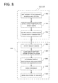
- FIG. 8 illustrates another sample workflow process in a ROMEO-based solver system.
- aspects of the invention introduce as many new group variables as there are groups, and as many new equations as there are MINLP units 102 , in order to encode the grouping constraints.
- An advantage of this approach is a clean separation of the model variables and the constraint equation variables, in addition to the theoretical reduction in worst-case branching complexity.
- aspects of the invention provide further advantages, including reducing the overall computing complexity, by not introducing new grouping variables but instead implicitly handling them.
- steps 702 , 704 , and 706 are performed as described above. After definition of the parameters at step 706 , aspects of the invention implement steps 802 through 810 via processor-executable instructions.
- solver module 124 implements steps 802 through 810 .
- a group leader is selected whose MINLP switch variable will be used as a group variable for all of the MINLP units 102 in the group.
- the group leader is referred to as x Group .
- each MINLP switch variable already knows the group to which it belongs as well as the group complement that it should present.
- each MINLP switch 108 is made aware of its group leader (e.g., the group leader selected at step 802 ).
- each MINLP unit 102 implements the group relationship via equations.
- Equation 9 if the current switch is not complementary with respect to the group leader (e.g. complement parameter 110 -B unmarked) or Equation 10 if the current switch is complementary with respect to the group leader (e.g. complement parameter 110 -B marked):
- the variables are marked.
- variable x MINLPSwitch is marked as a real dependent variable and the grouping variable x Group is marked as a free-independent binary variable.
- the equations are sent to the solver (e.g., solver module 124 ) at step 810 .
- solver e.g., solver module 124
- the embodiment illustrated by FIG. 8 has reduced the problem size from N+S+B+M variables to N+S+B variables, where N is the number of variables in the x vector, S is the number of variables in the y vector, B is the number of MINLP units 102 on the flowsheet, and M is the number groups (e.g., grouping variables), as further described herein.
- the number of constraining equations is reduced to N+B ⁇ M because the MINLP unit 102 that is the group leader does not introduce a new equation and there are M group leaders.
- the worst-case branching complexity is represented as 2 M+1 ⁇ 1, which makes it amenable to quicker overall solutions that require fewer computing resources than conventional solutions.
- FIG. 9 illustrates yet another sample workflow process in a ROMEO-based solver system.
- Equation 11 provides yet another implementation for grouping MINLP units.
- Equation 11 occurs in the MINLP switch unit of the group leader, which has access to all the members of its groups and their complements. Equation 11 is included in the MINLP switch unit of every group leader. This embodiment reduces the number of equations from N+B ⁇ M (e.g., as in the embodiment of FIG. 8 ) to N+M.
- the process begins with steps 702 , 704 , and 706 , which are performed as described above.
- steps 902 through 910 via processor-executable instructions.
- solver module 124 implements steps 902 through 910 .
- a group leader is selected whose MINLP switch variable will be used as a group variable for all of the MINLP units 102 in the group.
- the group leader is referred to as x Group .
- the group is partitioned into two sets based on the group complement parameter 110 -B of the group members.
- Equation 11 is introduced for each group using the partitions i and j where the group leader belongs to partition i and is the first element in that set.
- partition i comprises the set of MINLP units 102 having their corresponding group complement parameters 110 -B unmarked and partition j comprises the set of MINLP units 102 having their corresponding group complement parameters 110 -B marked.
- the variables are marked. For example, the variable x MINLPSwitch is marked as a real dependent variable and the grouping variable x Group is marked as a free-independent binary variable.
- the equations are sent to the solver (e.g., solver module 124 ) at step 910 .
- FIG. 10 illustrates a sample workflow process in a ROMEO-based solver system in which generalized grouping enables grouping of non-MINLP units with MINLP units.
- unit models 102 that represent the first compressor and the second compressor are each MINLP-aware because each compressor is a consumer of a resource (e.g., steam and electricity, respectively) that has an associated monetary value.
- the second compressor is only used when throughput is high and the first compressor is fully loaded.
- each compressor includes associated safety controls that maintain a minimum flow through each compressor.
- MINLP optimization e.g., solver module 124
- decides to turn down (e.g., turn off) the electric motor e.g., in response to a fall in throughput and adjustment to a new operating point
- some actions associated with non-MINLP units may need to be performed in order to maintain robust behavior of the system.
- a generalization of the grouping construct provided by aspects of the invention provides a solution to facilitate such coordination between MINLP units in a group and non-MINLP units.
- the solver module 124 e.g., a ROMEO solver system
- the solver module 124 provides the ability to turn down sections of flowsheets prior to a solver run (e.g., during a setup phase), in which case the equations and variables in the turned down section will not be used in the system of equations by the solver module 124 .
- turned down sections are represented by blue highlighting on a user interface (e.g., process definition interface 122 ).
- a user specifies for each group the non-MINLP units that are friends of the group at step 1002 .
- a user may specify non-MINLP units through friend parameter 110 -C via MINLP GUI 112 .
- the generalized grouping will provide a user interface that can be used to enter the non-MINLP unit friends of a group.
- aspects of the invention implement steps 1004 through 1010 via processor-executable instructions.
- solver module 124 implements steps 1004 through 1010 .
- a group leader is selected whose MINLP switch variable will be used as a group variable for all of the MINLP units 102 in the group.
- the group leader is referred to as x Group .
- each MINLP unit 102 implements the group relationship via equations.
- the group relationship may be implemented via Equations 7, 8, 9, 10, and/or 11, as described above.
- the non-MINLP friends specified at step 1002 are monitored at step 1006 to ensure behavior consistent with the group. For example, consistent behavior may be provided by use of the group variable x Group , as further described herein, in a multiplicative and/or complementary manner.
- aspects of the invention introduce mechanisms into the non-MINLP unit models that enable numerically stable switching off of these non-MINLP units that are friends of the group.
- the MINLP units 102 that are switched off will also have their non-MINLP friend units turned off or turned on implicitly.
- line-up macros mark non-MINLP friend units as being turned down, if so merited.
- line-up macros are utilities embodied in processor-readable instructions to set up the problem to some desired state prior to solution.
- another macro will look for MINLP units 102 that are turned down but include an MINLP switch 108 and have their MINLP flag 310 turned on (e.g.
- MINLP units 102 will be turned on, which makes them available for MINLP optimization again.
- a macro of the same class will look for non-MINLP friend units that are turned down and turn them on for MINLP optimization.
- the MINLP switches 108 and turned down units continue to remain in the system of equations and the macros are not run prior to a data reconciliation run to turn down the units that are MINLP-off.
- An exemplary benefit of such an embodiment is that the model is in the correct state at the start of the next MINLP optimization run, which avoids the issues related to initializing the models that are turned on.
- the units that are MINLP-off and associated non-MINLP friends remain passively in an off state in the system of equations in solver module 124 .
- Logical constraints also provide a powerful mechanism for specifying and/or encoding plant constraints for MINLP units, and one having ordinary skill in the art will understand that logical constraints may be used with any of the previously mentioned embodiments.
- Logical constraints are composed of logical operations on grouping variables. According to aspects of the invention, logical constraints further reduce the workload for the MILNP solver.
- a first type of logical constraint is an arithmetic constraint.
- An exemplary arithmetic constraint may be specified as “only one of the specified group variables should be ON.” In the general case, “only K of the specified group variables should be ON” where, for the purpose of non-triviality, K is less than the number of the specified group variables.
- An exemplary general case is given by Equation 55, where 0 ⁇ K ⁇ N for non-triviality, and K is an integer: x B1 +x B2 + . . . x BN ⁇ K (Equation 12)
- a second type of logical constraint is a two-group constraint, which provides the ability to implement complex logical relations. For example, if a user wants to encode plant constraints beyond group membership and complements, a two-group constraint may be utilized.
- logical constraints operate on two group variables at a time, encoding a logical operation between them. For example, the common logical operations “AND” and “OR” are available.
- two-group “XOR” and “NOT” logical operations are already covered by the grouping constraints. For example, if two groups had an XOR relationship, then the two could be merged into one single group with one group flipping in its existing complement upon merging.
- a user can manually merge groups between which an XOR relationship is desired.
- An exemplary syntax of a two-group constraint is “Group_var1 LOGICAL — OPERATOR Group_var2”.
- a two-group constraint is meaningful at the group level and is not meaningful at the unit level.
- a two-group constraint is available via an MINLP Manager configuration window, as further described herein.
- Each logical constraint (OR and AND) has two group variables that were initially free-independent, but one group variable becomes dependent when the new equation is added.
- G MINLP group variables where G is an even number, then there can be at most G simple logical constraints of the two-group type, at which point there will be no more free independent MINLP variables for the optimizer to work upon.
- information such as “Group1 OR Group2” which must be TRUE, is encoded.
- Group 1 or Group2 should be on (i.e., active) at a solution.
- This condition can be useful if there are a number of groups in the plant and the user wants either or both important groups to be on at the solution.
- a third type of logical constraints are two-group, three-operator constraints.
- An exemplary syntax of this third type is “Operator(Group Variable 1) LOGICAL_OPERATOR Operator(Group Variable 2)” where “Operator” is restricted to “NOT” or no-operator and “LOGICAL_OPERATOR” may be “OR” or “AND”. Implementation of this syntax is exactly similar to Equations 13 and 14, except that when a group variable is in a NOT operator, it should appear in the equations as a complement (i.e., (1 ⁇ x G )).
- An exemplary embodiment is “NOT(x G1 ) OR x G2 ” which means x G1 should not operate by itself.
- Table 3 provides a truth table format for this exemplary embodiment.
- a fourth type of logical constraint is a three-group constraint with four operators (i.e., three-group four-operator).
- three-group four-operator constraints offer the ability to encode complex plant constraints.
- the logical operators “AND” and “OR” may be encoded and each group variable may be processed with a “NOT” logical operator.
- An exemplary syntax of this fourth type is “Group variable 1 LOGICAL_OPERATOR Group variable 2 IF Group variable 3”.
- An exemplary embodiment is “x G1 OR x G2 IF NOT(x G3 )” which means either or both of x G1 and x G2 is on if x G3 is off and if x G3 is on then x G1 and x G2 are “don't care”.
- aspects of the invention provide grouping to cluster MINLP units that switch similarly or complementarily in unison in a set. Further aspects of the invention implement grouping via equations as described herein. In accordance with an embodiment of the invention, the theoretical worst-case complexity is reduced and solutions are computed more quickly by using the grouping variables as MINLP solver variables. Additional aspects of the invention provide a reduction in overall size complexity of MINLP optimization by implementing grouping via equations as described herein. Aspects of the invention also provide generalized grouping as a means to include non-MINLP units (i.e., friends) of groups to enable some operations on the non-MINLP units in response to switching behavior of the group. Further aspects of the invention provide logical constraints as a means to encode complex plant constraints.
- Embodiments of the present invention may comprise a special purpose computer including a variety of computer hardware, as described in greater detail below.
- Embodiments within the scope of the present invention also include computer-readable media for carrying or having computer-executable instructions or data structures stored thereon.
- Such computer-readable media can be any available media that can be accessed by a special purpose computer.
- Such computer-readable media can comprise RAM, ROM, EEPROM, CD-ROM or other optical disk storage, magnetic disk storage, or other magnetic storage devices, or any other medium that can be used to carry or store desired program code means in the form of computer-executable instructions or data structures and that can be accessed by a general purpose or special purpose computer.
- Computer-executable instructions comprise, for example, instructions and data which cause a general purpose computer, special purpose computer, or special purpose processing device to perform a certain function or group of functions.
- aspects of the invention may be practiced in network computing environments with many types of computer system configurations, including personal computers, hand-held devices, multi-processor systems, microprocessor-based or programmable consumer electronics, network PCs, minicomputers, mainframe computers, and the like. Aspects of the invention may also be practiced in distributed computing environments where tasks are performed by local and remote processing devices that are linked (either by hardwired links, wireless links, or by a combination of hardwired or wireless links) through a communications network. In a distributed computing environment, program modules may be located in both local and remote memory storage devices.
- An exemplary system for implementing aspects of the invention includes a special purpose computing device in the form of a conventional computer, including a processing unit, a system memory, and a system bus that couples various system components including the system memory to the processing unit.
- the system bus may be any of several types of bus structures including a memory bus or memory controller, a peripheral bus, and a local bus using any of a variety of bus architectures.
- the system memory includes read only memory (ROM) and random access memory (RAM).
- ROM read only memory
- RAM random access memory
- a basic input/output system (BIOS), containing the basic routines that help transfer information between elements within the computer, such as during start-up, may be stored in ROM.
- the computer may include any device (e.g., computer, laptop, tablet, PDA, cell phone, mobile phone, a smart television, and the like) that is capable of receiving or transmitting an IP address wirelessly to or from the internet.
- the computer may also include a magnetic hard disk drive for reading from and writing to a magnetic hard disk, a magnetic disk drive for reading from or writing to a removable magnetic disk, and an optical disk drive for reading from or writing to removable optical disk such as a CD-ROM or other optical media.
- the magnetic hard disk drive, magnetic disk drive, and optical disk drive are connected to the system bus by a hard disk drive interface, a magnetic disk drive-interface, and an optical drive interface, respectively.
- the drives and their associated computer-readable media provide nonvolatile storage of computer-executable instructions, data structures, program modules, and other data for the computer.
- exemplary environment described herein employs a magnetic hard disk, a removable magnetic disk, and a removable optical disk
- other types of computer readable media for storing data can be used, including magnetic cassettes, flash memory cards, digital video disks, Bernoulli cartridges, RAMs, ROMs, solid state drives (SSDs), and the like.
- Computer readable media can be any available media that can be accessed by the computer and includes both volatile and nonvolatile media, removable and non-removable media.
- Computer readable media may comprise computer storage media and communication media.
- Computer storage media include both volatile and nonvolatile, removable and non-removable media implemented in any method or technology for storage of information such as computer readable instructions, data structures, program modules or other data.
- Computer storage media are non-transitory and include, but are not limited to, RAM, ROM, EEPROM, flash memory or other memory technology, CD-ROM, digital versatile disks (DVD) or other optical disk storage, SSDs, magnetic cassettes, magnetic tape, magnetic disk storage or other magnetic storage devices, or any other medium which can be used to store the desired non-transitory information, which can accessed by the computer.
- communication media typically embody computer readable instructions, data structures, program modules or other data in a modulated data signal such as a carrier wave or other transport mechanism and includes any information delivery media.
- Program code means comprising one or more program modules may be stored on the hard disk, magnetic disk, optical disk, ROM, and/or RAM, including an operating system, one or more application programs, other program modules, and program data.
- a user may enter commands and information into the computer through a keyboard, pointing device, or other input device, such as a microphone, joy stick, game pad, satellite dish, scanner, or the like.
- These and other input devices are often connected to the processing unit through a serial port interface coupled to the system bus.
- the input devices may be connected by other interfaces, such as a parallel port, a game port, or a universal serial bus (USB).
- a monitor or another display device is also connected to the system bus via an interface, such as video adapter.
- personal computers typically include other peripheral output devices (not shown), such as speakers and printers.
- One or more aspects of the invention may be embodied in computer-executable instructions (i.e., software), routines, or functions stored in system memory or non-volatile memory as application programs, program modules, and/or program data.
- the software may alternatively be stored remotely, such as on a remote computer with remote application programs.
- program modules include routines, programs, objects, components, data structures, etc. that perform particular tasks or implement particular abstract data types when executed by a processor in a computer or other device.
- the computer executable instructions may be stored on one or more tangible, non-transitory computer readable media (e.g., hard disk, optical disk, removable storage media, solid state memory, RAM, etc.) and executed by one or more processors or other devices.
- program modules may be combined or distributed as desired in various embodiments.
- functionality may be embodied in whole or in part in firmware or hardware equivalents such as integrated circuits, application specific integrated circuits, field programmable gate arrays (FPGA), and the like.
- the computer may operate in a networked environment using logical connections to one or more remote computers.
- the remote computers may each be another personal computer, a tablet, a PDA, a server, a router, a network PC, a peer device, or other common network node, and typically include many or all of the elements described above relative to the computer.
- the logical connections include a local area network (LAN) and a wide area network (WAN) that are presented here by way of example and not limitation.
- LAN local area network
- WAN wide area network
- the computer When used in a LAN networking environment, the computer is connected to the local network through a network interface or adapter. When used in a WAN networking environment, the computer may include a modem, a wireless link, or other means for establishing communications over the wide area network, such as the Internet.
- the modem which may be internal or external, is connected to the system bus via the serial port interface.
- program modules depicted relative to the computer, or portions thereof, may be stored in the remote memory storage device. It will be appreciated that the network connections shown are exemplary and other means of establishing communications over wide area network may be used.
- computer-executable instructions are stored in a memory, such as the hard disk drive, and executed by the computer.
- the computer processor has the capability to perform all operations (e.g., execute computer-executable instructions) in real-time.
- Embodiments of the invention may be implemented with computer-executable instructions.
- the computer-executable instructions may be organized into one or more computer-executable components or modules.
- Aspects of the invention may be implemented with any number and organization of such components or modules. For example, aspects of the invention are not limited to the specific computer-executable instructions or the specific components or modules illustrated in the figures and described herein.
- Other embodiments of the invention may include different computer-executable instructions or components having more or less functionality than illustrated and described herein.
Landscapes
- Engineering & Computer Science (AREA)
- Physics & Mathematics (AREA)
- General Physics & Mathematics (AREA)
- Mathematical Physics (AREA)
- Data Mining & Analysis (AREA)
- Software Systems (AREA)
- Mathematical Analysis (AREA)
- Theoretical Computer Science (AREA)
- Pure & Applied Mathematics (AREA)
- Mathematical Optimization (AREA)
- Computational Mathematics (AREA)
- General Engineering & Computer Science (AREA)
- Databases & Information Systems (AREA)
- Algebra (AREA)
- Operations Research (AREA)
- Health & Medical Sciences (AREA)
- Artificial Intelligence (AREA)
- Computer Vision & Pattern Recognition (AREA)
- Evolutionary Computation (AREA)
- Medical Informatics (AREA)
- Automation & Control Theory (AREA)
- Management, Administration, Business Operations System, And Electronic Commerce (AREA)
- Feedback Control In General (AREA)
Abstract
Description
A Rigorous Online Modeling and Equation-based Optimization (ROMEO) modeling system, as described herein, allows a user to construct a flowsheet of the process with models or units from a pre-built library or from models built by the user. These models encode the quantities f, c, x, and y in
x Motor _ MINLPSwitch −x G==0 (Equation 2)
x Turbine _ MINLPSwitch−(1−x G)==0 (Equation 3)
One having ordinary skill in the art will understand that Equation 3 includes the complementary form of the grouping variable. In an embodiment, xG is an independent variable and is computed by the ROMEO solving system (e.g., solver module 124). Thus, xmotor _ MINLPSwitch and xTurbine _ MINLPSwitch lose their independent status to become dependent variables and are constrained to behave per the group switching. Accordingly, by using grouping, the load on the MINLP solver (e.g., solver module 124) is reduced from solving two independent variables to solving just one independent variable. In other words, the
| TABLE 1 | ||||
| Variable | Before Grouping | After Grouping | ||
| xMotor |
Free-independent | Dependent | ||
| xTurbine |
Free-independent | Dependent | ||
| xG | N/A | Free-independent | ||
x Motor _ MINLPSwitch −x G==0 (Equation 4)
x FirstTurbine _ MINLPSwitch−(1−x G)==0 (Equation 5)
x SecondTurbine _ MINLPSwitch−(1−x G)==0 (Equation 6)
| TABLE 2 | ||
| Variable | Before Grouping | After Grouping |
| xMotor |
Free-independent | Dependent |
| xFirstTurbine |
Free-independent | Dependent |
| xSecondTurbine |
Free-independent | Dependent |
| xG | N/A | Free-independent |
x MINLPSwitch−(1−x G)=0 (Equation 7)
When
x MINLPSwitch −x G=0 (Equation 8)
x MINLPSwitch −x Group==0 (Equation 9)
x MINLPSwitch−(1−x Group)==0 (Equation 10)
At
Σi=2 Size of No-Complement Group(x MINLPSwitch,i −x Group)+Σj=1 Size of Complement Group(x MINLPSwitch,j−(1−x Group))==0 (Equation 11)
Equation 11 is utilized when, within a group, there are two sets with like-complement variables (e.g., complement paramter 110-B). Moreover, i=1 indicates the group leader. In an embodiment, Equation 11 occurs in the MINLP switch unit of the group leader, which has access to all the members of its groups and their complements. Equation 11 is included in the MINLP switch unit of every group leader. This embodiment reduces the number of equations from N+B−M (e.g., as in the embodiment of
x B1 +x B2 + . . . x BN <K (Equation 12)
OR(x G1 ,x G2): x G1 +x G2 −x G1 x G2−1==0 (Equation 13)
AND(x G1 ,x G2):x G1 x G2−1==0 (Equation 14)
Each logical constraint (OR and AND) has two group variables that were initially free-independent, but one group variable becomes dependent when the new equation is added. Thus, if there are G MINLP group variables, where G is an even number, then there can be at most G simple logical constraints of the two-group type, at which point there will be no more free independent MINLP variables for the optimizer to work upon. In an exemplary embodiment of the two-group constraint type, information such as “Group1 OR Group2” which must be TRUE, is encoded. In other words, either
| TABLE 3 | |||||
| xG1 | NOT(xG1) | xG2 | NOT(xG1) OR xG2 | ||
| 0 | 1 | 0 | 1 | ||
| 0 | 1 | 1 | 1 | ||
| 1 | 0 | 0 | 0 | ||
| 1 | 0 | 1 | 1 | ||
Another exemplary embodiment is “NOT(xG1) OR NOT(xG2)” which means xG1 and xG2 both cannot operate together. Table 4 provides a truth table format for this exemplary embodiment.
| TABLE 4 | ||||
| xG1 | NOT(xG1) | xG2 | NOT(xG2) | NOT(xG1) OR NOT(xG2) |
| 0 | 1 | 0 | 1 | 1 |
| 0 | 1 | 1 | 0 | 1 |
| 1 | 0 | 0 | 1 | 1 |
| 1 | 0 | 1 | 0 | 0 |
Yet another exemplary embodiment is “NOT(xG1) AND xG2” which means when xG2 is on, xG1 should be off. Table 5 provides a truth table format for this exemplary embodiment.
| TABLE 5 | |||||
| xG1 | NOT(xG1) | xG2 | NOT(xG1) AND xG2 | ||
| 0 | 1 | 0 | 0 | ||
| 0 | 1 | 1 | 1 | ||
| 1 | 0 | 0 | 0 | ||
| 1 | 0 | 1 | 0 | ||
Another exemplary embodiment is “NOT(xG1) AND NOT(xG2)” which means both xG1 and xG2 should be turned off. Table 6 provides a truth table format for this exemplary embodiment.
| TABLE 6 | ||||
| xG1 | NOT(xG1) | xG2 | NOT(xG2) | NOT(xG1) AND NOT(xG2) |
| 0 | 1 | 0 | 1 | 1 |
| 0 | 1 | 1 | 0 | 0 |
| 1 | 0 | 0 | 1 | 0 |
| 1 | 0 | 1 | 0 | 0 |
OR(x G1 ,x G2) IF NOT(x G3): (x G1 +x G2 −x G1 x G2)(1−x G3)−1+x G3==0 (Equation 15)
Claims (20)
Priority Applications (3)
| Application Number | Priority Date | Filing Date | Title |
|---|---|---|---|
| US14/977,785 US10310458B2 (en) | 2015-12-22 | 2015-12-22 | Process optimization by grouping mixed integer nonlinear programming constraints |
| US16/411,752 US11099528B2 (en) | 2015-12-22 | 2019-05-14 | Process optimization by grouping mixed integer nonlinear programming constraints |
| US17/374,291 US11762345B2 (en) | 2015-12-22 | 2021-07-13 | Process optimization by grouping mixed integer nonlinear programming constraints |
Applications Claiming Priority (1)
| Application Number | Priority Date | Filing Date | Title |
|---|---|---|---|
| US14/977,785 US10310458B2 (en) | 2015-12-22 | 2015-12-22 | Process optimization by grouping mixed integer nonlinear programming constraints |
Related Child Applications (1)
| Application Number | Title | Priority Date | Filing Date |
|---|---|---|---|
| US16/411,752 Continuation US11099528B2 (en) | 2015-12-22 | 2019-05-14 | Process optimization by grouping mixed integer nonlinear programming constraints |
Publications (2)
| Publication Number | Publication Date |
|---|---|
| US20170176959A1 US20170176959A1 (en) | 2017-06-22 |
| US10310458B2 true US10310458B2 (en) | 2019-06-04 |
Family
ID=59066262
Family Applications (3)
| Application Number | Title | Priority Date | Filing Date |
|---|---|---|---|
| US14/977,785 Active 2037-10-01 US10310458B2 (en) | 2015-12-22 | 2015-12-22 | Process optimization by grouping mixed integer nonlinear programming constraints |
| US16/411,752 Active 2036-05-21 US11099528B2 (en) | 2015-12-22 | 2019-05-14 | Process optimization by grouping mixed integer nonlinear programming constraints |
| US17/374,291 Active 2036-02-14 US11762345B2 (en) | 2015-12-22 | 2021-07-13 | Process optimization by grouping mixed integer nonlinear programming constraints |
Family Applications After (2)
| Application Number | Title | Priority Date | Filing Date |
|---|---|---|---|
| US16/411,752 Active 2036-05-21 US11099528B2 (en) | 2015-12-22 | 2019-05-14 | Process optimization by grouping mixed integer nonlinear programming constraints |
| US17/374,291 Active 2036-02-14 US11762345B2 (en) | 2015-12-22 | 2021-07-13 | Process optimization by grouping mixed integer nonlinear programming constraints |
Country Status (1)
| Country | Link |
|---|---|
| US (3) | US10310458B2 (en) |
Cited By (2)
| Publication number | Priority date | Publication date | Assignee | Title |
|---|---|---|---|---|
| US20190332070A1 (en) * | 2015-12-30 | 2019-10-31 | Schneider Electric Software, Llc | Adaptive mixed integer nonlinear programming for process management |
| US20220004153A1 (en) * | 2015-12-22 | 2022-01-06 | Aveva Software, Llc | Process optimization by grouping mixed integer nonlinear programming constraints |
Families Citing this family (8)
| Publication number | Priority date | Publication date | Assignee | Title |
|---|---|---|---|---|
| CN107591815B (en) * | 2017-09-07 | 2020-09-04 | 华南理工大学 | A Decomposition Method for Solving Reactive Power Optimization of Power System with Discrete Control |
| WO2019086179A1 (en) * | 2017-10-30 | 2019-05-09 | Siemens Aktiengesellschaft | Transformer winding geometry determination |
| CN110287035B (en) * | 2019-08-20 | 2019-12-13 | 中国人民解放军国防科技大学 | request scheduling method, device and equipment for hybrid edge computing and storage medium |
| US11525375B2 (en) | 2020-04-09 | 2022-12-13 | General Electric Company | Modeling and control of gas cycle power plant operation with variant control profile |
| CN112269641B (en) * | 2020-11-18 | 2023-09-15 | 网易(杭州)网络有限公司 | Scheduling method, scheduling device, electronic equipment and storage medium |
| CN113746101B (en) * | 2021-11-05 | 2022-02-08 | 国网江西省电力有限公司供电服务管理中心 | Power load aggregator robust mixed integer linear programming scheduling optimization method |
| CN114547823B (en) * | 2022-03-16 | 2024-06-04 | 厦门大学 | Heat exchange network optimization design method comprising phase-change flow strands |
| WO2025043060A1 (en) * | 2023-08-23 | 2025-02-27 | Aveva Software, Llc | Reducing optimization time of simulation models |
Citations (4)
| Publication number | Priority date | Publication date | Assignee | Title |
|---|---|---|---|---|
| US7599750B2 (en) * | 2005-12-21 | 2009-10-06 | Pegasus Technologies, Inc. | Model based sequential optimization of a single or multiple power generating units |
| US8515582B2 (en) * | 2006-04-25 | 2013-08-20 | Neuco, Inc. | Control system for operation of a fossil fuel power generating unit |
| US8527590B2 (en) * | 2008-01-16 | 2013-09-03 | Janos Tapolcai | Solving mixed integer programs with peer-to-peer applications |
| US20170192397A1 (en) * | 2015-12-30 | 2017-07-06 | Invensys Systems, Inc. | Adaptive mixed integer nonlinear programming for process management |
Family Cites Families (3)
| Publication number | Priority date | Publication date | Assignee | Title |
|---|---|---|---|---|
| US8447423B2 (en) * | 2009-11-30 | 2013-05-21 | Exxonmobil Research And Engineering Company | Method and apparatus for optimizing a performance index of a bulk product blending and packaging plant |
| US20160370772A1 (en) * | 2015-06-22 | 2016-12-22 | Invensys Systems, Inc. | Process optimization using mixed integer nonlinear programming |
| US10310458B2 (en) * | 2015-12-22 | 2019-06-04 | Schneider Electric Software, Llc | Process optimization by grouping mixed integer nonlinear programming constraints |
-
2015
- 2015-12-22 US US14/977,785 patent/US10310458B2/en active Active
-
2019
- 2019-05-14 US US16/411,752 patent/US11099528B2/en active Active
-
2021
- 2021-07-13 US US17/374,291 patent/US11762345B2/en active Active
Patent Citations (4)
| Publication number | Priority date | Publication date | Assignee | Title |
|---|---|---|---|---|
| US7599750B2 (en) * | 2005-12-21 | 2009-10-06 | Pegasus Technologies, Inc. | Model based sequential optimization of a single or multiple power generating units |
| US8515582B2 (en) * | 2006-04-25 | 2013-08-20 | Neuco, Inc. | Control system for operation of a fossil fuel power generating unit |
| US8527590B2 (en) * | 2008-01-16 | 2013-09-03 | Janos Tapolcai | Solving mixed integer programs with peer-to-peer applications |
| US20170192397A1 (en) * | 2015-12-30 | 2017-07-06 | Invensys Systems, Inc. | Adaptive mixed integer nonlinear programming for process management |
Cited By (5)
| Publication number | Priority date | Publication date | Assignee | Title |
|---|---|---|---|---|
| US20220004153A1 (en) * | 2015-12-22 | 2022-01-06 | Aveva Software, Llc | Process optimization by grouping mixed integer nonlinear programming constraints |
| US11762345B2 (en) * | 2015-12-22 | 2023-09-19 | Aveva Software, Llc | Process optimization by grouping mixed integer nonlinear programming constraints |
| US20190332070A1 (en) * | 2015-12-30 | 2019-10-31 | Schneider Electric Software, Llc | Adaptive mixed integer nonlinear programming for process management |
| US10908563B2 (en) * | 2015-12-30 | 2021-02-02 | Aveva Software, Llc | Adaptive mixed integer nonlinear programming for process management |
| US11835928B2 (en) | 2015-12-30 | 2023-12-05 | Aveva Software, Llc | Adaptive mixed integer nonlinear programming for process management |
Also Published As
| Publication number | Publication date |
|---|---|
| US20220004153A1 (en) | 2022-01-06 |
| US11099528B2 (en) | 2021-08-24 |
| US11762345B2 (en) | 2023-09-19 |
| US20170176959A1 (en) | 2017-06-22 |
| US20190332071A1 (en) | 2019-10-31 |
Similar Documents
| Publication | Publication Date | Title |
|---|---|---|
| US11762345B2 (en) | Process optimization by grouping mixed integer nonlinear programming constraints | |
| US10908563B2 (en) | Adaptive mixed integer nonlinear programming for process management | |
| Deng et al. | Distributed optimal resource allocation of second‐order multiagent systems | |
| Farina et al. | Disropt: a python framework for distributed optimization | |
| US20230025522A1 (en) | Process optimization using mixed integer nonlinear programming | |
| Li et al. | An ADMM based distributed finite-time algorithm for economic dispatch problems | |
| Arabneydi et al. | Deep teams: Decentralized decision making with finite and infinite number of agents | |
| Tran et al. | Dependable control systems with Internet of Things | |
| Sadnan et al. | Layered coordination architecture for resilient restoration of power distribution systems | |
| Kamelian et al. | A novel graph-based partitioning algorithm for large-scale dynamical systems | |
| Hong et al. | A dynamic demand-driven smart manufacturing for mass individualization production | |
| Chen et al. | Fuzzy differential games for nonlinear stochastic systems: suboptimal approach | |
| Hegedűs et al. | Tailoring mlops techniques for industry 5.0 needs | |
| Salemi et al. | On the Structure of Decision Diagram–Representable Mixed-Integer Programs with Application to Unit Commitment | |
| Lalanda et al. | Architecture and pervasive platform for machine learning services in industry 4.0 | |
| CN115983275A (en) | A named entity recognition method, system and electronic device | |
| Shi et al. | Randomized optimal consensus of multiagent systems based on a novel intermittent projected subgradient algorithm | |
| Bucciarelli et al. | A scenario reduction approach for optimal sizing of energy storage systems in power distribution networks | |
| Keat et al. | Fog Computing and Deep Reinforcement Learning for Smart Grid Demand Response: A Comprehensive | |
| Liang et al. | Real-Time Path Planning Strategy for Robots Based on Local Dynamic Environment Perception | |
| Li et al. | An H∞ performance allocation approach to distributed output regulation of linear heterogeneous multi-agent systems | |
| Forman | Dual Lattice Theory: A Mathematically Guaranteed Framework for Human-AI Alignment | |
| Korner | Distributed optimization in electrical grids: simulation and validation | |
| Jiangang et al. | Applications of Graph Computing and Graph Neural Networks in Power Systems: A Survey | |
| Mohalik et al. | Workshop on Developmental aspects of Intelligent Adaptive Systems (DIAS) Co-located with 10th Innovations in Software Engineering Conference (ISEC), Jaipur, India. |
Legal Events
| Date | Code | Title | Description |
|---|---|---|---|
| AS | Assignment |
Owner name: INVENSYS SYSTEMS, INC., MASSACHUSETTS Free format text: ASSIGNMENT OF ASSIGNORS INTEREST;ASSIGNORS:VEDAM, RAJKUMAR;KATTAPURAM, JAMES;HEMACHANDRAN, KISHORE KUMAR;AND OTHERS;SIGNING DATES FROM 20151203 TO 20151208;REEL/FRAME:037409/0015 |
|
| AS | Assignment |
Owner name: SCHNEIDER ELECTRIC SOFTWARE, LLC, CALIFORNIA Free format text: ASSIGNMENT OF ASSIGNORS INTEREST;ASSIGNOR:INVENSYS SYSTEMS, INC.;REEL/FRAME:041383/0514 Effective date: 20161221 |
|
| STPP | Information on status: patent application and granting procedure in general |
Free format text: NOTICE OF ALLOWANCE MAILED -- APPLICATION RECEIVED IN OFFICE OF PUBLICATIONS |
|
| STPP | Information on status: patent application and granting procedure in general |
Free format text: PUBLICATIONS -- ISSUE FEE PAYMENT VERIFIED |
|
| STCF | Information on status: patent grant |
Free format text: PATENTED CASE |
|
| AS | Assignment |
Owner name: AVEVA SOFTWARE, LLC, CALIFORNIA Free format text: CHANGE OF NAME;ASSIGNOR:SCHNEIDER ELECTRIC SOFTWARE, LLC;REEL/FRAME:051170/0777 Effective date: 20180514 |
|
| FEPP | Fee payment procedure |
Free format text: MAINTENANCE FEE REMINDER MAILED (ORIGINAL EVENT CODE: REM.); ENTITY STATUS OF PATENT OWNER: LARGE ENTITY |
|
| FEPP | Fee payment procedure |
Free format text: SURCHARGE FOR LATE PAYMENT, LARGE ENTITY (ORIGINAL EVENT CODE: M1554); ENTITY STATUS OF PATENT OWNER: LARGE ENTITY |
|
| MAFP | Maintenance fee payment |
Free format text: PAYMENT OF MAINTENANCE FEE, 4TH YEAR, LARGE ENTITY (ORIGINAL EVENT CODE: M1551); ENTITY STATUS OF PATENT OWNER: LARGE ENTITY Year of fee payment: 4 |