US10310213B2 - Lens control apparatus and control method thereof - Google Patents
Lens control apparatus and control method thereof Download PDFInfo
- Publication number
- US10310213B2 US10310213B2 US15/689,517 US201715689517A US10310213B2 US 10310213 B2 US10310213 B2 US 10310213B2 US 201715689517 A US201715689517 A US 201715689517A US 10310213 B2 US10310213 B2 US 10310213B2
- Authority
- US
- United States
- Prior art keywords
- focus
- subject
- lens
- drive
- focus lens
- Prior art date
- Legal status (The legal status is an assumption and is not a legal conclusion. Google has not performed a legal analysis and makes no representation as to the accuracy of the status listed.)
- Active, expires
Links
- 238000000034 method Methods 0.000 title claims abstract description 119
- 230000007704 transition Effects 0.000 claims abstract description 16
- 238000001514 detection method Methods 0.000 claims description 72
- 238000003384 imaging method Methods 0.000 claims description 28
- 230000003287 optical effect Effects 0.000 claims description 12
- 230000008569 process Effects 0.000 description 97
- 230000008859 change Effects 0.000 description 57
- 230000004043 responsiveness Effects 0.000 description 13
- 238000004364 calculation method Methods 0.000 description 10
- 230000004044 response Effects 0.000 description 10
- 238000010586 diagram Methods 0.000 description 8
- 238000006073 displacement reaction Methods 0.000 description 7
- 230000006870 function Effects 0.000 description 6
- 238000005516 engineering process Methods 0.000 description 4
- 230000009467 reduction Effects 0.000 description 3
- 238000006243 chemical reaction Methods 0.000 description 2
- 230000000875 corresponding effect Effects 0.000 description 2
- 230000003247 decreasing effect Effects 0.000 description 2
- 230000004048 modification Effects 0.000 description 2
- 238000012986 modification Methods 0.000 description 2
- 230000008901 benefit Effects 0.000 description 1
- 239000003086 colorant Substances 0.000 description 1
- 230000001276 controlling effect Effects 0.000 description 1
- 230000002596 correlated effect Effects 0.000 description 1
- 230000007547 defect Effects 0.000 description 1
- 230000000694 effects Effects 0.000 description 1
- 239000000284 extract Substances 0.000 description 1
- 238000003909 pattern recognition Methods 0.000 description 1
- 230000002265 prevention Effects 0.000 description 1
- 238000005070 sampling Methods 0.000 description 1
Images


Classifications
-
- G—PHYSICS
- G02—OPTICS
- G02B—OPTICAL ELEMENTS, SYSTEMS OR APPARATUS
- G02B7/00—Mountings, adjusting means, or light-tight connections, for optical elements
- G02B7/28—Systems for automatic generation of focusing signals
-
- G—PHYSICS
- G03—PHOTOGRAPHY; CINEMATOGRAPHY; ANALOGOUS TECHNIQUES USING WAVES OTHER THAN OPTICAL WAVES; ELECTROGRAPHY; HOLOGRAPHY
- G03B—APPARATUS OR ARRANGEMENTS FOR TAKING PHOTOGRAPHS OR FOR PROJECTING OR VIEWING THEM; APPARATUS OR ARRANGEMENTS EMPLOYING ANALOGOUS TECHNIQUES USING WAVES OTHER THAN OPTICAL WAVES; ACCESSORIES THEREFOR
- G03B13/00—Viewfinders; Focusing aids for cameras; Means for focusing for cameras; Autofocus systems for cameras
- G03B13/32—Means for focusing
- G03B13/34—Power focusing
- G03B13/36—Autofocus systems
-
- G—PHYSICS
- G02—OPTICS
- G02B—OPTICAL ELEMENTS, SYSTEMS OR APPARATUS
- G02B7/00—Mountings, adjusting means, or light-tight connections, for optical elements
- G02B7/02—Mountings, adjusting means, or light-tight connections, for optical elements for lenses
- G02B7/04—Mountings, adjusting means, or light-tight connections, for optical elements for lenses with mechanism for focusing or varying magnification
- G02B7/09—Mountings, adjusting means, or light-tight connections, for optical elements for lenses with mechanism for focusing or varying magnification adapted for automatic focusing or varying magnification
-
- H—ELECTRICITY
- H04—ELECTRIC COMMUNICATION TECHNIQUE
- H04N—PICTORIAL COMMUNICATION, e.g. TELEVISION
- H04N23/00—Cameras or camera modules comprising electronic image sensors; Control thereof
- H04N23/60—Control of cameras or camera modules
- H04N23/61—Control of cameras or camera modules based on recognised objects
- H04N23/611—Control of cameras or camera modules based on recognised objects where the recognised objects include parts of the human body
-
- H—ELECTRICITY
- H04—ELECTRIC COMMUNICATION TECHNIQUE
- H04N—PICTORIAL COMMUNICATION, e.g. TELEVISION
- H04N23/00—Cameras or camera modules comprising electronic image sensors; Control thereof
- H04N23/60—Control of cameras or camera modules
- H04N23/67—Focus control based on electronic image sensor signals
- H04N23/672—Focus control based on electronic image sensor signals based on the phase difference signals
-
- H04N5/23212—
-
- H04N5/23219—
Definitions
- the present disclosure relates to one or more embodiments of a lens control apparatus that controls the drive of a focus lens. Moreover, the present disclosure relates to one or more embodiments of a control method thereof.
- a technology has conventionally been known which controls a focus lens on the basis of the determination of whether or not a subject is moving (also referred to as moving subject) (also referred to as moving subject determination).
- Japanese Patent Laid-Open No. 2009-128613 discloses that a threshold for determining continuity of the amount of defocus for determining a moving subject is changed according to a moving speed of a subject; accordingly, the moving subject is stably detected irrespective of the moving speed of the subject, and the focus lens is controlled in such a manner as to track the moving subject.
- the detection of a moving subject becomes stable; accordingly, trackability of the focus lens for a moving subject is increased.
- a difference in drive speed of the focus lens before and after the detection of the moving subject is not taken into account. If, for example, in comparison with before the detection of the moving subject, the focus lens is driven faster after the detection of the moving subject than before the detection of the moving subject, a sudden change may occur in a focus state. In a case of video, a sudden change in focus state may lead to a reduction in the quality of video.
- At least one object of the present disclosure is to provide one or more embodiments of a lens control apparatus that controls a focus lens with less strangeness resulting from a change in focus state than a known technology at the time of video shooting.
- the present disclosure includes at least one embodiment of a lens control apparatus including: a focus detection unit configured to detect an amount of defocus on a basis of a pair of image signals obtained by an imaging element receiving and photoelectrically converting a pair of light rays with parallax that has passed through a shooting optical system including a focus lens; a control unit configured to control drive of the focus lens on a basis of a focus detection result of the focus detection unit; a moving subject determination unit configured to determine whether or not a subject is a moving subject; and a focus determination unit configured to determine whether or not the subject is in focus, on a basis of the amount of defocus, and is configured in such a manner that, in a first mode where the control unit performs control in such a manner as to drive the focus lens at a preset drive speed, upon the moving subject determination unit having determined that the subject is a moving subject, when the focus determination unit determines that the subject is in focus, a transition is made to a second mode where a drive speed of the focus lens is variably controlled on
- the present disclosure includes at least a further embodiment of a lens control apparatus including: a focus detection unit configured to detect an amount of defocus on a basis of a pair of image signals obtained by an imaging element receiving and photoelectrically converting a pair of light rays with parallax that has passed through a shooting optical system including a focus lens; a control unit configured to control drive of the focus lens on a basis of a focus detection result of the focus detection unit; a moving subject determination unit configured to determine whether or not a subject is a moving subject; and a focus determination unit configured to determine whether or not the subject is in focus, on a basis of the amount of defocus, and is configured in such a manner that, in a first mode where the control unit performs control in such a manner as to drive the focus lens at a preset drive speed, even upon the moving subject determination unit having determined that the subject is a moving subject, the control unit performs control in such a manner as to drive the focus lens at the preset drive speed until the focus determination unit determine
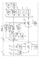
- FIG. 1 is a block diagram illustrating the configurations of a camera and a lens in at least one embodiment.
- FIG. 2 is a diagram describing a pixel configuration of an image plane phase difference detection system in at least one embodiment.
- FIG. 3 is a flowchart illustrating a video shooting process in at least one embodiment.
- FIG. 4 is a flowchart illustrating AF restart determination in at least one embodiment.
- FIG. 5 is a flowchart illustrating a rack focus AF process in at least one embodiment.
- FIG. 6 is a flowchart illustrating a lens drive speed setting in at least one embodiment.
- FIG. 7 is a flowchart illustrating a lens drive process in at least one embodiment.
- FIG. 8 is a flowchart illustrating a moving subject determination method in at least one embodiment.
- FIGS. 9A and 9B are tables of thresholds used for moving subject determination in at least one embodiment.
- FIG. 10 is a flowchart illustrating a subject change determination method in at least one embodiment.
- FIGS. 11A to 11C are tables of thresholds used for subject change determination in at least one embodiment.
- FIG. 12 is a flowchart illustrating the determination of a focus mode in at least one embodiment.
- FIGS. 13A and 13B are diagrams related to the focus mode in at least one embodiment.
- FIG. 14 is a flowchart illustrating a tracking AF process in the embodiment.
- FIG. 15 is a flowchart illustrating a method for a stop determination process in at least one embodiment.
- FIG. 16 is a diagram illustrating stop determination in at least one embodiment.
- FIG. 1 is a block diagram illustrating the configurations of a lens and a main body of an interchangeable-lens camera in a first embodiment of the disclosure.
- the embodiment is configured including a lens 10 and a camera 20 .
- a lens control unit 106 that controls the overall operation of the lens communicates information with a camera control unit 212 that controls the operation of the entire camera.
- the lens 10 includes a fixed lens 101 , a aperture 102 , a focus lens 103 , a aperture drive unit 104 , a focus lens drive unit 105 , a lens control unit 106 , and a lens operating unit 107 .
- the fixed lens 101 , the aperture 102 , and the focus lens 103 are a shooting optical system of the embodiment.
- the aperture 102 is driven by the aperture drive unit 104 .
- the lens control unit 106 controls the aperture 102 via the aperture drive unit 104 to control the amount of light incident on an imaging element 201 described below.
- the focus lens 103 is driven by the focus lens drive unit 105 .
- the lens control unit 106 controls the position of the focus lens 103 via the focus lens drive unit 105 to control the position of focus of an image formed on the imaging element 201 described below.
- the lens control unit 106 performs control in accordance with the user operation.
- the lens control unit 106 controls the aperture drive unit 104 and the focus lens drive unit 105 in accordance with a control command/control information received from the camera control unit 212 described below.
- the lens control unit 106 transmits lens control information to the camera control unit 212 .
- the camera 20 is configured in such a manner as to be able to acquire an imaging signal from light rays that have passed through the shooting optical system of the lens 10 .
- the imaging element 201 is configured by a CCD or CMOS sensor.
- the light rays that have passed through the shooting optical system forms an image on a light receiving surface of the imaging element 201 to be photoelectrically converted by photodiodes into signal charge in accordance with the amount of incident light.
- the signal charge accumulated in each photodiode is sequentially read, as a voltage signal in accordance with the signal charge, from the imaging element 201 on the basis of a driving pulse given from a timing generator 215 in accordance with a command of the camera control unit 212 .
- the imaging element 201 includes two photodiodes in one pixel portion to perform focus detection in an image plane phase difference detection system ( FIG. 2 ). It is designed in such a manner that light rays are separated by a microlens (not illustrated), and the light rays having parallax are received by the two photodiodes to remove two signals for imaging and AF.
- a signal (A+B) obtained by adding the signals of the two photodiodes is an imaging signal.
- the photodiode signals (A and B) are two (a pair of) image signals for AF.
- a correlation between the two image signals is calculated by an AF signal processing unit 204 described below, on the basis of the signals for AF, to calculate the amount of image displacement and various kinds of reliability information.
- the imaging signal and the signals for AF read from the imaging element 201 are inputted into a CDS/AGC/AD converter 202 to perform correlated double sampling to remove reset noise, gain adjustment, and signal digitization.
- the CDS/AGC/AD converter 202 outputs the imaging signal to an image input controller 203 and the signals for AF to the AF signal processing unit 204 .
- the image input controller 203 stores, in an SDRAM 209 , the imaging signal outputted from the CDS/AGC/AD converter 202 .
- the imaging signal stored in the SDRAM 209 is displayed on a display unit 206 by a display control unit 205 via a bus 21 .
- the imaging signal is recorded by a recording medium control unit 207 in a recording medium 208 .
- a control program to be executed by the camera control unit 212 various kinds of data necessary for control, and the like are stored in a ROM 210 connected via the bus 21 .
- Various kinds of setting information related to the operation of the camera 20 such as user setting information, and the like are stored in a flash ROM 211 .
- the AF signal processing unit 204 calculates a correlation on the basis of the two image signals for AF outputted from the CDS/AGC/AD converter 202 , and calculates the amount of image displacement and reliability information (such as a two-image matching level, two-image steepness, contrast information, saturation information, and defect information).
- the calculated amount of image displacement and reliability information are outputted to the camera control unit 212 .
- the camera control unit 212 notifies the AF signal processing unit 204 of changes in settings for calculating them on the basis of the acquired amount of image displacement and reliability information. For example, if the amount of image displacement is large, an area for which a correlation is calculated is set large, or the kind of band-pass filter is changed according to the contrast information.
- a face detection unit 216 performs a known face detection process on the imaging signal to detect the face of a person on a shooting screen.
- the detection result is transmitted to the camera control unit 212 .
- the camera control unit 212 transmits information to the AF signal processing unit 204 in such a manner as to add a face frame to an area including the face on the shooting screen on the basis of the detection result.
- There is a main face determination processing unit that determines the order of priority according to face positions and sizes, or at the user's instruction, when the face detection unit has detected faces of a plurality of persons.
- the face that has been judged by the main face determination processing unit to have the highest priority is assumed to be the prime face.
- a determination is made in such a manner as to give the highest priority to a face selected by the user's instruction, and then give a higher priority as the position of a face is closer to the center of the screen and as the size of a face is larger.
- the method is not limited to the above method.
- the following method has been disclosed as the face detection process. It is a method in which a skin color area is detected from gradation colors of pixels presented in image data to detect a face on the basis of a matching level with a face contour plate that has been prepared in advance, or a method in which features of the face such as the eyes, nose, and mouth are extracted using a known pattern recognition technique to detect a face.
- the method for the face detection process is not limited to the above-mentioned methods, and can be any method.
- a tracking processing unit 217 acquires images having different times from the imaging signals outputted from the CDS/AGC/AD converter 202 , extracts features in the images, and searches for and tracks an area where the features are similar. Upon an initial operation where a reference image has not been registered, a partial area within the image is set as the reference image on the basis of information of the camera operating unit 214 and information on the detection result of the face detection unit 216 . Color information is then extracted from the reference image to be registered as a feature of a subject to track. The matching process between the image of the imaging signal and the reference image in the current frame is performed on the basis of the extracted features of the tracking target subject.
- an area, which has the highest degree of correlation with the reference image, of the image of the imaging signal in the current frame is extracted by the matching process as a target specific area. It is then determined whether or not to continue tracking, depending on whether or not the degree of correlation is high. Moreover, the tracking state based on the degree of correlation is calculated as reliability, is transmitted to the camera control unit 212 , and is used as a parameter for AF control.
- the camera control unit 212 exchanges information with the entire inside of the camera 20 to perform control.
- the camera control unit 212 not only performs processing in the camera 20 but also executes various camera functions operated by the user, such as turning-on/off of the power, setting changes, start of recording, start of AF control, and checking of recorded video, in accordance with an input from the camera operating unit 214 .
- the camera control unit 212 exchanges information with the lens control unit 106 in the lens 10 , transmits a lens control command/control information, and acquires lens internal information.
- the camera 20 includes the recording medium 208 and the SDRAM 209 .
- a video recording switch is pressed to start and stop recording video.
- the recording may be started and stopped by another system such as a changeover switch.
- the AF signal processing unit 204 When it is instructed with the video recording switch or the like to record video, the AF signal processing unit 204 performs an AF area calculation process in S 505 . Execution then proceeds to S 506 .
- the AF area calculation process is a process of setting an area on the image plane to acquire a signal used for focus detection.
- the AF signal processing unit 204 performs a focus detection process in S 506 . Execution then proceeds to S 507 .
- the amount of defocus and the reliability information are acquired by focus detection in the image plane phase difference detection system.
- the amount of defocus is detected on the basis of the amount of image displacement based on the above-mentioned pair of image signals.
- the amount of defocus in the embodiment is information indicating how much the focus lens 103 is controlled to be driven in which of the closest distance direction and the infinite distance direction.
- the reliability information is an index that indicates how reliable the amount of image displacement is.
- Reliability can be defined by the steepness and a matching level fnclvl of two images of the image signals A and B (hereinafter referred to as the two-image matching level).
- the focus detection process of the image plane phase difference method is described in detail in, for example, Japanese Patent Laid-Open No. 2015-87704.
- S 507 is a process of the camera control unit 212 referring to the responsiveness setting and speed setting of the focus lens 103 set by the user to control the drive of the focus lens 103 .
- the user can set the speed by selecting the drive speed of the focus lens 103 on, for example, a menu screen (not illustrated) of the camera.
- the drive speed is selected from seven levels of +2 to ⁇ 4.
- the camera control unit 212 refers to a speed parameter corresponding to the drive speed selected by the user to set the drive speed of the focus lens 103 using the amount of defocus detected by the AF signal processing unit 204 .
- the speed parameter is the count of the vertical synchronization signals (60 Hz).
- Responsiveness is a measure of the response speed of the drive of the focus lens 103 .
- One of the indexes indicating responsiveness is the length of the response time being the time required to drive the focus lens 103 . As the response time is increased, responsiveness is reduced. As the response time is reduced, responsiveness is increased.
- responsiveness setting of the embodiment responsiveness is selected from seven levels of +3 to ⁇ 3.
- the camera control unit 212 refers to the response time of the focus lens 103 corresponding to the responsiveness selected by the user, and changes the time required to restart in S 512 and the time required to start focusing when the subject has been switched in a tracking drive mode in S 516 .
- the camera control unit 212 performs a moving subject determination process in S 508 .
- the moving subject determination process is a process of the camera control unit 212 determining whether or not the subject that is being shot is moving in an optical axis direction. The details are described below with reference to FIGS. 8 and 9A and 9B
- S 509 is a process of the camera control unit 212 determining whether or not the subject has been changed. The details are described below with reference to FIGS. 10 and 11A to 11C .
- S 510 is a process of the camera control unit 212 determining a focus mode to be set. The details are described below with reference to FIGS. 12 and 13A and 13B .
- the camera control unit 212 determines whether or not the focus mode determined in S 510 is default. If the focus mode is default, execution moves to S 512 .
- S 512 is a process of AF restart determination performed by the camera control unit 212 . The details are described below with reference to FIG. 4 .
- the camera control unit 212 performs control in such a manner as to perform an AF process in rack focus mode. The details are described below with reference to FIG. 5 .
- the camera control unit 212 determines the presence or absence of a subject change focus stop flag (described below in FIG. 10 ). If the flag is off, execution moves to S 516 . If the flag is not off, execution moves to S 517 .
- the camera control unit 212 performs control in such a manner as to stop the lens without performing the AF process.
- the subject change focus stop flag is referred to. Accordingly, when it is determined whether or not the subject has been switched to another subject, the camera control unit can perform control in such a manner as to stop the drive of the focus lens 103 .
- the AF process in tracking mode is performed. The details are described below with reference to FIG. 14 .
- This flow is repeatedly executed until an instruction to stop video shooting is issued.
- FIG. 13A is a diagram illustrating the relationship between the focus modes.
- FIG. 13B is a diagram illustrating the kinds of focus mode and their characteristics.
- the default mode is a mode to which a transition is made from another focus mode at the time of stopping focusing (when it is determined to have achieved focus and the drive of the focus lens 103 is stopped).
- the rack focus mode (third mode) is a mode to set the response time and drive speed for driving the focus lens 103 , as instructed by the user, and drive the focus lens 103 in accordance with the settings. If there is no user's instruction, the camera control unit 212 performs control in such a manner as to drive the focus lens 103 in accordance with the default settings.
- the tracking mode is a focus mode to perform control in such a manner as to cause the focus lens 103 to track a moving subject when the moving subject has been detected as a subject. Accordingly, the drive speed of the focus lens 103 is set at a speed in accordance with the moving subject.
- the camera control unit 212 variably controls the drive speed of the focus lens on the basis of the detected amount of defocus. The camera control unit 212 performs control in such a manner as to drive the focus lens faster if the detected amount of defocus is relatively larger than if the detected amount of defocus is smaller.
- the transition of the focus modes is described with reference to FIG. 13A . If it is determined by moving subject determination in default mode that a subject is a moving subject, a transition is made to the tracking mode ( 2505 ). Moreover, also if it is determined by the moving subject determination in rack focus mode that a subject is a moving subject, a transition is made to the tracking mode ( 2504 ).
- a transition is made from the default mode to the rack focus mode ( 2502 ).
- the camera control unit 212 acquires the amount of defocus calculated in S 506 . Moreover, the camera control unit 212 acquires the current lens position of the focus lens 103 via the lens control unit 106 .
- a target lens position is calculated from the amount of defocus and the current lens position that are acquired in S 1401 .
- the following equations are used for this calculation:
- the drive amount [pulses] the amount of defocus [mm]+a pulse conversion coefficient [pulses/mm] (2)
- the target lens position [pulses] the current lens position [pulses]+the drive amount [pulses] (3).
- This calculation is an example of the conversion of an out-of-focus amount (here, the amount of defocus) on the image plane of the imaging element 201 into the lens drive amount of the focus lens 103 .
- an out-of-focus amount here, the amount of defocus
- any calculation method other than the above calculation can be accepted.
- the camera control unit 212 detects the continuity of the target lens position (the actual value/the average) of the focus lens 103 in the infinite distance direction or closest distance direction. In the embodiment, let the direction toward the infinite end be a plus direction, and let the direction toward the closest end be a minus direction. How many times it is continuously increased/reduced in the infinite distance direction/closest distance direction is counted.
- S 1404 is a process of setting a threshold of the continuous number of times.
- the threshold is changed according to the aperture and the kind of value used for the calculation of the target lens position (the actual value/the average).
- the threshold is reduced as compared to one at a large f-number. This is because the depth of focus becomes shallower if the f-number is small than if the f-number is large; therefore, a blur becomes conspicuous. The easiness to start the moving subject determination allows a reduction in the occurrence of unnatural blurring. Accordingly, the quality of video can be maintained. Moreover, the threshold is made larger if the amount of defocus used for the calculation of the target lens position of the focus lens 103 is the actual value than if the average is used. This is because more stable detection can be achieved if the average is used than if the actual value is used.
- the moving subject determination is not made. This is because the depth of focus of the subject is sufficiently deep; therefore, even if the moving subject determination is not made, blurring hardly occurs. If, for example, the f-number is larger than F11, the threshold is set in such a manner that the continuous number of times is not equal to or greater than the threshold.
- S 1405 is a process of determining whether or not the continuous number of times has exceeded the threshold. If the continuous number of times has exceeded the threshold, execution proceeds to S 1406 . If not, execution proceeds to S 1413 . In the embodiment, if at least one of the target lens position calculated using the actual value and the target lens position calculated using the average is equal to or greater than its threshold set in S 1404 , it is determined that the subject is a moving subject. Execution then proceeds to S 1406 . If both of the target lens position calculated using the actual value and the target lens position calculated using the average are less than their thresholds set in S 1404 , it is determined that the subject is not a moving subject. Execution then proceeds to S 1413 .
- S 1406 it is determined whether or not focusing is being stopped (in other words, whether or not it is in default mode). If focusing is being stopped, execution proceeds to S 1407 . If not, execution proceeds to S 1409 .
- S 1409 it is determined whether or not the focus mode is the rack focus mode. If it is the rack focus mode, execution proceeds to S 1410 . If not, the focus mode is the tracking mode. Therefore, the process of this flow is terminated to continue the tracking mode.
- the camera control unit 212 performs control in S 1407 in such a manner as to set a predetermined fifth value as the threshold for the moving subject determination, and performs control in S 1410 in such a manner as to set a predetermined sixth value as the threshold for the moving subject determination.
- the threshold (here, the predetermined fifth value) is changed according to the aperture and the focal length as illustrated in an example in FIG. 9B .
- the predetermined fifth value is reduced if the f-number is small as compared to if the f-number is large.
- the predetermined fifth value is increased if the focal length is long as compared to if the focal length is short. This is because as the depth of focus becomes shallower, a blur becomes more conspicuous; accordingly, it becomes easier to make the moving subject determination to maintain the quality of video.
- the moving subject determination can be made more quickly when a moving subject moves (responsiveness to a subject of the focus lens 103 is improved).
- the moving subject determination is made for a subject that is not a moving subject (the tracking stability of the focus lens 103 for a subject is reduced).
- it is required to set the predetermined fifth value, considering the balance between stability and responsiveness.
- the f-numbers and focal lengths at which the moving subject determination is not made are set.
- the moving subject determination is not made. This is because the depth of focus of the subject is sufficiently deep; therefore, blurring hardly occurs even if the moving subject determination is not made.
- the predetermined fifth value is set in such a manner as to avoid the amount of defocus increasing to or above the predetermined fifth value.
- the predetermined sixth value is set at a smaller value if the f-number is small than if the f-number is large, as with the predetermined fifth value. Moreover, the predetermined sixth value is set at a larger value if the focal length is long than if the focal length is short.
- the threshold is changed according to whether or not the moving direction of the subject and the drive direction of the focus lens 103 agree with each other. If the moving direction of the subject and the drive direction of the focus lens 103 do not agree with each other, the subject and the focus lens 103 moves/is driven in opposing directions in the optical axis direction. In this case, both of the focus lens 103 and the subject continue moving, the time required for the focus lens 103 to go within the focus range of the subject becomes very short. Accordingly, the time required to switch from the rack focus mode to the tracking mode may be too short. Therefore, if the moving direction of the subject and the drive direction of the focus lens 103 do not agree with each other, the predetermined sixth value is set large to secure the switching timing.
- the determination is made with the same threshold as the one for the normal focusing stop.
- the threshold one obtained by multiplying the threshold determined in FIG. 9B by a designated magnification is set as the threshold of the rack focus mode.
- a coefficient of a factor of 1.5 is multiplied if the lens and the subject move in opposite directions.
- S 1412 is a process of a case where a subject has been determined to be a moving subject (the moving subject determination has been made).
- a moving subject determination flag is turned on to terminate the process.
- the moving subject determination flag is turned on in S 1412 . The turning-on of the moving subject flag makes a transition to the tracking mode in a focus mode determination process ( FIG. 12 ) described below.
- the camera control unit 212 can perform control in such a manner as to prevent a sudden change in the blurred state. Consequently, the quality of an image can be improved when a moving subject is tracked.
- S 1413 is a process for the time when the moving subject determination has not been made, or for the case where a transition has already been made to the tracking mode.
- the moving subject determination flag is turned off to terminate the process.
- the moving subject determination flag is turned off here to continue driving the focus lens 103 in rack focus mode in the focus mode determination process ( FIG. 12 ) described below. Consequently, the camera control unit 212 can perform control in such a manner as to prevent a sudden change in focus state due to the switching of the focus state that is an out-of-focus state to the tracking mode.
- the subject change determination process is a process of determining whether or not a subject to track has been changed in tracking mode.
- the subject change determination process of determining whether or not a subject is a subject that is an original tracking target is performed in tracking mode; accordingly, the focus lens 103 is prevented from tracking a subject different from a tracking target subject. If, for example, a subject different from the tracking target subject crosses, the camera control unit 212 performs control in such a manner that the drive of the focus lens 103 is stopped not to perform the tracking operation on the crossing subject. The details are described below. On the other hand, even if a subject different from a subject that is an original tracking target is captured, when it can be determined that a user has changed the subject intentionally, the camera control unit 212 controls the drive in such a manner as to cause the focus lens 103 to track the crossing subject. The flow of FIG. 10 is described below as an example of the flow that achieves the control.
- S 2201 is a process of determining whether or not the current focus mode is the tracking mode. If the current focus mode is the tracking mode, the camera control unit 212 performs control in such a manner as to proceed to S 2202 to determine the change of the subject. If the current focus mode is not the tracking mode, the camera control unit 212 performs control in such a manner as to proceed to S 2217 and terminate the process of the flow.
- S 2202 is a process of storing the amount of defocus in the SDRAM 209 .
- the camera control unit 212 calculates a distance between the focus and the subject on the basis of the amount of defocus calculated by the AF signal processing unit 204 in S 506 .
- the distance between the focus and the subject is one obtained by converting the amount of defocus into a distance on the subject side that indicates how far apart a subject position where the subject is in focus and an actual subject position are.
- the subject distance is a distance from the subject position where the subject is in focus to the focus lens 103 .
- S 2205 is a process of the camera control unit 212 setting thresholds for determining whether or not to have changed a subject. There are three thresholds.
- Threshold 1 (a predetermined first value): a threshold for the amount of change in the amount of defocus
- Threshold 2 (a predetermined second value): a threshold for the ratio of the distance between the focus and the subject to the depth of field
- Threshold 3 (a predetermined third value): a threshold for the distance between the focus and the subject
- Threshold 1 is a threshold for the amount of change between the amount of defocus detected this time and the amount of defocus detected last time. This is a threshold used to detect a sudden change in subject. As an example in the embodiment, threshold 1 is obtained by comparing an average DEF_Diff_AVE of three amounts of change in the amount of defocus and the present amount of change in the amount of defocus, DEF_Diff.
- threshold 1 of the embodiment is a threshold of a factor of 1.5 or more. This is because it is conceivable that when the amount of defocus changes by a factor of 1.5, the subject is highly likely to have been changed.
- Threshold 2 is a threshold for the ratio of the distance between the focus and the subject to the depth of field, and is a threshold for determining how much is blurred.
- a multiple of the depth of field is set as threshold 2.
- the threshold is changed according to the depth of focus as in FIG. 11A . As the f-number is reduced, the depth of focus is increased. Accordingly, a variation in the focus detection result becomes easy to occur. As the depth of focus is increased, threshold 2 is increased as compared to a case where the depth of focus is not deep. Accordingly, it is possible to prevent an erroneous determination resulting from the variation in the focus detection result.
- the subject change determination may not be made.
- the threshold may be set in such a manner that the subject change determination is not made. In this case, for example, the threshold is set in such a manner that the ratio of the distance between the focus and the subject to the depth of field does not exceed the threshold.
- Threshold 3 is a threshold for the distance between the focus and the subject, and is a threshold for detecting how far apart the focus and the subject are. In the case of the embodiment, a distance of 1 m between the focus and the subject is set as the threshold as an example. This indicates that if a subject that is 1 m or more apart from a subject tracked is detected, the subject has been changed. If threshold 3 is increased, trackability for the subject that is the original tracking target is improved. However, it becomes difficult to determine the change of the subject. In other words, the possibility of being able to avoid performing the focusing operation on a subject crossing between a subject being an original tracking target and a camera (also referred to as the crossing subject) during the shooting of a moving subject is increased.
- threshold 3 it becomes easy to determine that the subject has been changed from the subject that is the original tracking target.
- the possibility of being able to avoid performing the focusing operation on a subject crossing between a subject being an original tracking target and a camera (also referred to as the crossing subject) during the shooting of the moving subject is increased.
- the trackability of the focus lens 103 for a moving subject ends up decreasing.
- threshold 3 of the distance between the focus and the subject is changed according to the moving speed. Accordingly, the presence or absence of the change of the subject can be determined with higher accuracy. For example, threshold 3 is set larger if the moving speed of the subject is high than if the moving speed of the subject is low. Accordingly, it is possible to prevent determining erroneously that the subject has been changed although capturing the same subject. Threshold 3 is set smaller if the moving speed of the subject is low than if the moving speed is high. Accordingly, if the subject has been changed, it becomes easy to track the changed subject.
- thresholds 2 and 3 The relationship between thresholds 2 and 3 described above is described with reference to FIG. 11C .
- threshold 2 is indicated by a line 2301 .
- Threshold 3 is indicated by a line 2302 (1 m in the embodiment).
- Threshold 3 is the threshold for a change in distance to a subject and accordingly is fixed irrespective of the subject distance. However, if the depth of field is increased, a variation occurs in the focus detection result. Hence, a variation of 1 m or more occurs in a case of a subject at a long range. Therefore, both of thresholds 2 and 3 are also used for a subject at a long range to determine the change of the subject with accuracy.
- Threshold 2 is the threshold related to the depth of field and therefore changes according to the subject distance. Threshold 2 changes as indicated by the line 2301 , and is increased on the long range side, and is reduced on the short range side. Hence, in terms of a subject at a long range, even if the distance between the focus and the subject is equal to or greater than threshold 3, when the ratio of the distance between the focus and the subject to the depth of field is less than threshold 2, the camera control unit 212 determines that the subject has not been changed. Consequently, it is possible to prevent an erroneous determination resulting from a variation in the focus detection result.
- threshold 2 the depth of field used for threshold 2 is reduced on the short range side. If only threshold 2 is set, the threshold becomes too small for the movements of the subject. Hence, threshold 3 is used on the short range side to enable the prevention of an erroneous determination.
- thresholds 2 and 3 when the conditions of thresholds 2 and 3 are exceeded, it is judged that the subject has been changed. Accordingly, the presence or absence of a change in subject can be stably determined both at the long range and the short range.
- the thresholds may be changed in areas where the subject distance is shorter than a predetermined distance. A description is given with reference to FIG. 11B .
- the area 2303 indicates a subject distance of less than 3 m (less than a predetermined seventh value) as an example in the embodiment.
- the camera-to-subject distance is short and there is little influence of crossing.
- the resolution/accuracy of distance information acquired from the lens is high.
- the distance to the subject is reliable.
- the condition of threshold 3 may be changed between a case where the subject distance is equal to or greater than the predetermined seventh value and a case where the subject distance is less than the predetermined seventh value. In this case, if the subject distance is equal to or greater than the predetermined seventh value, threshold 3 is set at a fixed value irrespective of the subject distance.
- threshold 3 is set at a value smaller than if the subject distance is equal to or greater than the predetermined seventh value. Moreover, the camera control unit 212 sets the threshold in such a manner that threshold 3 is increasingly reduced (but not to zero) from a subject distance of 3 m (the predetermined seventh value) to (a predetermined eighth value) as indicated by a line 2305 . Moreover, at a subject distance of less than 1 m (less than the predetermined eighth value), it is set in such a manner that threshold 3 is zero at a subject distance of 1 m.
- the area 2304 indicates a macro-shooting area at a subject distance of 1 m (less than the predetermined eighth value). For example, a depth of field of less than 1.5 cm (less than a predetermined tenth value) conditions a determination in this area in the embodiment.
- the change of a subject cannot be detected if threshold 3 remains at 1 m.
- the depth of field is shallow. Accordingly, the change of a subject is determined too sensitively at the conventional threshold 2; therefore, the number of erroneous determinations increases. From the above reasons, threshold 2 is set at a larger value in the macro-shooting area 2304 than in other area as indicated by a line 2306 , and threshold 3 is set at a value (0 m) that has no influence.
- thresholds for determining the change of a subject are changed according to the subject distance, the depth of field, and the f-number. Accordingly, a determination can be stably made.
- S 2206 it is determined whether or not the amount of change in the amount of defocus is equal to or greater than threshold 1 (equal to or greater than the predetermined first value). If the amount of change in the amount of defocus is equal to or greater than threshold 1, execution proceeds to S 2207 . On the other hand, if the amount of change in the amount of defocus is less than threshold 1 (less than the predetermined first value), execution proceeds to S 2209 .
- S 2207 it is determined whether or not the ratio of the distance between the focus and the subject to the depth of field is equal to or greater than threshold 2 (equal to or greater than the predetermined second value), and whether or not the distance between the focus and the subject is equal to or greater than threshold 3 (equal to or greater than the predetermined third value). If so, it is determined that the subject has been changed, and execution proceeds to S 2208 . If not, execution proceeds to S 2211 .
- the camera control unit 212 turns on the subject change focus stop flag to perform control in such a manner as to stop the drive of the focus lens 103 , and terminates the process.
- S 2210 it is determined whether or not the ratio of the distance between the focus and the subject to the depth of field is equal to or greater than threshold 2 (equal to or greater than the predetermined second value), and whether or not the distance between the focus and the subject is equal to or greater than threshold 3 (equal to or greater than the predetermined third value). If so, it is determined that the change (switching) of the subject continues, and execution proceeds to S 2212 . If not, execution proceeds to S 2211 .
- the camera control unit 212 turns off the subject change focus stop flag to perform control in such a manner as to continue the drive of the focus lens 103 , determining that there was no change in subject, and terminates the process.
- S 2213 it is determined whether or not the count is equal to or greater than predetermined second time of response time. If the count is equal to or greater than the predetermined second time, execution proceeds to S 2214 . If not, execution proceeds to S 2216 .
- the predetermined second time of the response time is the value set in S 507 .
- S 2213 is a process of determining whether or not the count exceeds the response time.
- the camera control unit 212 turns on a subject change focus drive flag to perform control in such a manner as to restart the drive of the focus lens 103 , and terminates the process.
- the camera control unit 212 determines that the subject has been switched. Consequently, even when, for example, the distance between an imaging apparatus and a subject is long, and a variation may occur in the focus detection result of the phase difference detection system, whether or not the subject has been switched can be determined with higher accuracy than the known technology.
- the focus mode determination process is described with reference to FIG. 12 .
- the camera control unit 212 determines whether or not initialization has already been performed. If initialization has not been performed, the focus mode is set in the rack focus mode in S 2402 . Execution proceeds to S 2403 . If not, execution proceeds to S 2403 not via S 2402 .
- the initialization process is a process that is performed whenever the shooting mode or the like is switched.
- the camera control unit 212 determines whether or not the focus mode is the default mode. If the focus mode is the default mode, execution proceeds to S 2404 . If not, execution proceeds to S 2409 .
- the camera control unit 212 determines the presence or absence of the moving subject determination flag. If the moving subject determination flag is on, execution proceeds to S 2405 .
- the focus mode is set in the tracking mode to terminate the control.
- the camera control unit 212 determines the presence or absence of a focusing stop flag. If the focusing stop flag is off, execution proceeds to S 2407 .
- the focus mode is set in the rack focus mode to terminate the control. If not, the focus mode is set in the default mode in S 2408 to terminate the control.
- the camera control unit 212 determines whether or not the focus mode is the rack focus mode. If the focus mode is the rack focus mode, execution proceeds to S 2410 . If not, execution proceeds to S 2415 . In S 2410 , the presence or absence of the moving subject determination flag is determined. If the moving subject determination flag is on, execution proceeds to S 2411 . The focus mode is set in the tracking mode to terminate the control. If not, execution proceeds to S 2412 . The camera control unit 212 determines the presence or absence of the focusing stop flag. If the focusing stop flag is off, execution proceeds to S 2413 . The focus mode is set in the rack focus mode to terminate the control. If not, the focus mode is set in the default mode in S 2414 to terminate the control.
- the current focus mode is the tracking mode; accordingly, the presence or absence of the subject change focus drive flag is determined. If the focus drive flag is off, execution proceeds to S 2416 .
- the focus mode is set in the tracking mode to terminate the control. If not, execution proceeds to S 2417 .
- the camera control unit 212 determines the presence or absence of a tracking stop determination flag. If the tracking stop determination flag is off, execution proceeds to S 2418 .
- the focus mode is set in the rack focus mode to terminate the control. If not, the focus mode is set in the default mode in S 2419 to terminate the control.
- the AF restart determination is a process of the camera control unit 212 determining whether or not to drive the focus lens again from the state where the focus lens has achieved focus and is stopping.
- the camera control unit 212 judges whether or not the amount of default calculated is smaller than predetermined times the depth of focus (a predetermined fourth value). If the amount of defocus is less than the predetermined fourth value, execution proceeds to S 702 . If the amount of defocus is equal to or greater than the predetermined fourth value, execution proceeds to S 704 .
- the threshold (the predetermined fourth value) of the amount of defocus set in S 701 is assumed to be a value that considers to make the restart easy when a main subject is changed, and to make an inadvertent restart hard when the main subject is not changed. As an example in the embodiment, one times the depth of focus that allow a blur of the main subject to be perceptible is set at the predetermined fourth value.
- S 702 it is judged whether or not the reliability calculated is a value higher than a predetermined value. If it indicates a higher value, execution proceeds to S 703 . If it indicates a lower value, execution proceeds to S 704 .
- the threshold of reliability set in S 702 is set at, for example, a value indicating such low reliability that it is difficult to rely on the defocus direction as a value regarded that the main subject has been changed. For example, it may be similar to a predetermined value ⁇ of S 901 . In this manner, whether or not a main subject has been changed is judged using the thresholds set in S 701 and S 702 .
- an AF restart counter is reset. Execution then proceeds to S 705 .
- the AF restart counter counts up. Execution then proceeds to S 705 .
- the AF restart counter counts up to prepare for the restart of AF. If the detected amount of defocus is less than the predetermined fourth value, and high reliability is maintained, the AF restart counter is reset in S 703 to cause the focus lens 103 to continue stopping.
- an AF restart threshold is set. Execution then proceeds to S 706 .
- the camera control unit 212 performs the AF restart threshold setting of S 705 , using the response time determined in S 507 as the threshold.
- the camera control unit 212 judges whether or not the AF restart counter that counted up in S 704 is larger than the threshold set in S 705 .
- the rack focus AF process is a process of driving the focus lens in a state where focusing is not stopped, and determining whether or not to stop focusing.
- S 801 it is judged whether or not the amount of defocus is within the depth of focus, and whether or not reliability indicates a higher value than the predetermined value. If this condition is applicable, execution proceeds to S 802 . If not, execution proceeds to S 803 .
- the threshold used in S 801 is set at one times the depth of focus. However, the threshold used in S 801 may be set larger or smaller if needed.
- the camera control unit 212 turns on the focusing stop flag to terminate the process.
- S 803 the camera control unit 212 sets the lens drive speed. Execution proceeds to S 804 .
- the details of the lens drive speed setting of S 803 are described below with reference to FIG. 6 .
- the camera control unit 212 performs control in such a manner as to perform a lens drive process to terminate the process of this flow.
- the details of the lens drive process of S 804 are described below with reference to FIG. 7 .
- the camera control unit 212 judges whether or not reliability is less than the predetermined value ⁇ . If reliability is lower than the predetermined value ⁇ , execution proceeds to S 902 . If reliability is equal to or greater than the predetermined value ⁇ , execution proceeds to S 905 .
- the predetermined value ⁇ is set at a value at which it is possible to determine that at least the defocus direction is reliable.
- the camera control unit 212 judges whether or not the search drive shift counter is equal to or greater than a set predetermined value. If the search drive shift counter is equal to or greater than the predetermined value, execution proceeds to S 904 . If the search drive shift counter is not equal to or greater than the predetermined value, execution proceeds to S 906 . In S 904 , a search drive flag is turned on. Execution then proceeds to S 906 .
- the camera control unit 212 determines whether or not the focus mode is the rack focus mode. If the focus mode is the rack focus mode, execution proceeds to S 907 . If not, execution proceeds to S 912 .
- the camera control unit 212 determines whether or not the search flag is on. If the search flag is on, a speed for a search is set in S 908 . In terms of the setting of a speed for a search, the speed is changed, using information from an unillustrated speed setting menu, in stages in accordance with the menu.
- the search drive is a focusing operation that is performed at a level of reliability that indicates that the amount of defocus is not reliable.
- the search drive is configured as follows: The camera control unit 212 performs control in such a manner as to set a defocus direction irrespective of the amount of defocus and drive the focus lens at the set speed in the set direction; The search drive shift counter counts up to determine whether or not the search drive shift counter is equal to or greater than the predetermined value; Only when it can be judged that there is a possibility that reliability is continuously low and the subject is out of focus, the search drive can be performed.
- the search drive is drive that does not use the amount of defocus. Accordingly, focusing that temporarily increases the level of blurring may be performed.
- a user sets responsiveness in such a manner as to prevent an immediate shift to the search drive even if reliability is reduced; accordingly, it is possible to prevent inadvertent search drive.
- S 909 it is determined whether or not the moving direction of a moving subject in the closest distance direction or infinite distance direction and the drive direction of the focus lens agree with each other. If they do not agree with each other, execution proceeds to S 910 . If they agree with each other, execution proceeds to S 911 .
- a normal speed setting is performed.
- the normal speed setting information from the unillustrated speed setting menu is used to change the speed in stages in accordance with the menu.
- the set drive speed of the focus lens 103 is a speed that allows the focus lens 103 to catch up with the moving subject.
- a difference between the current focus lens position and the previous focus lens position is compared with a difference between the current target lens position and the previous target lens position.
- the current target lens position is a target lens position based on the current focus lens position and the current focus detection result.
- the previous target lens position is a target lens position based on the previous focus lens position and the previous focus detection result.
- the camera control unit 212 determines that it is a speed that allows the focus lens 103 to catch up with the moving subject. If the camera control unit 212 has determined that it is a speed that allows catching up (a speed that allows tracking of the moving subject), execution proceeds to S 910 . If the difference between the current focus lens position and the previous focus lens position is less than the difference between the current target lens position and the previous target lens position, the camera control unit 212 determines that it is a speed that does not allow the focus lens 103 to catch up with the moving subject. If the camera control unit 212 has determined that it is a speed that does not allow catching up (the speed is too low to track the moving subject), execution proceeds to S 912 .
- the moving subject is moving at the speed that does not allow the focus lens 103 to catch up at its currently set drive speed. Accordingly, it is a state where focus cannot be achieved. Hence, the speed is set at a higher speed than normal to make it possible to catch up with the moving subject.
- S 913 is a speed setting in tracking mode.
- a speed that agrees with the speed of the moving subject is set to make it possible to track the moving subject.
- the camera control unit 212 performs control in such a manner as to set the speed at fast speed A to quickly bring the subject into focus. If the subject's move to the closest distance direction or infinite distance direction is recognized by the moving subject determination in rack focus mode, when the directions of the moving subject and the drive of the focus lens 103 agree with each other, their speeds are compared to judge whether or not the focus lens can catch up with the moving subject. If it has been judged that it is not possible to catch up, speed C is set that is faster than normal speed B.
- S 1001 it is judged whether or not the focus mode is the rack focus mode. If the focus mode is the rack focus mode, execution proceeds to S 1002 . If the focus mode is the tracking mode, execution proceeds to S 1005 .
- S 1002 it is judged whether or not the search drive flag is on. If on, execution proceeds to S 1003 . If off, execution proceeds to S 1004 . In S 1003 to which execution proceeds if the search drive flag is on, the search drive is performed to terminate the lens drive process.
- the search drive process is a process of driving the focus lens 103 until the focus detection result where reliability can be determined to be higher than a predetermined value ⁇ is obtained if the camera control unit 212 has determined that reliability is low.
- the reliability threshold ⁇ is the same as the threshold ⁇ set in S 901 of FIG. 6 , and is a value at which at least the direction of the amount of defocus is reliable. If reliability is improved as compared to the threshold ⁇ , it can be judged that the subject is coming close to focus. Accordingly, the search drive is stopped to switch back to the control that drives the focus lens on the basis of the amount of defocus.
- the search drive flag is turned off. If the subject cannot be located, it may be controlled in such a manner as to continue the search drive without turning off the search drive flag.
- the travel distance of the subject is predicted on the basis of the amount of defocus to drive the lens.
- the tracking AF process is the AF process in tracking mode.
- the tracking AF process does not simply determine whether or not the magnitude of the latest amount of defocus is within a predetermined range (within a first range) based on the depth of focus as in, for example, S 701 and S 801 but makes a determination considering a reversed state of the drive direction of the focus lens.
- the focus position is determined on the basis of whether or not a focus detection result that the direction to drive the focus lens 103 is reversed (is changed to an opposite direction) has been obtained, or its number of times and the target lens position.
- the reverse drive is restricted.
- the reverse drive is drive that reverses the drive direction of the focus lens 103 between the closest distance direction and the infinite distance direction on the basis of the focus detection result that reverses the direction to drive the focus lens 103 (for example, the amount of defocus including information on the drive direction of the focus lens 103 ).
- the reverse drive is restricted to improve especially the quality of video upon the tracking AF.
- the camera control unit 212 determines the presence or absence of the reverse drive. If there is the reverse drive, execution proceeds to S 2609 . If not, execution proceeds to S 2604 . In the embodiment, the camera control unit 212 determines that there is the reverse drive if the amount of defocus that reverses the drive direction of the focus lens has been detected, and that there is not the reverse drive if the amount of defocus that does not reverse the drive direction of the focus lens has been detected.
- the lens drive speed setting is performed as in S 803 .
- the camera control unit 212 performs control in such a manner as to perform the lens drive process as in S 804 to terminate the process of this flow.
- the reverse timer of the embodiment is a timer that applies a restriction only for predetermined first time (described below) in such a manner as to prevent the reverse drive of the focus lens 103 if the camera control unit 212 has judged in S 2601 that there is the reverse drive.
- the camera control unit 212 determines whether or not the amount of defocus is equal to or greater than the predetermined fourth value. This is a process for changing the time required by the reverse timer to control the reverse drive, according to the amount of defocus.
- the predetermined fourth value is set at three times the depth of focus. If the amount of defocus is equal to or greater than the predetermined fourth value, execution proceeds to S 2606 . If the amount of defocus is less than the predetermined fourth value, execution proceeds to S 2607 .
- the camera control unit 212 sets the predetermined time (the predetermined first time) being a threshold of the reverse timer at time A or B.
- the camera control unit 212 performs control in such a manner as not to drive the focus lens 103 until the time set as the threshold of the reverse timer passes.
- the relationship between time A and time B is as follows: Time A ⁇ Time B
- time A is set at 0.3 seconds and time B is set at one second.
- time A is made shorter than time B is because if the amount of defocus equal to or greater than three times the depth of focus has been detected, there is a high possibility that a subject is not stopping but is making a turn. In this case, shorter time is set to make it easy to reverse the drive of the focus lens 103 in accordance with the movements of the subject.
- the amount of defocus is less than three times the depth of focus, it is highly likely because of a variation in focus detection result and a variation in the amount of defocus at the time when the subject stops moving. Accordingly, time B, which is longer than time A, is set. Consequently, the drive of the focus lens 103 is restricted in accordance with a variation in focus detection result at the time of focusing stop to improve the quality of an image. In this manner, the threshold is changed according to the drive direction; accordingly, it becomes possible to perform control in such a manner as to maintain trackability for a subject that actually makes a turn and to stop the focus lens with the quality of an image maintained if the subject being a moving subject stops.
- the camera control unit 212 determines whether or not the set predetermined first time (time A or B) has passed since the reverse timer started. If the reverse timer exceeds the predetermined first time, the camera control unit 212 permits the reverse drive of the focus lens 103 . If not, execution proceeds to S 2610 .
- the camera control unit 212 performs control in such a manner as to perform a tracking stop determination process. In other words, the camera control unit 212 performs control in such a manner as to stop the drive of the focus lens 103 until it exceeds the predetermined first time.
- the camera control unit 212 determines whether or not to stop tracking. If tracking is stopped, execution proceeds to S 2612 . The camera control unit 212 performs control in such a manner as to turn on a tracking stop flag and terminate the process of this flow. If not, execution proceeds to S 2613 . The camera control unit 212 performs control in such a manner as to turn off the tracking stop flag and terminate the process of this flow.
- the camera control unit 212 performs control in the tracking AF in tracking mode in such a manner as to change the drive of the focus lens 103 between the cases where there is and is not the reverse drive.
- the tracking AF in tracking mode it is not determined to stop focusing, depending on whether or not the detected amount of defocus is within the depth of focus.
- it is determined to stop focusing if it is determined to stop focusing if the detected amount of defocus is within the depth of focus, when the amount of defocus obtained as a result of performing focus detection on a moving subject is within the depth of focus, it is determined to have achieved focus, which ends up temporarily stopping focus adjustment.
- a time lag occurs in this time lag.
- FIG. 16 is a diagram describing an overview of the tracking stop determination.
- a case is assumed where the focus lens 103 has reached near the focus position in tracking mode.
- focus detection is performed when the focus lens 103 is near the focus position, variations occur in focus detection results in the closest distance direction and the infinite distance direction with the focus position as the center.
- This characteristic is used to allow the camera control unit 212 (a focus determination unit) to determine whether or not a subject is in focus (whether or not to stop tracking) on the basis of the number of times of reciprocation of the target lens position based on the focus detection result between infinity and the close end, and each target lens position.
- a solid line 2801 indicates an actual position of the focus lens 103 .
- a dotted line 2802 indicates a target lens position of the focus lens 103 considering the amount of defocus detected by focus detection.
- the direction of the amount of defocus detected in S 506 is not reversed with respect to the drive direction of the focus lens 103 , and the actual lens position and the target lens position agree with each other.
- the direction of the amount of defocus detected in S 506 is reversed.
- the direction of the amount of defocus detected in S 506 is reversed in tracking mode, it is controlled in such a manner as to prevent the drive of the focus lens from reversing for the predetermined time (predetermined first time).
- the actual lens position during the predetermined time is indicated by a solid line 2805 .
- variations have occurred in focus detection results. Accordingly, from the position 2803 onward in FIG. 5 , the actual lens position and the target lens position do not agree with each other.
- the camera control unit 212 makes the determination on the basis of at least three focus detection results and at least three target lens positions.
- the target lens positions 2803 , 2804 , and 2806 are detected to calculate an average position of the target lens positions of a reverse, or an average position of one target lens position at the closest end and one target lens position at infinity. Accordingly, a center position 2810 is obtained.
- a difference 2808 between the target lens position 2804 and the target lens position 2806 is determined whether or not to be within a second range (within two times the depth of focus as an example in the embodiment) (condition 1).
- a difference 2809 between a target lens position 2807 and the center position 2810 based on the latest focus detection result is determined whether or not to be within a third range (within one times the depth of focus as an example in the embodiment) (condition 2). If the above two conditions are satisfied, it is determined that the subject tracked has stopped.
- the embodiment illustrates an example where a plurality of amounts of defocus detected at the target lens position 2803 is the amounts of defocus that drive the focus lens 103 in alternatingly different directions.
- conditions 1 and 2 are simply required to be similarly determined.
- FIG. 15 is a flowchart illustrating the contents described in FIG. 16 .
- the AF signal processing unit 204 calculates the target lens position of the focus lens 103 from the amount of defocus calculated in S 506 . Execution proceeds to S 2702 .
- the camera control unit 212 counts reverses at the target lens position with respect to the drive direction of the focus lens 103 based on the previous focus detection result. Execution proceeds to S 2703 .
- the target lens position where the drive direction of the focus lens 103 is reversed (also referred to as the reverse position) is stored in the SDRAM 209 . Execution proceeds to S 2704 .
- the camera control unit 212 calculates the center position of the reverse position of the lens.
- the camera control unit 212 determines whether or not the target lens position at the closest end and the target lens position at the most infinite end are within a second range (within two times the depth of focus in the embodiment) with respect to the center position. If they are within the second range, execution proceeds to S 2707 . If they are not within the second range, execution proceeds to S 2709 . The camera control unit 212 determines not to stop tracking to terminate the process of this flow.
- the camera control unit 212 determines whether or not the target lens position is within the third range (within two times the depth of focus in the embodiment) with respect to the center position of the reverse position. If the target lens position is within two times, execution proceeds to S 2708 . The camera control unit 212 determines to stop tracking to terminate the process of this flow. If not, execution proceeds to S 2709 . The camera control unit 212 determines not to stop tracking to terminate the process.
- the camera control unit 212 determines whether or not to have achieved focus in tracking mode in S 2704 to S 2707 , on the basis of the magnitude of the amount of defocus and the reversed state of the drive direction of the focus lens based on the amount of defocus. Consequently, if the amount of defocus that has been obtained as a result of performing focus detection on a moving subject is within the depth of focus, it is possible to prevent determining that focus has been achieved although a moving subject is still moving and temporarily stopping focus adjustment. In this manner, the quality of an image at the time when a moving subject is tracked can be improved as compared to the known technology.
- the reverse count is detected on the basis of the focus detection results detected within the predetermined first time set in S 2606 or S 2607 . Instead, it may be simply determined whether or not a focus detection result within the second range is detected a second number of times or more within certain predetermined time. The second number of times is the number of times that it is possible to determine that a subject is not moving if a focus detection result within the second range is continuously detected the second number of times. If a focus detection result within the second range is detected the second number of times or more within the predetermined first time, execution proceeds to S 2705 . If not, execution proceeds to S 2709 .
- the camera control unit 212 may perform control in such a manner as to stop the focus lens 103 at the position 2807 being the nearest target lens position. Consequently, even if the solid line 2805 is not within the depth of focus at the actual focus position, focus can be achieved with higher accuracy.
- the camera control unit 212 may determine whether or not to stop tracking, on the basis of only the determination of S 2706 , without making the determination of S 2707 .
- S 2707 is not performed; accordingly, the focus lens 103 cannot be stopped at the position 2807 being the immediate target lens position.
- the focus lens 103 is fixed on the solid line 2805 to reduce the change of the blurred state. Accordingly, the quality of video can be improved.
- the previous amount of defocus may be compared with the present amount of defocus. If the amount of defocus detected this time is equal to or greater than the amount of defocus detected last time, the camera control unit 212 determines that it is a speed that does not allow the focus lens 103 to catch up with the moving subject. If the amount of defocus detected this time is less than the amount of defocus detected last time, the camera control unit 212 determines that it is a speed that allows the focus lens 103 to catch up with the moving subject.
- the determination of S 911 may not be made.
- the predetermined distance or more on the infinity side is a distance where an error occurs in focus detection to an unacceptable degree upon the determination of S 911 .
- the camera control unit 212 determines that the subject has been changed. If the ratio of the amount of defocus to the depth of focus is not equal to or greater than the predetermined eleventh value, and if the amount of defocus is not equal to or greater than the predetermined twelfth value, it is determined that the subject has not been changed.
- the camera control unit 212 may determine that the subject has been changed. If a result that the ratio of the distance between the focus and the subject to the depth of field is less than the predetermined second value and that the distance between the focus and the subject is equal to or greater than the predetermined third value is obtained less than the third number of times, it is conceivable that the cause is variations in focus detection results due to a long subject distance.
- the ratio of the distance between the focus and the subject to the depth of field is less than the predetermined second value and that the distance between the focus and the subject is equal to or greater than the predetermined third value is obtained less than the third number of times, it may be determined that the subject has not been changed.
- the present invention has been detailed on the basis of the preferred embodiment.
- the present invention is not limited to the specific embodiment, and the present invention also includes various modes within the scope that does not depart from the gist of the invention.
- the specific values are used as examples to facilitate understanding of the description, and other values may be used along the intention of the embodiment.
- other equations may be used.
- Embodiment(s) of the present disclosure can also be realized by a computer of a system or apparatus that reads out and executes computer executable instructions (e.g., one or more programs) recorded on a storage medium (which may also be referred to more fully as a ‘non-transitory computer-readable storage medium’) to perform the functions of one or more of the above-described embodiment(s) and/or that includes one or more circuits (e.g., application specific integrated circuit (ASIC)) for performing the functions of one or more of the above-described embodiment(s), and by a method performed by the computer of the system or apparatus by, for example, reading out and executing the computer executable instructions from the storage medium to perform the functions of one or more of the above-described embodiment(s) and/or controlling the one or more circuits to perform the functions of one or more of the above-described embodiment(s).
- computer executable instructions e.g., one or more programs
- a storage medium which may also be referred to more fully as a
- the computer may comprise one or more processors (e.g., central processing unit (CPU), micro processing unit (MPU)) and may include a network of separate computers or separate processors to read out and execute the computer executable instructions.
- the computer executable instructions may be provided to the computer, for example, from a network or the storage medium.
- the storage medium may include, for example, one or more of a hard disk, a random-access memory (RAM), a read only memory (ROM), a storage of distributed computing systems, an optical disk (such as a compact disc (CD), digital versatile disc (DVD), or Blu-ray Disc (BD)TM), a flash memory device, a memory card, and the like.
Landscapes
- Physics & Mathematics (AREA)
- General Physics & Mathematics (AREA)
- Engineering & Computer Science (AREA)
- Multimedia (AREA)
- Signal Processing (AREA)
- Optics & Photonics (AREA)
- Automatic Focus Adjustment (AREA)
- Studio Devices (AREA)
- Focusing (AREA)
Abstract
Description
The set speed [mm/s]=the amount of defocus [mm]+the speed parameter× 1/60 [s] (1).
The drive amount [pulses]=the amount of defocus [mm]+a pulse conversion coefficient [pulses/mm] (2), and
The target lens position [pulses]=the current lens position [pulses]+the drive amount [pulses] (3).
Distance between the focus and the subject=the amount of defocus×the square of subject distance+(the square of the focal length+the amount of defocus×subject distance) (4)
The amount of change in the amount of defocus DEF_Diff_NOW=the previous amount of defocus−the present amount of defocus (5).
DEF_Diff_NOW>DEF_Diff_AVE*threshold 1 (6)
Speed A>Speed C>Speed B (Speed D is determined according to the speed of a subject)
Time A<Time B
Claims (14)
Applications Claiming Priority (2)
| Application Number | Priority Date | Filing Date | Title |
|---|---|---|---|
| JP2016169612A JP6877920B2 (en) | 2016-08-31 | 2016-08-31 | Lens control device, its control method |
| JP2016-169612 | 2016-08-31 |
Publications (2)
| Publication Number | Publication Date |
|---|---|
| US20180059359A1 US20180059359A1 (en) | 2018-03-01 |
| US10310213B2 true US10310213B2 (en) | 2019-06-04 |
Family
ID=61242345
Family Applications (1)
| Application Number | Title | Priority Date | Filing Date |
|---|---|---|---|
| US15/689,517 Active 2037-10-30 US10310213B2 (en) | 2016-08-31 | 2017-08-29 | Lens control apparatus and control method thereof |
Country Status (2)
| Country | Link |
|---|---|
| US (1) | US10310213B2 (en) |
| JP (1) | JP6877920B2 (en) |
Cited By (1)
| Publication number | Priority date | Publication date | Assignee | Title |
|---|---|---|---|---|
| US12475928B2 (en) | 2020-05-28 | 2025-11-18 | Fujifilm Corporation | Video creation method |
Families Citing this family (7)
| Publication number | Priority date | Publication date | Assignee | Title |
|---|---|---|---|---|
| JP7191552B2 (en) * | 2018-05-30 | 2022-12-19 | キヤノン株式会社 | Control device, imaging device, program, and storage medium |
| JP7210185B2 (en) * | 2018-07-30 | 2023-01-23 | キヤノン株式会社 | Imaging device and its control method |
| JP7406898B2 (en) * | 2019-08-23 | 2023-12-28 | キヤノン株式会社 | Lens control device and its control method |
| EP3783415B1 (en) | 2019-08-23 | 2023-10-11 | Canon Kabushiki Kaisha | Lens control apparatus, control method, and storage medium |
| JP7409604B2 (en) * | 2019-12-18 | 2024-01-09 | キヤノン株式会社 | Image processing device, imaging device, image processing method, program and recording medium |
| JP7766406B2 (en) * | 2021-03-12 | 2025-11-10 | キヤノン株式会社 | Image processing device and image processing method |
| US20250142210A1 (en) * | 2022-02-15 | 2025-05-01 | Nec Corporation | Information processing system, information processing method, and non-transitory recording medium |
Citations (5)
| Publication number | Priority date | Publication date | Assignee | Title |
|---|---|---|---|---|
| JPH07218818A (en) | 1988-05-13 | 1995-08-18 | Nikon Corp | Automatic focus adjustment device |
| JP2009128613A (en) | 2007-11-22 | 2009-06-11 | Olympus Imaging Corp | Camera and automatic focusing device for camera |
| US20110164867A1 (en) * | 2010-01-07 | 2011-07-07 | Samsung Electronics Co., Ltd. | Digital photographing apparatus and method that apply high-speed multi-autofocusing (af) |
| US20130135516A1 (en) * | 2010-01-12 | 2013-05-30 | Tatsutoshi Kitajima | Auto-focus controlling apparatus, electronic imaging apparatus and digital still camera |
| JP2015087704A (en) | 2013-11-01 | 2015-05-07 | キヤノン株式会社 | Automatic focus adjustment unit, control method of automatic focus adjustment unit, control program of automatic focus adjustment unit, and storage medium |
Family Cites Families (6)
| Publication number | Priority date | Publication date | Assignee | Title |
|---|---|---|---|---|
| JPS632010A (en) * | 1986-06-21 | 1988-01-07 | Minolta Camera Co Ltd | Automatic focusing device |
| JP6076106B2 (en) * | 2013-01-29 | 2017-02-08 | オリンパス株式会社 | Imaging apparatus and imaging method |
| JP6288968B2 (en) * | 2013-07-19 | 2018-03-07 | キヤノン株式会社 | Automatic focus adjustment control device, lens device having the same, and imaging device |
| WO2015016085A1 (en) * | 2013-08-01 | 2015-02-05 | 富士フイルム株式会社 | Photographing method and apparatus |
| KR102126505B1 (en) * | 2013-11-07 | 2020-06-24 | 삼성전자주식회사 | Digital Photographing Apparatus And Method for Controlling the Same |
| JP6312460B2 (en) * | 2014-02-18 | 2018-04-18 | キヤノン株式会社 | IMAGING DEVICE, IMAGING DEVICE CONTROL METHOD, PROGRAM, AND STORAGE MEDIUM |
-
2016
- 2016-08-31 JP JP2016169612A patent/JP6877920B2/en active Active
-
2017
- 2017-08-29 US US15/689,517 patent/US10310213B2/en active Active
Patent Citations (5)
| Publication number | Priority date | Publication date | Assignee | Title |
|---|---|---|---|---|
| JPH07218818A (en) | 1988-05-13 | 1995-08-18 | Nikon Corp | Automatic focus adjustment device |
| JP2009128613A (en) | 2007-11-22 | 2009-06-11 | Olympus Imaging Corp | Camera and automatic focusing device for camera |
| US20110164867A1 (en) * | 2010-01-07 | 2011-07-07 | Samsung Electronics Co., Ltd. | Digital photographing apparatus and method that apply high-speed multi-autofocusing (af) |
| US20130135516A1 (en) * | 2010-01-12 | 2013-05-30 | Tatsutoshi Kitajima | Auto-focus controlling apparatus, electronic imaging apparatus and digital still camera |
| JP2015087704A (en) | 2013-11-01 | 2015-05-07 | キヤノン株式会社 | Automatic focus adjustment unit, control method of automatic focus adjustment unit, control program of automatic focus adjustment unit, and storage medium |
Cited By (1)
| Publication number | Priority date | Publication date | Assignee | Title |
|---|---|---|---|---|
| US12475928B2 (en) | 2020-05-28 | 2025-11-18 | Fujifilm Corporation | Video creation method |
Also Published As
| Publication number | Publication date |
|---|---|
| JP2018036509A (en) | 2018-03-08 |
| US20180059359A1 (en) | 2018-03-01 |
| JP6877920B2 (en) | 2021-05-26 |
Similar Documents
| Publication | Publication Date | Title |
|---|---|---|
| US10310213B2 (en) | Lens control apparatus and control method thereof | |
| US10623623B2 (en) | Lens control apparatus and control method thereof | |
| US10516821B2 (en) | Focus detection apparatus and control method therefor | |
| US10321058B2 (en) | Image pickup apparatus and motion vector detection method | |
| US8279323B2 (en) | Image capturing apparatus and control method for the same | |
| US11378774B2 (en) | Lens control apparatus, imaging apparatus including lens control apparatus, and lens control method | |
| US10638033B2 (en) | Focus control apparatus, focus control method and storage medium | |
| US9137436B2 (en) | Imaging apparatus and method with focus detection and adjustment | |
| US10264173B2 (en) | Image capturing apparatus and control method thereof, and storage medium | |
| US11277554B2 (en) | Control apparatus, imaging apparatus, control method, and storage medium | |
| US11838628B2 (en) | Image capturing apparatus, control method therefor, and storage medium | |
| US12395732B2 (en) | Focusing apparatus, image pickup apparatus, focusing method, and storage medium, which can provide stable focusing | |
| US12335615B2 (en) | Control apparatus for deciding an area to perform focusing, image capturing apparatus, control method, and memory medium | |
| US9742983B2 (en) | Image capturing apparatus with automatic focus adjustment and control method thereof, and storage medium | |
| US20240177323A1 (en) | Apparatus, imaging apparatus, and method | |
| US20130093943A1 (en) | Focus adjustment apparatus | |
| US9357124B2 (en) | Focusing control device and controlling method of the same | |
| US11528404B2 (en) | Lens control apparatus, control method, and storage medium | |
| US11012609B2 (en) | Image pickup apparatus and its control method, and storage medium | |
| US10747089B2 (en) | Imaging apparatus and control method of the same | |
| US10477098B2 (en) | Control apparatus which sets defocus amount used for focusing, image capturing apparatus, control method, and storage medium | |
| US9565353B2 (en) | Image pickup apparatus, image pickup system, method of controlling image pickup apparatus, and non-transitory computer-readable storage medium | |
| JP5454546B2 (en) | Autofocus device | |
| JP2011090196A (en) | Focus detecting device, and imaging apparatus | |
| JP2013088785A (en) | Focus adjustment device |
Legal Events
| Date | Code | Title | Description |
|---|---|---|---|
| FEPP | Fee payment procedure |
Free format text: ENTITY STATUS SET TO UNDISCOUNTED (ORIGINAL EVENT CODE: BIG.); ENTITY STATUS OF PATENT OWNER: LARGE ENTITY |
|
| AS | Assignment |
Owner name: CANON KABUSHIKI KAISHA, JAPAN Free format text: ASSIGNMENT OF ASSIGNORS INTEREST;ASSIGNOR:HONGU, HIDEYASU;REEL/FRAME:043977/0175 Effective date: 20170810 |
|
| STPP | Information on status: patent application and granting procedure in general |
Free format text: NOTICE OF ALLOWANCE MAILED -- APPLICATION RECEIVED IN OFFICE OF PUBLICATIONS |
|
| STPP | Information on status: patent application and granting procedure in general |
Free format text: AWAITING TC RESP., ISSUE FEE NOT PAID |
|
| STPP | Information on status: patent application and granting procedure in general |
Free format text: PUBLICATIONS -- ISSUE FEE PAYMENT VERIFIED |
|
| STCF | Information on status: patent grant |
Free format text: PATENTED CASE |
|
| MAFP | Maintenance fee payment |
Free format text: PAYMENT OF MAINTENANCE FEE, 4TH YEAR, LARGE ENTITY (ORIGINAL EVENT CODE: M1551); ENTITY STATUS OF PATENT OWNER: LARGE ENTITY Year of fee payment: 4 |