US10310207B2 - Fiber management for pivotable trays having fiber guides spaced apart from hinges - Google Patents

Fiber management for pivotable trays having fiber guides spaced apart from hinges Download PDF

Info

Publication number
US10310207B2
US10310207B2 US15/779,016 US201615779016A US10310207B2 US 10310207 B2 US10310207 B2 US 10310207B2 US 201615779016 A US201615779016 A US 201615779016A US 10310207 B2 US10310207 B2 US 10310207B2
Authority
US
United States
Prior art keywords
tray
fiber
hinge structure
generally
fiber guide
Prior art date
Legal status (The legal status is an assumption and is not a legal conclusion. Google has not performed a legal analysis and makes no representation as to the accuracy of the status listed.)
Active
Application number
US15/779,016
Other versions
US20180348463A1 (en
Inventor
Johan Geens
Roger Alaerts
Pieter Vermeulen
Eric Marcel M. Keustermans
Current Assignee (The listed assignees may be inaccurate. Google has not performed a legal analysis and makes no representation or warranty as to the accuracy of the list.)
Commscope Connectivity Belgium BVBA
Original Assignee
Commscope Connectivity Belgium BVBA
Priority date (The priority date is an assumption and is not a legal conclusion. Google has not performed a legal analysis and makes no representation as to the accuracy of the date listed.)
Filing date
Publication date
Application filed by Commscope Connectivity Belgium BVBA filed Critical Commscope Connectivity Belgium BVBA
Priority to US15/779,016 priority Critical patent/US10310207B2/en
Assigned to CommScope Connectivity Belgium BVBA reassignment CommScope Connectivity Belgium BVBA ASSIGNMENT OF ASSIGNORS INTEREST (SEE DOCUMENT FOR DETAILS). Assignors: ALAERTS, ROGER, GEENS, JOHAN, KEUSTERMANS, Eric Marcel M., VERMEULEN, PIETER
Publication of US20180348463A1 publication Critical patent/US20180348463A1/en
Application granted granted Critical
Publication of US10310207B2 publication Critical patent/US10310207B2/en
Active legal-status Critical Current
Anticipated expiration legal-status Critical

Links

Images

Classifications

    • GPHYSICS
    • G02OPTICS
    • G02BOPTICAL ELEMENTS, SYSTEMS OR APPARATUS
    • G02B6/00Light guides; Structural details of arrangements comprising light guides and other optical elements, e.g. couplings
    • G02B6/44Mechanical structures for providing tensile strength and external protection for fibres, e.g. optical transmission cables
    • G02B6/4439Auxiliary devices
    • G02B6/444Systems or boxes with surplus lengths
    • G02B6/4453Cassettes
    • G02B6/4455Cassettes characterised by the way of extraction or insertion of the cassette in the distribution frame, e.g. pivoting, sliding, rotating or gliding
    • GPHYSICS
    • G02OPTICS
    • G02BOPTICAL ELEMENTS, SYSTEMS OR APPARATUS
    • G02B6/00Light guides; Structural details of arrangements comprising light guides and other optical elements, e.g. couplings
    • G02B6/44Mechanical structures for providing tensile strength and external protection for fibres, e.g. optical transmission cables
    • G02B6/4439Auxiliary devices
    • G02B6/444Systems or boxes with surplus lengths
    • G02B6/4453Cassettes
    • G02B6/4454Cassettes with splices

Abstract

An optical fiber management system (10) includes a telecommunications fixture (14) and a telecommunications tray (16) pivotally mounted to the telecommunications fixture (14) via a hinge structure (18) positioned at an edge (22) of the tray (16). At least one end (24) of the tray edge (22) that is spaced from the hinge structure (18) defines a fiber guide (26) having a generally cylindrical configuration with open ends (28) for guiding fibers in and/or out of the tray (16). The fiber guide (26) is nested within a reinforcement channel (46) defined by a generally U-shaped wall (48) of the telecommunications fixture (14), the U-shaped wall (48) defining opposing vertical wall portions (50) for abutting the cable guide (26) of the tray (16) for retaining the cable guide (26) within the reinforcement channel (46) during pivotal movement of the tray (16).

Description

CROSS-REFERENCE TO RELATED APPLICATION
This application is a National Stage Application of PCT/EP2016/078683, filed on Nov. 24, 2016, which claims the benefit of U.S. Patent Application Ser. No. 62/260,073, filed on Nov. 25, 2015, the disclosures of which are incorporated herein by reference in their entireties. To the extent appropriate, a claim of priority is made to each of the above disclosed applications.
BACKGROUND
Optical fiber distribution systems may include equipment such as trays that are mounted in telecommunications closures, wherein the trays may house fiber terminations in the form of splices or splitters. Such trays may be provided as pivotable trays that can be flipped for access to the trays. Various concerns exist for such optical fiber distribution systems, including management and guidance of optical fibers entering and exiting the trays. When such trays are pivotally mounted to the telecommunications closures via hinges that are positioned toward the center of the tray edge, the ends of the tray edge may experience a certain amount of deflection and bending during the pivotal movement of the trays. Such deflection may eventually result in warping of the trays. If optical fibers of a system are entering or exiting the trays at those portions that have undergone deflection/warping (such as ends spaced from the hinged part of the trays), fiber breakage becomes a concern at those portions due to misalignment of parts and excessive bending of the fibers.
Improvements in fiber management/guidance in flip trays are desired.
SUMMARY
Some aspects of the disclosure are directed to an optical fiber management system for flip trays that are mounted to telecommunications fixtures such as telecommunications enclosures, wherein such an optical fiber management system is designed to limit deflection of certain parts of the trays to limit breakage of fibers that are exiting or entering the trays at those portions.
According to one aspect, the disclosure is related to an optical fiber management system that includes a telecommunications fixture and a telecommunications tray pivotally mounted to the telecommunications fixture via a hinge structure positioned at an edge of the tray. At least one end of the tray edge that is spaced from the hinge structure defines a fiber guide having a generally cylindrical configuration with open ends for guiding fibers in and/or out of the tray. The fiber guide is nested within a reinforcement channel defined by a generally U-shaped wall of the telecommunications fixture, the U-shaped wall defining opposing vertical wall portions for abutting the cable guide of the tray for retaining the cable guide within the reinforcement channel during pivotal movement of the tray.
According to another aspect, the disclosure is directed to a flip tray for pivotal mounting in a telecommunications fixture, the flip tray configured for housing optical fibers, the tray comprising a hinge structure positioned along an edge of the tray for pivotal mounting to the fixture and a pair of fiber guides positioned at outer ends of the tray edge spaced from the hinge structure, each fiber guide defining a generally cylindrical configuration with open ends for guiding fibers in and/or out of the tray, wherein longitudinal axes defined by the fiber guides are generally parallel to a pivotal axis of the hinge structure.
A variety of additional inventive aspects will be set forth in the description that follows. The inventive aspects can relate to individual features and to combinations of features. It is to be understood that both the forgoing general description and the following detailed description are exemplary and explanatory only and are not restrictive of the broad inventive concepts upon which the embodiments disclosed herein are based.
BRIEF DESCRIPTION OF THE DRAWINGS
The accompanying drawings, which are incorporated in and constitute a part of the description, illustrate several aspects of the present disclosure. A brief description of the drawings is as follows:
FIG. 1 is a top view of an optical fiber distribution system including a telecommunications fixture with a flip tray configured to contain fiber optic splices and/or splitters, wherein the fixture and the tray cooperatively form an optical fiber management system having examples of inventive aspects in accordance with the present disclosure that is used for guiding optical fibers entering and exiting the flip tray;
FIG. 2 is a perspective view of a portion of the optical fiber distribution system of FIG. 1;
FIG. 3 is a close-up perspective view of the optical fiber management system of FIGS. 1 and 2 that is used for guiding optical fibers entering and exiting the flip tray;
FIG. 4 is another close-up perspective view of the optical fiber management system of FIG. 3;
FIG. 5 is a perspective view illustrating the underside of the optical fiber management system of FIGS. 3-4 when the tray is in the flipped configuration;
FIG. 6 is another perspective view illustrating the underside of the optical fiber management system of FIG. 5; and
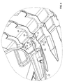
FIG. 7 is a cross-sectional view of the optical fiber management system of FIGS. 1-6 shown being provided on a plurality of trays mounted on a telecommunications fixture, wherein the cross-section is taken along a line similar to line A-A of FIG. 1.
DETAILED DESCRIPTION
Reference will now be made in detail to exemplary aspects of the present disclosure that are illustrated in the accompanying drawings. Wherever possible, the same reference numbers will be used throughout the drawings to refer to the same or like parts.
Optical fiber distribution systems may include equipment such as trays that are mounted in telecommunications fixtures such as telecommunications enclosures (e.g., pull-out drawers, etc.), wherein the trays may house fiber terminations in the form of splices or splitters. Such trays may be provided as pivotable trays that can be flipped for access to the trays.
One concern regarding such flip trays relates to the deflection of certain parts of the trays when the trays are being pivotally moved. For example, according to one example, if a tray is pivotally mounted to the telecommunications enclosures via a hinge structure that is positioned nearer to the center of the tray edge, the ends of the tray edge may experience a certain amount of deflection and bending during the pivotal movement of the tray. Such deflection may eventually result in warping of the trays. If optical fibers of a system are entering or exiting the trays at portions that either undergo deflection or have undergone warping, fiber breakage becomes a concern at those portions due to misalignment of parts and excessive bending of the fibers.
Referring now to FIGS. 1-7 in general, an optical fiber management system 10, having features that are examples of inventive aspects in accordance with the disclosure, is shown. As will be discussed in further detail, the fiber management system 10 is designed to limit deflection of certain parts of flip trays to limit breakage of fibers that are exiting or entering the trays at those portions. The fiber management system 10 is configured to limit those portions of the tray that are guiding fibers in and out of the tray from excessive deflection and warping. In this manner, those portions of the tray that are guiding fibers can stay aligned with other portions of the fixture to which the tray is mounted to provide a smooth fiber path, without the fibers experiencing excessive bending.
Still referring to FIGS. 1-7, in an example optical fiber distribution system 12, a telecommunications fixture in the form of an enclosure 14 may include a plurality of flip trays 16 (one shown) containing fiber optic splices. Splitters can also be provided if desired. The trays 16 are pivotally mounted to the fixture 14 to allow flipping of the trays 16 for access to the interiors of the trays 16.
As shown, each tray 16 is pivotally mounted to the fixture 14 via a hinge structure 18 that is cooperatively formed by the fixture 14 and the tray 16. Portions of the hinge structure 18 that are located on the tray 16 are positioned closer to the center 20 of the tray edge 22. Thus, a tray such as the tray 16 shown in FIGS. 1-7, without the inventive optical fiber management system 10 of the present disclosure, may experience some deflection at the outer ends 24 of the tray edge 22 when the tray 16 is pivotally moved. Since a user may tend to grab the tray 16 at one of its longitudinal ends for the pivotal motion, the tray 16 may experience some torquing or a bending moment that is spaced away from the hinge structure 18. As noted above, if a fiber or a plurality of fibers are entering and exiting the tray 16 at portions that experience the deflection, fiber breakage may eventually become a concern due to misalignment of parts and excessive bending forces on the fibers.
In the optical fiber distribution system 12 of the present disclosure, the telecommunications fixture 14 and each tray 16 cooperatively form the inventive optical fiber management system 10 of the present disclosure. As shown, each tray 16 defines a fiber guide 26 positioned at the outer ends 24 of the tray edge 22. In the depicted embodiment, each fiber guide 26 is generally of a cylindrical configuration with open ends 28 in the form of a split-ring. The fiber guide 26 defines a slit 30 for inserting/removing fibers in a direction transverse to the open ends 28. Each fiber guide 26 is also connected to the main tray body via neck portion 32.
In the given embodiment, each fiber guide 26 is configured to lead fibers to and from a fiber entry/exit area/channel 34 that leads to fiber entry/exit points 36 in the tray 16. The channel 34 is defined by a plurality of fiber management fingers 38 that are configured to retain the fibers within the channel 34. Once the fibers enter the tray 16, the fibers can be lead to different areas for processing (i.e., splicing, splitting, etc.).
The fiber guide 26 is configured to define a longitudinal axis 40 that is generally parallel to a longitudinal/pivotal axis 42 defined by the hinge structure 18. According to the given embodiment, the longitudinal axis 40 of the fiber guide 26 is aligned with that of the hinge structure 18 to minimize the amount of movement for the fibers that are entering or exiting the tray 16.
According to the present disclosure, the fiber guides 26 of the tray 16 form a part of the optical fiber management system 10. The other part of the optical fiber management system 10 is defined by the telecommunications fixture 14. As shown, the telecommunications fixture 14 that houses the flip trays 16 defines a plurality of cable exit or entry channels 44 that are provided in a stacked arrangement. Each fiber guide 26 is configured to guide the fibers of the tray 16 toward the channels 44. A portion of each of the channels defines a reinforcement portion or reinforcement channel 46. The reinforcement channel 46 is defined by a U-shaped wall 48 that is configured to partially envelop the fiber guides 26 of the trays 16 and limit deflection of the fiber guides 26. As shown in the cross-sectional view of FIG. 7, each U-shaped wall 48 defines opposing vertical wall portions 50 that abut the fiber guides 26 and limit movement of the fiber guides 26 within the reinforcement channel 46.
In this manner, when a user decides to pivotally flip one of the trays 16 to an open configuration, the guides 26 stay within the reinforcement channels 46 and the outer ends 24 of the tray edge 22 are limited from deflection so as to limit warping of the trays and eventual fiber breakage. For each of the trays 16, the fixture 14 also defines a stop surface 52 adjacent each outer end 24 of the tray 16. The stop surfaces 52 are configured to contact the neck portions 32 to provide positive stops during the pivotal motion of the trays 16.
Thus, the optical fiber management system 10 of the present disclosure that is cooperatively formed by a combination of portions of the flip trays 16 and portions of the fixtures 14 to which they are mounted limit deflection of the trays 16 and provide secured fiber movement and rotation during pivotal movement of the trays 16.
It should be noted that the depicted embodiments of the flip trays 16 and the telecommunications fixture in the form of the enclosure 14 used to show the inventive aspects of the optical fiber management system 10 of the present disclosure are exemplary embodiments, and the inventive aspects may be employed on other types of trays and fixtures.
The above specification, examples and data provide a complete description of the manufacture and use of the composition of the inventive aspects. Since many embodiments of the disclosure can be made without departing from the spirit and scope of the disclosure, the inventive aspects reside in the claims hereinafter appended.
LIST OF REFERENCE NUMERALS AND CORRESPONDING FEATURES
  • 10 Optical fiber management system
  • 12 Optical fiber distribution system
  • 14 Telecommunications fixture/enclosure
  • 16 Flip tray
  • 18 Hinge structure
  • 20 Center
  • 22 Tray edge
  • 24 Outer end
  • 26 Fiber guide
  • 28 Open end
  • 30 Slit
  • 32 Neck portion
  • 34 Fiber entry/exit area/channel
  • 36 Fiber entry/exit point of tray
  • 38 Fiber management finger
  • 40 Longitudinal axis of fiber guide
  • 42 Longitudinal/pivotal axis of hinge structure
  • 44 Cable exit/entry channel of fixture
  • 46 Reinforcement channel
  • 48 U-shaped wall
  • 50 Vertical wall portion
  • 52 Stop surface

Claims (15)

What is claimed is:
1. An optical fiber management system comprising:
a telecommunications fixture;
a telecommunications tray pivotally mounted to the telecommunications fixture via a hinge structure positioned at an edge of the tray, wherein at least one end of the tray edge that is spaced from the hinge structure defines a fiber guide having a generally cylindrical configuration with open ends for guiding fibers in and/or out of the tray, wherein the fiber guide is nested within a reinforcement channel defined by a generally U-shaped wall of the telecommunications fixture, the U-shaped wall defining opposing vertical wall portions for abutting the fiber guide of the tray for retaining the fiber guide within the reinforcement channel during pivotal movement of the tray.
2. A system according to claim 1, wherein two ends of the tray edge that are spaced from the hinge structure both define a fiber guide, wherein each fiber guide is nested within a reinforcement channel defined by a generally U-shaped wall of the telecommunications fixture.
3. A system according to claim 2, wherein the hinge structure is generally positioned at a center point along the tray edge in between the two fiber guides.
4. A system according to claim 1, wherein the fiber guide defines a longitudinal axis that is generally parallel to a pivotal axis of the hinge structure.
5. A system according to claim 4, wherein the longitudinal axis defined by the fiber guide is generally aligned with the pivotal axis of the hinge structure.
6. A system according to claim 1, wherein both fiber guides define longitudinal axes that are generally parallel to a pivotal axis of the hinge structure.
7. A system according to claim 6, wherein the longitudinal axes defined by the fiber guides are generally aligned with the pivotal axis of the hinge structure.
8. A system according to claim 1, wherein the fiber guide generally defines a split-ring configuration defining a slit for receiving fibers along a direction transverse to the open ends.
9. A system according to claim 1, wherein the telecommunications fixture is configured to house a plurality of the trays.
10. A flip tray for pivotal mounting in a telecommunications fixture, the flip tray configured for housing optical fibers, the tray comprising:
a hinge structure positioned along an edge of the tray for pivotal mounting to the fixture;
a pair of fiber guides positioned at outer ends of the tray edge spaced from the hinge structure, each fiber guide defining a generally cylindrical configuration with open ends for guiding fibers in and/or out of the tray, wherein longitudinal axes defined by the fiber guides are generally parallel to a pivotal axis defined by the hinge structure.
11. A tray according to claim 10, wherein the hinge structure is generally positioned at a center point along the tray edge in between the two fiber guides such that the fiber guides are generally equally spaced from the hinge structure.
12. A tray according to claim 10, wherein the longitudinal axes defined by the fiber guides are generally aligned with the pivotal axis of the hinge structure.
13. A tray according to claim 10, wherein each fiber guide generally defines a split-ring configuration defining a slit for receiving fibers along a direction transverse to the open ends.
14. A tray according to claim 10, wherein the tray is configured to contain fiber optic splices.
15. A tray according to claim 10, wherein the tray defines a neck portion extending from a main body of the tray to each fiber guide, each neck portion configured to cooperatively form a positive stop with a portion of the telecommunications fixture during pivotal movement of the tray.
US15/779,016 2015-11-25 2016-11-24 Fiber management for pivotable trays having fiber guides spaced apart from hinges Active US10310207B2 (en)

Priority Applications (1)

Application Number Priority Date Filing Date Title
US15/779,016 US10310207B2 (en) 2015-11-25 2016-11-24 Fiber management for pivotable trays having fiber guides spaced apart from hinges

Applications Claiming Priority (3)

Application Number Priority Date Filing Date Title
US201562260073P 2015-11-25 2015-11-25
US15/779,016 US10310207B2 (en) 2015-11-25 2016-11-24 Fiber management for pivotable trays having fiber guides spaced apart from hinges
PCT/EP2016/078683 WO2017089463A1 (en) 2015-11-25 2016-11-24 Fiber management for pivotable trays

Related Parent Applications (1)

Application Number Title Priority Date Filing Date
PCT/EP2016/078683 A-371-Of-International WO2017089463A1 (en) 2015-11-25 2016-11-24 Fiber management for pivotable trays

Related Child Applications (2)

Application Number Title Priority Date Filing Date
US16/426,596 Continuation US10895704B2 (en) 2015-11-25 2019-05-30 Fiber management for pivotable trays having fiber guides spaced apart from hinges
US16/426,596 Continuation-In-Part US10895704B2 (en) 2015-11-25 2019-05-30 Fiber management for pivotable trays having fiber guides spaced apart from hinges

Publications (2)

Publication Number Publication Date
US20180348463A1 US20180348463A1 (en) 2018-12-06
US10310207B2 true US10310207B2 (en) 2019-06-04

Family

ID=57394578

Family Applications (4)

Application Number Title Priority Date Filing Date
US15/779,016 Active US10310207B2 (en) 2015-11-25 2016-11-24 Fiber management for pivotable trays having fiber guides spaced apart from hinges
US16/426,596 Active US10895704B2 (en) 2015-11-25 2019-05-30 Fiber management for pivotable trays having fiber guides spaced apart from hinges
US17/149,292 Active US11385430B2 (en) 2015-11-25 2021-01-14 Fiber management for pivotable trays having fiber guides spaced apart from hinges
US17/853,231 Active US11624887B2 (en) 2015-11-25 2022-06-29 Fiber management for pivotable trays having fiber guides spaced apart from hinges

Family Applications After (3)

Application Number Title Priority Date Filing Date
US16/426,596 Active US10895704B2 (en) 2015-11-25 2019-05-30 Fiber management for pivotable trays having fiber guides spaced apart from hinges
US17/149,292 Active US11385430B2 (en) 2015-11-25 2021-01-14 Fiber management for pivotable trays having fiber guides spaced apart from hinges
US17/853,231 Active US11624887B2 (en) 2015-11-25 2022-06-29 Fiber management for pivotable trays having fiber guides spaced apart from hinges

Country Status (5)

Country Link
US (4) US10310207B2 (en)
EP (1) EP3380880B1 (en)
DK (1) DK3380880T3 (en)
ES (1) ES2814330T3 (en)
WO (1) WO2017089463A1 (en)

Cited By (2)

* Cited by examiner, † Cited by third party
Publication number Priority date Publication date Assignee Title
US20190346647A1 (en) * 2015-11-25 2019-11-14 CommScope Connectivity Belgium BVBA Fiber management for pivotable trays having fiber guides spaced apart from hinges
US11275226B2 (en) 2018-04-23 2022-03-15 Commscope Technologies Llc Pivot interlock for a fiber management tray

Families Citing this family (4)

* Cited by examiner, † Cited by third party
Publication number Priority date Publication date Assignee Title
US11635578B2 (en) * 2018-04-17 2023-04-25 CommScope Connectivity Belgium BVBA Telecommunications distribution elements
WO2021148552A1 (en) * 2020-01-24 2021-07-29 CommScope Connectivity Belgium BVBA Telecommunications distribution elements
AU2021367929A1 (en) * 2020-10-30 2023-06-22 Commscope Technologies Llc Space efficient optical fiber tray organizer for a telecommunications closure
EP4330751A1 (en) * 2021-04-30 2024-03-06 CommScope Technologies LLC Optical fiber management trays with increased splice management capacity

Citations (16)

* Cited by examiner, † Cited by third party
Publication number Priority date Publication date Assignee Title
DE9217305U1 (en) 1992-12-18 1993-03-04 General Electric Plastics B.V., Bergen Op Zoom, Nl
WO1994023324A1 (en) 1993-04-01 1994-10-13 N.V. Raychem S.A. Optical fibre organizer
GB2312053A (en) 1996-04-12 1997-10-15 Telephone Cables Ltd Splice cassettes with optic fibre guide on hinge axis
US6009225A (en) * 1998-05-26 1999-12-28 Ray; Craig D. Fiber optic drop splice closure and related methods
FR2793564A1 (en) 1999-05-11 2000-11-17 Rxs Morel Accessoires De Cable STACK OF CASSETTES THAT CAN OPEN FROM TWO SIDES
US20030202765A1 (en) 2002-04-24 2003-10-30 Franklin Michael J. Cable management panel with sliding drawer
WO2004110122A2 (en) 2003-05-30 2004-12-16 Adc Telecommunications, Inc. Optical fiber distribution frame with rotating panel
US20060029351A1 (en) 2002-11-26 2006-02-09 Oliver Lapp Device for the structured storage or handling of optical waveguides
US20100061693A1 (en) 2008-09-09 2010-03-11 Bran De Leon Oscar Fernando Fiber Optic Splice Tray
US7856166B2 (en) * 2008-09-02 2010-12-21 Corning Cable Systems Llc High-density patch-panel assemblies for optical fiber telecommunications
EP2381283A1 (en) 2010-04-22 2011-10-26 Tyco Electronics Raychem BVBA Optical fiber tray assembly
WO2014091371A1 (en) 2012-12-11 2014-06-19 Koninklijke Philips N.V. Enhanced hinge and method for pivotally and removably connecting a member with a structure
WO2014173930A1 (en) 2013-04-24 2014-10-30 Tyco Electronics Raychem Bvba Optical fiber distribution system
ES2544203A2 (en) 2013-05-10 2015-08-27 Tyco Electronics Raychem Bvba System and method for fixing fiber optic tubes in splice trays (Machine-translation by Google Translate, not legally binding)
US20170363831A1 (en) * 2014-11-26 2017-12-21 CommScope Connectivity Belgium BVBA Fiber management tray with two-sided storage pocket
US20180348463A1 (en) * 2015-11-25 2018-12-06 CommScope Connectivity Belgium BVBA Fiber management for pivotable trays having fiber guides spaced apart from hinges

Family Cites Families (15)

* Cited by examiner, † Cited by third party
Publication number Priority date Publication date Assignee Title
US5249252A (en) * 1992-08-31 1993-09-28 Alcatel Network Systems, Inc. Optical fiber splice tray with cable tray hinge
US6427045B1 (en) * 2000-03-08 2002-07-30 Marconi Communications, Inc. Splice tray for use in splicing fiber optic cables and housing therefor
GB0108255D0 (en) * 2001-04-02 2001-05-23 Tyco Electronics Raychem Nv Optical fibre organiser
US7418184B1 (en) * 2007-03-15 2008-08-26 Curtis Paul Gonzales Fiber optic categorization and management tray
US9081164B2 (en) * 2011-08-24 2015-07-14 Adc Telecommunications, Inc. Fiber management panel
US9188760B2 (en) * 2011-12-22 2015-11-17 Adc Telecommunications, Inc. Mini rapid delivery spool
EP2717081B1 (en) * 2012-10-02 2020-11-18 Corning Research & Development Corporation Optical fibre distribution enclosure
AU2016323386B2 (en) * 2015-09-14 2021-04-22 CommScope Connectivity Belgium BVBA Terminal enclosure with modular aspects and modules for interfacing with the terminal enclosure
EP3446554B1 (en) * 2016-04-19 2020-12-02 CommScope, Inc. of North Carolina Telecommunications chassis with slidable trays
WO2017184501A1 (en) * 2016-04-19 2017-10-26 Commscope, Inc. Of North Carolina Door assembly for a telecommunications chassis with a combination hinge structure
WO2018046677A1 (en) * 2016-09-08 2018-03-15 CommScope Connectivity Belgium BVBA Telecommunications distribution elements
US20200033546A1 (en) * 2017-04-04 2020-01-30 CommScope Connectivity Belgium BVBA Optical fiber management tray with over-the-center performance for enhanced opticl fiber accessibility
EP3619565B1 (en) * 2017-05-05 2023-04-26 CommScope Connectivity Belgium BVBA Telecommunications enclosure with modular features
WO2019209813A1 (en) * 2018-04-23 2019-10-31 Commscope Technologies Llc Pivot interlock for a fiber management tray
US10866379B2 (en) * 2018-08-24 2020-12-15 Belden Canada Ulc Flexible cable guide

Patent Citations (16)

* Cited by examiner, † Cited by third party
Publication number Priority date Publication date Assignee Title
DE9217305U1 (en) 1992-12-18 1993-03-04 General Electric Plastics B.V., Bergen Op Zoom, Nl
WO1994023324A1 (en) 1993-04-01 1994-10-13 N.V. Raychem S.A. Optical fibre organizer
GB2312053A (en) 1996-04-12 1997-10-15 Telephone Cables Ltd Splice cassettes with optic fibre guide on hinge axis
US6009225A (en) * 1998-05-26 1999-12-28 Ray; Craig D. Fiber optic drop splice closure and related methods
FR2793564A1 (en) 1999-05-11 2000-11-17 Rxs Morel Accessoires De Cable STACK OF CASSETTES THAT CAN OPEN FROM TWO SIDES
US20030202765A1 (en) 2002-04-24 2003-10-30 Franklin Michael J. Cable management panel with sliding drawer
US20060029351A1 (en) 2002-11-26 2006-02-09 Oliver Lapp Device for the structured storage or handling of optical waveguides
WO2004110122A2 (en) 2003-05-30 2004-12-16 Adc Telecommunications, Inc. Optical fiber distribution frame with rotating panel
US7856166B2 (en) * 2008-09-02 2010-12-21 Corning Cable Systems Llc High-density patch-panel assemblies for optical fiber telecommunications
US20100061693A1 (en) 2008-09-09 2010-03-11 Bran De Leon Oscar Fernando Fiber Optic Splice Tray
EP2381283A1 (en) 2010-04-22 2011-10-26 Tyco Electronics Raychem BVBA Optical fiber tray assembly
WO2014091371A1 (en) 2012-12-11 2014-06-19 Koninklijke Philips N.V. Enhanced hinge and method for pivotally and removably connecting a member with a structure
WO2014173930A1 (en) 2013-04-24 2014-10-30 Tyco Electronics Raychem Bvba Optical fiber distribution system
ES2544203A2 (en) 2013-05-10 2015-08-27 Tyco Electronics Raychem Bvba System and method for fixing fiber optic tubes in splice trays (Machine-translation by Google Translate, not legally binding)
US20170363831A1 (en) * 2014-11-26 2017-12-21 CommScope Connectivity Belgium BVBA Fiber management tray with two-sided storage pocket
US20180348463A1 (en) * 2015-11-25 2018-12-06 CommScope Connectivity Belgium BVBA Fiber management for pivotable trays having fiber guides spaced apart from hinges

Non-Patent Citations (1)

* Cited by examiner, † Cited by third party
Title
International Search Report and Written Opinion of the International Searching Authority for corresponding International Patent Application No. PCT/EP2016/078683 dated Jan. 30, 2017, 9 pages.

Cited By (5)

* Cited by examiner, † Cited by third party
Publication number Priority date Publication date Assignee Title
US20190346647A1 (en) * 2015-11-25 2019-11-14 CommScope Connectivity Belgium BVBA Fiber management for pivotable trays having fiber guides spaced apart from hinges
US10895704B2 (en) * 2015-11-25 2021-01-19 CommScope Connectivity Belgium BVBA Fiber management for pivotable trays having fiber guides spaced apart from hinges
US11385430B2 (en) 2015-11-25 2022-07-12 CommScope Connectivity Belgium BVBA Fiber management for pivotable trays having fiber guides spaced apart from hinges
US11624887B2 (en) 2015-11-25 2023-04-11 CommScope Connectivity Belgium BVBA Fiber management for pivotable trays having fiber guides spaced apart from hinges
US11275226B2 (en) 2018-04-23 2022-03-15 Commscope Technologies Llc Pivot interlock for a fiber management tray

Also Published As

Publication number Publication date
EP3380880A1 (en) 2018-10-03
US10895704B2 (en) 2021-01-19
WO2017089463A1 (en) 2017-06-01
US11624887B2 (en) 2023-04-11
US20180348463A1 (en) 2018-12-06
US20210208354A1 (en) 2021-07-08
US20220326464A1 (en) 2022-10-13
EP3380880B1 (en) 2020-06-24
US20190346647A1 (en) 2019-11-14
ES2814330T3 (en) 2021-03-26
US11385430B2 (en) 2022-07-12
DK3380880T3 (en) 2020-09-07

Similar Documents

Publication Publication Date Title
US11624887B2 (en) Fiber management for pivotable trays having fiber guides spaced apart from hinges
US11320618B2 (en) Optical fiber distribution system
EP1377862B1 (en) Optical fibre organiser
US10509190B2 (en) Multi-positionable telecommunications tray
US11002931B2 (en) Telecommunications tray with a cable routing path extending through a pivot hinge
US6654536B2 (en) Fiber management frame having connector platform
US20160047999A1 (en) Moveable bend control and patch cord support for telecommunications panel
US20090148117A1 (en) Method and device for coupling optical waveguides
US11656413B2 (en) Fiber optic cable slack management module
CN105324697A (en) Optical cable splice cassettes with hingedly attached device holder
US9151920B2 (en) High density optics and electronics enclosure housing system with cable management
US20190064468A1 (en) Termination unit and optical fiber exchange method using the same
US20220196955A1 (en) Optical fiber spice tray organizer
US9383537B2 (en) Cassette and drop handle with flexible radius controller
CA2171347A1 (en) Optical fibre organizer
WO2014122103A1 (en) Fiber tray organizer with fiber bridge
US20230111957A1 (en) Telecommunications distribution elements
US11448840B2 (en) Unitube ribbon breakout
CA2323885A1 (en) Side entry cable guide
US11592637B2 (en) Cable organizer for fiber optic cables
US20220229253A1 (en) Telecommunications cable guide
WO2020205188A1 (en) Fiber optic splice tray
AU2002241148A1 (en) Optical fibre organiser

Legal Events

Date Code Title Description
FEPP Fee payment procedure

Free format text: ENTITY STATUS SET TO UNDISCOUNTED (ORIGINAL EVENT CODE: BIG.); ENTITY STATUS OF PATENT OWNER: LARGE ENTITY

AS Assignment

Owner name: COMMSCOPE CONNECTIVITY BELGIUM BVBA, BELGIUM

Free format text: ASSIGNMENT OF ASSIGNORS INTEREST;ASSIGNORS:GEENS, JOHAN;ALAERTS, ROGER;VERMEULEN, PIETER;AND OTHERS;SIGNING DATES FROM 20181009 TO 20181010;REEL/FRAME:047307/0157

STPP Information on status: patent application and granting procedure in general

Free format text: NOTICE OF ALLOWANCE MAILED -- APPLICATION RECEIVED IN OFFICE OF PUBLICATIONS

STCF Information on status: patent grant

Free format text: PATENTED CASE

MAFP Maintenance fee payment

Free format text: PAYMENT OF MAINTENANCE FEE, 4TH YEAR, LARGE ENTITY (ORIGINAL EVENT CODE: M1551); ENTITY STATUS OF PATENT OWNER: LARGE ENTITY

Year of fee payment: 4