US10303485B2 - Control method for controlling a server system by means of a set of reset signals and a set of notification signals - Google Patents
Control method for controlling a server system by means of a set of reset signals and a set of notification signals Download PDFInfo
- Publication number
- US10303485B2 US10303485B2 US15/466,874 US201715466874A US10303485B2 US 10303485 B2 US10303485 B2 US 10303485B2 US 201715466874 A US201715466874 A US 201715466874A US 10303485 B2 US10303485 B2 US 10303485B2
- Authority
- US
- United States
- Prior art keywords
- server
- notification signal
- signal
- sending
- system boot
- Prior art date
- Legal status (The legal status is an assumption and is not a legal conclusion. Google has not performed a legal analysis and makes no representation as to the accuracy of the status listed.)
- Active, expires
Links
Images


Classifications
-
- G—PHYSICS
- G06—COMPUTING OR CALCULATING; COUNTING
- G06F—ELECTRIC DIGITAL DATA PROCESSING
- G06F11/00—Error detection; Error correction; Monitoring
- G06F11/07—Responding to the occurrence of a fault, e.g. fault tolerance
- G06F11/0703—Error or fault processing not based on redundancy, i.e. by taking additional measures to deal with the error or fault not making use of redundancy in operation, in hardware, or in data representation
- G06F11/0706—Error or fault processing not based on redundancy, i.e. by taking additional measures to deal with the error or fault not making use of redundancy in operation, in hardware, or in data representation the processing taking place on a specific hardware platform or in a specific software environment
- G06F11/0709—Error or fault processing not based on redundancy, i.e. by taking additional measures to deal with the error or fault not making use of redundancy in operation, in hardware, or in data representation the processing taking place on a specific hardware platform or in a specific software environment in a distributed system consisting of a plurality of standalone computer nodes, e.g. clusters, client-server systems
-
- G—PHYSICS
- G06—COMPUTING OR CALCULATING; COUNTING
- G06F—ELECTRIC DIGITAL DATA PROCESSING
- G06F9/00—Arrangements for program control, e.g. control units
- G06F9/06—Arrangements for program control, e.g. control units using stored programs, i.e. using an internal store of processing equipment to receive or retain programs
- G06F9/44—Arrangements for executing specific programs
- G06F9/4401—Bootstrapping
-
- G—PHYSICS
- G06—COMPUTING OR CALCULATING; COUNTING
- G06F—ELECTRIC DIGITAL DATA PROCESSING
- G06F11/00—Error detection; Error correction; Monitoring
- G06F11/07—Responding to the occurrence of a fault, e.g. fault tolerance
- G06F11/0703—Error or fault processing not based on redundancy, i.e. by taking additional measures to deal with the error or fault not making use of redundancy in operation, in hardware, or in data representation
- G06F11/0793—Remedial or corrective actions
-
- G—PHYSICS
- G06—COMPUTING OR CALCULATING; COUNTING
- G06F—ELECTRIC DIGITAL DATA PROCESSING
- G06F9/00—Arrangements for program control, e.g. control units
- G06F9/06—Arrangements for program control, e.g. control units using stored programs, i.e. using an internal store of processing equipment to receive or retain programs
- G06F9/46—Multiprogramming arrangements
- G06F9/54—Interprogram communication
- G06F9/542—Event management; Broadcasting; Multicasting; Notifications
Definitions
- the invention relates to a control method for controlling a server system, and more particularly, a control method for controlling a server system using a set of reset signals and a set of notification signals.
- FIG. 1 illustrates a server system 100 having a chain structure according to prior art.
- a host server 110 may be linked to external servers 120 a - 120 d.
- the external servers 120 a - 120 d are connected sequentially in a series to form a chain structure.
- the host server 110 may send reset signals Sa-Sd delivered stage by stage via interface cards of the external servers 120 a - 120 d so that the external servers 120 a - 120 d may enter an operation mode from a stand-by mode stage by stage. For example, functional units of the external servers may be activated stage by stage. Because the reset signals Sa-Sd may be sent stage by stage in a series, a last stage of the external servers (e.g. the server 120 d )may receive the foresaid reset signal (e.g. Sd) last. Hence, it is possible that a detection time of the host server 110 has ended, but the external server 120 d (i.e. a last stage of server) still has not received the reset signal Sd yet so that the functional units of the server 120 d are still deactivated. The host server 110 may fail to connect to the external servers normally.
- the reason may be the failure of sending a reset signal.
- the external server may fail to be booted, and the host server may hence fail to boot the server system.
- An embodiment of the present invention discloses a control method for controlling a server system.
- the control method may include a host server sending a first reset signal to a first server.
- An i th server may send an (i+1) th reset signal to an (i+1) th server after the i th server receives an i th reset signal from an (i ⁇ 1) th server.
- a system boot operation of an n th server may be performed after the n th server receives an n th reset signal.
- the n th server sends a first notification signal to an (n ⁇ 1) th server after performing the system boot operation of the n th server.
- a system boot operation of an (n ⁇ k) th server may be performed after the (n ⁇ k) th server receives a k th notification signal from an (n ⁇ k+1) th server.
- the (n ⁇ k) th server may send a (k+1) th notification signal to an (n ⁇ k ⁇ 1) th server after performing the system boot operation of the (n ⁇ k) th server.
- a system boot operation of the first server may be performed after the first server receives an (n ⁇ 1) th notification signal from a second server.
- the first server may send an n th notification signal to the host server after performing the system boot operation of the first server.
- FIG. 1 illustrates a server system having a chain structure according to prior art.
- FIGS. 2-3 illustrate a server system according to an embodiment of the present invention.
- FIG. 4 illustrates a flow chart of a control method for controlling the server system of FIGS. 2-3 according to an embodiment of the present invention.
- FIGS. 5-6 illustrates a server system according to another embodiment of the present invention.
- FIG. 7 illustrates extra steps that may be further included by the method of FIG. 4 .
- FIG. 8 illustrates an example of setting the variable n of the server system in FIGS. 5-6 as 5.
- FIGS. 2-3 illustrate a server system 200 according to an embodiment of the present invention. Two figures are used here for explaining the control method described below easier.
- the server system 200 may include a host server 210 and n external servers 2201 - 220 n.
- the server system 200 may be of a chain structure having a set of servers linked in a series.
- the reference numbers of the servers in FIGS. 1-2 may correspond to positions of the servers.
- the server 2201 may be a first server linked to the host server 210 . That is to say, the server 2201 is a closest external server to the host server 210 than other external servers.
- the server 2202 may be a second external server of the external servers, and so on.
- FIG. 4 illustrates a flow chart of a control method 400 for controlling the server system 200 according to an embodiment of the present invention.
- the control method 400 may include:
- Step 402 the host server 210 may send a first reset signal R 1 to the first server 2201 ;
- Step 404 an i th server 220 i may send an (i+1) th reset signal R(i+1) to an (i+1) th server 220 (i+1) after the i th server 220 i receives an i th reset signal Ri from an (i ⁇ 1) th server 220 (i ⁇ 1);
- Step 406 perform a system boot operation of an n th server 220 n after the n th server 220 n receives an n th reset signal Rn;
- Step 408 the n th server 220 n may send a first notification signal A 1 to an (n ⁇ 1) th server 220 (n ⁇ 1) after performing the system boot operation of the n th server 220 n;
- Step 410 perform a system boot operation of an (n ⁇ k) th server 220 (n ⁇ k) after the (n ⁇ k) th server 220 (n ⁇ k) receives a k th notification signal Ak from an (n ⁇ k+1) th server 220 (n ⁇ k+1);
- Step 412 the (n ⁇ k) th server 220 (n ⁇ k) may send a (k+1) th notification signal A(k+1) to an (n ⁇ k ⁇ 1) th server 220 (n ⁇ k ⁇ 1) after performing the system boot operation of the (n ⁇ k) th server 220 (n ⁇ k);
- Step 414 perform a system boot operation of the first server 2201 after the first server 2201 receives an (n ⁇ 1) th notification signal A(n ⁇ 1) from a second server 2202 ;
- Step 416 the first server 2201 may send an n th notification signal An to the host server 210 after performing the system boot operation of the first server 2201 ;
- Step 418 determine whether the host server 210 receives the n th notification signal An during a predetermined time interval; if so, enter Step 422 ; else, enter Step 420 ;
- Step 420 the host server 210 may send the first reset signal R 1 to the first server 2201 again;
- Step 422 the host server 210 may control the servers 2201 - 220 n.
- Step 404 may correspond to the servers 2202 - 220 (n ⁇ 1) sending the reset signals R 3 -Rn.
- Steps 410 - 412 may correspond to the servers 220 (n ⁇ 1) to 2202 sending the notification signals A 2 to A(n ⁇ 1).
- Steps 402 - 406 may correspond to FIG. 2 .
- Steps 408 - 416 may correspond to FIG. 3 .
- Step 404 by substituting the parameter i, it may be described that the server 2201 sends the second reset signal R 2 to the server 2202 , the server 2202 sends the third reset signal R 3 to the server 2203 , and so on till the server 220 (n ⁇ 1) sends the n th reset signal Rn to the server 220 n.
- the server 220 i may send the (i+1) th reset signal R(i+1) to the server 220 (i+1) correspondingly after receiving the i th reset signal Ri.
- Step 406 since the server 220 n may be a last stage of the chain structure, the system boot operation of the server 220 n may be performed after receiving the n th reset signal Rn.
- each of the servers 220 n to 2202 may be described to receive a notification signal from a following server, perform a system boot operation and send another notification signal to a previous server after performing the system boot operation.
- the server 2205 may send a notification signal A(n ⁇ 4) to the server 2204 to inform the server 2204 to perform a system boot operation of the server 2204 .
- the variable of the notification signal A(n ⁇ 4) may be obtained according to a calculation shown in Step 412 .
- the variable (n ⁇ 4) may substitute for the variable (n ⁇ k) in this example.
- the server may inform a previous server closer to the host server to perform a system boot operation, and so on.
- the server 2201 may send the notification signal An to the host server 210 .
- Step 418 if the host server 210 receives the notification signal An during a predetermined time interval, the host server 210 may confirm that the external servers 2201 - 220 n have finished performing the system boot operations, and Step 422 may be performed for the host server 210 to control the servers 2201 - 220 n so that the server system 200 may be under control.
- the host server 210 may perform a system boot operation, and control the statuses of the system boot operations of the servers 2201 - 220 n such as controlling the release of the reset pins of the servers 2201 - 220 n, and the statuses of the PCIe (peripheral component interconnect express) cards of the servers 2201 - 220 n.
- the host server 210 may determine that at least one of the servers 2201 - 220 n fails to perform the system boot operation, and activate the servers 2201 - 220 n to perform the system boot operations again according to Steps 420 , 404 and the following steps.
- a timer may begin to count time in Step 402 .
- the predetermined time interval maybe set longer so as to better confirm that at least one of the servers 2201 - 220 n fails to perform the system boot operation.
- the foresaid timer may be a watch-dog timer or another appropriate sort of timer.
- the foresaid system boot operation of a server may include setting a level of a reset pin of the server from an enabled level to a disabled level such as from 1 to 0 (or from 0 to 1) so that the server may enter an operation mode from a stand-by mode.
- This setting may be called as reset release or reset de-assertion.
- the stand-by mode may correspond to that a control unit of the server keeps operation using a stand-by power, but functional units of the server may be annulled.
- the operation mode may correspond to that the control unit and the functional units of the server are supplied by a functional power, and at least one of the functional units may be activated to be accessed and operated normally.
- the foresaid control unit of the server may be (but not limited to) a complex programmable logic device (CPLD).
- the foresaid functional units may include (but not limited to) a peripheral component interconnect express (PCIe) unit, a platform controller hub (PCH) unit and/or a central processing unit (CPU).
- PCIe peripheral component interconnect express
- PCH platform controller hub
- CPU central processing unit
- Step 408 may be performed by the n th server 220 n sending the first notification signal A 1 to the (n ⁇ 1) th server 220 (n ⁇ 1) after a predetermined time interval corresponding to the server 220 n (which may be seen as an n th predetermined time interval) has elapsed since the n th server 220 n has received the n th reset signal Rn.
- the n th predetermined time interval may be equal to or longer than an expected time interval for the server 220 n to perform the system boot operation. Hence, it may be assured that the server 220 n has completed the system boot operation when the server 220 (n ⁇ 1) receives the notification signal A 1 .
- the server 220 n may send the first notification signal A 1 to the server 220 (n ⁇ 1) after the foresaid predetermined time interval has elapsed since the server 220 n receives the n th reset signal Rn and the system boot operation (e.g. booting all functional units and generating checking signals using a digital circuit) of the server 220 n is performed and confirmed. This may better assure that the server 220 n has completed the system boot operation.
- the system boot operation e.g. booting all functional units and generating checking signals using a digital circuit
- the (n ⁇ k) th server 220 (n ⁇ k) may send the (k+1) th notification signal A(k+1) after an predetermined time interval corresponding to the server 220 (n ⁇ k) (which may be seen as an (n ⁇ k) th predetermined time interval) has elapsed since the server 220 (n ⁇ k) receives the k th notification signal Ak. This is for assuring that the server 220 (n ⁇ k) has completed the system boot operation when the server 220 (n ⁇ k ⁇ 1) receives the notification signal A(k+1).
- Step 412 may include the (n ⁇ k) th server 220 (n ⁇ k) sending the (k+1) th notification signal A(k+1) after the (n ⁇ k) th predetermined time interval has elapsed since the server 220 (n ⁇ k) receives the k th notification signal Ak, and the system boot operation of the server 220 (n ⁇ k) is confirmed to be performed.
- the system boot operation may be confirmed using checking signals. This may further assure that the system boot operation of the server 220 (n ⁇ k) is performed.
- the said server 220 (n ⁇ k) may be each of the servers 2202 - 220 (n ⁇ 1) shown in FIGS. 2-3 .
- Step 416 the server 2201 may send the n th notification signal An to the host server 210 after a first time interval corresponding to the server 2201 has elapsed since the server 2201 receives the (n ⁇ 1) th notification signal A(n ⁇ 1).
- Step 416 may include the server 2201 sending the n th notification signal An after the first time interval has elapsed since the server 2201 receives the (n ⁇ 1) th notification signal A(n ⁇ 1) and the system boot operation of the server 2201 has been confirmed to be performed.
- the system boot operation of the server 2201 may be confirmed by generating and using a checking signal, or using other confirmation means practicable on an electric circuit.
- the foresaid n th predetermined time interval, the (n ⁇ k) th predetermined time interval and the n th time interval may be measured by counting time using watch-dog timers set in the servers.
- FIGS. 5-6 illustrate the server system 200 according to another embodiment of the present invention.
- FIGS. 5-6 may be read with reference to FIG. 7 .
- FIG. 7 illustrates extra steps that may be further included by the method 400 according to another embodiment of the present invention.
- the method 400 may further include:
- Step 710 the host server 210 may send a first stage calculation signal S 1 to the first server 2201 ;
- Step 712 the i th server 220 i may send an (i+1) th stage calculation signal S(i+1) to the (i+1) th server 220 (i+1) after the i th server 220 i receives an i th stage calculation signal Si from the (i ⁇ 1) th server 220 (i ⁇ 1);
- Step 714 the n th server 220 n may send a first stage reply signal C 1 to the (n ⁇ 1) th server 220 (n ⁇ 1) after the n th server 220 n receives an n th stage calculation signal Sn from the (n ⁇ 1) th server 220 (n ⁇ 1);
- Step 716 the (n ⁇ k) th server 220 (n ⁇ k) may send a (k+1) th stage reply signal C(k+1) to the (n ⁇ k ⁇ 1) th server 220 (n ⁇ k ⁇ 1) after the (n ⁇ k) th server 220 (n ⁇ k) receives a k th stage reply signal Ck from the (n ⁇ k+1) th server 220 (n ⁇ k+1);
- Step 718 the first server 2201 may send an n th stage reply signal Cn to the host server 210 after the first server 2201 receives an (n ⁇ 1) th stage reply signal C(n ⁇ 1) from the second server 2202 ;
- Step 720 the (n ⁇ k) th server 220 (n ⁇ k) may generate an expected time T(n ⁇ k) for the (n ⁇ k) th server 220 (n ⁇ k) to receive the k th notification signal Ak according to the k th stage reply signal Ck;
- Step 722 the first server 2201 may generate an expected time T 1 for the first server 2201 to receive the (n ⁇ 1) th notification signal A(n ⁇ 1) according to the (n ⁇ 1) th stage reply signal C(n ⁇ 1);
- Step 724 the host server 210 may generate an expected time Th for the host server 210 to receive the n th notification signal An according to the n th stage reply signal Cn;
- Step 726 determine whether the host server 210 receives the notification signal An at the expected time Th for the host server 210 to receive the notification signal An; if so, enter Step 422 ; else, enter Step 402 .
- Steps 710 - 712 may be read by referring to FIG. 5 .
- Steps 714 - 726 may be read by referring to FIG. 6 .
- the relationships of the variables may be 1 ⁇ i ⁇ n, and 0 ⁇ k ⁇ (n ⁇ 1), and the variables i, k and n may be positive integers. Therefore, the server 220 (n ⁇ k) in Step 720 may correspond to each of the servers 2202 - 220 (n ⁇ 1) in FIGS. 6-7 .
- Step 710 may be performed before or after Step 402 .
- Another path (such as a path via another data bus or other input/output ports) different from the path for sending the first reset signal R 1 , may be used to send the stage calculation signal S 1 so that Steps 710 and 402 may be performed concurrently.
- Steps 710 - 726 may be performed so that each server may know what stage number corresponding to the server itself in the chain structure of the server system.
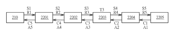
- FIG. 8 illustrates an example of setting the variable n of the server system 200 in FIGS. 5-6 as 5.
- FIG. 8 may be used for an easier explanation.
- the host server 210 may linked to the five servers 2201 - 2205 externally.
- the stage calculation signals S 1 -S 5 may be sent to the servers 2201 - 2205 respectively and sequentially, and the stage reply signals C 1 -C 5 may be sent back from the servers 2205 - 2201 stage by stage so that the host server 210 may receive the stage reply signal C 5 .
- each stage reply signal may be a set of codes, and a header of each stage reply signal may be added by one stage by stage.
- a control unit e.g. a complex programmable logic device, also known as CPLD
- the control unit of the server 2203 may estimate a reasonable time interval for the server 2203 to receive the notification signal A 2 .
- the reasonable time interval may be calculated by referring to a time point of sending the reset signal R 4 , the expected time intervals for the servers 2204 - 2205 to perform system boot operations, and a reasonable time margin.
- Time T 3 expected for the server 2203 to receive the notification signal A 2 may be obtained.
- Time T 3 may be (but not limited to) an expected time point.
- the server 220 (n ⁇ k) may perform the system boot operation of the server 220 (n ⁇ k) if the server 220 (n ⁇ k) fails to receive the k th notification signal Ak at the expected time for the server 220 (n ⁇ k) to receive the signal Ak (which may be represented as a time T(n ⁇ k)).
- the server 2203 fails to receive the notification signal A 2 at time T 3 , it may be determined that the system boot operation(s) of the server 2204 and/or the server 2205 may fail.
- the server 2203 fails to receive the notification signal A 2
- the server 2203 may still perform the system boot operation and send the notification signal A 3 to the server 2202 after performing the system boot operation.
- the notification signal A 5 may be sent to the host server 210 successfully so that the host server 210 may confirm that the external servers 2201 - 2203 have performed the system boot operations successfully.
- the host server 210 may merely use the servers 2201 - 2203 for the following tasks. The said following tasks may include performing a platform reset to perform a boot procedure of the server system, and other following data calculations.
- other servers such as the servers 2204 - 2205 ) linked after the server 2203 may be not used.
- the host server may assure that each server of the external server chain has performed a corresponding system boot operation (e.g. a warm boot operation) normally. Hence, it may be avoided that some functional units of a server are not activated when booting the server system or performing other control operation.
- the control method provided by embodiments of the present invention may be feasible for a server system having a structure of a daisy chain or another similar structure, and is helpful for preventing the problems of the prior art and reducing the failure rate for the host server to control the server system.
Landscapes
- Engineering & Computer Science (AREA)
- Theoretical Computer Science (AREA)
- Software Systems (AREA)
- General Engineering & Computer Science (AREA)
- Physics & Mathematics (AREA)
- General Physics & Mathematics (AREA)
- Computer Security & Cryptography (AREA)
- Multimedia (AREA)
- Quality & Reliability (AREA)
- Computer Hardware Design (AREA)
- Hardware Redundancy (AREA)
- Numerical Control (AREA)
- Computer Networks & Wireless Communication (AREA)
- Signal Processing (AREA)
Abstract
Description
Claims (10)
Applications Claiming Priority (3)
| Application Number | Priority Date | Filing Date | Title |
|---|---|---|---|
| CN201611019810 | 2016-11-17 | ||
| CN201611019810.7A CN108073463A (en) | 2016-11-17 | 2016-11-17 | The control method of server system |
| CN201611019810.7 | 2016-11-17 |
Publications (2)
| Publication Number | Publication Date |
|---|---|
| US20180139304A1 US20180139304A1 (en) | 2018-05-17 |
| US10303485B2 true US10303485B2 (en) | 2019-05-28 |
Family
ID=62108896
Family Applications (1)
| Application Number | Title | Priority Date | Filing Date |
|---|---|---|---|
| US15/466,874 Active 2037-12-26 US10303485B2 (en) | 2016-11-17 | 2017-03-23 | Control method for controlling a server system by means of a set of reset signals and a set of notification signals |
Country Status (2)
| Country | Link |
|---|---|
| US (1) | US10303485B2 (en) |
| CN (1) | CN108073463A (en) |
Family Cites Families (4)
| Publication number | Priority date | Publication date | Assignee | Title |
|---|---|---|---|---|
| US7003563B2 (en) * | 2001-11-02 | 2006-02-21 | Hewlett-Packard Development Company, L.P. | Remote management system for multiple servers |
| CN101847135B (en) * | 2009-03-26 | 2014-06-18 | 杭州士兰微电子股份有限公司 | Series-connected communication system and communication method thereof |
| CN103454996B (en) * | 2013-08-23 | 2016-01-27 | 广州视睿电子科技有限公司 | Master-slave system and control method thereof |
| CN103744811A (en) * | 2013-12-27 | 2014-04-23 | 华中科技大学 | Serial data transmission system and method |
-
2016
- 2016-11-17 CN CN201611019810.7A patent/CN108073463A/en active Pending
-
2017
- 2017-03-23 US US15/466,874 patent/US10303485B2/en active Active
Also Published As
| Publication number | Publication date |
|---|---|
| US20180139304A1 (en) | 2018-05-17 |
| CN108073463A (en) | 2018-05-25 |
Similar Documents
| Publication | Publication Date | Title |
|---|---|---|
| US9716612B2 (en) | Evaluation of field replaceable unit dependencies and connections | |
| CN112015599B (en) | Method and apparatus for error recovery | |
| JPH0651802A (en) | Programmable controller having backup function | |
| CN106610712B (en) | Substrate management controller resetting system and method | |
| CN107070731B (en) | Master-slave arbitration method and system | |
| RU2614569C2 (en) | Rack with automatic recovery function and method of automatic recovery for this rack | |
| TWI576706B (en) | Method for early boot phase and the related device | |
| US20120131384A1 (en) | Computer system | |
| CN114968629A (en) | Computer system and dedicated crash dump device and method for recording error data | |
| US20140143597A1 (en) | Computer system and operating method thereof | |
| US10691562B2 (en) | Management node failover for high reliability systems | |
| CN105912414A (en) | Method and system for server management | |
| US10303485B2 (en) | Control method for controlling a server system by means of a set of reset signals and a set of notification signals | |
| US20130091380A1 (en) | Dynamically Reconfiguring A Primary Processor Identity Within A Multi-Processor Socket Server | |
| CN115617550A (en) | Processing device, control unit, electronic device, method, and computer program | |
| CN106446311B (en) | CPU alarm circuit and alarm method | |
| US20180145869A1 (en) | Debugging method of switches | |
| CN109726055B (en) | Method for detecting PCIe chip abnormity and computer equipment | |
| US9639438B2 (en) | Methods and systems of managing an interconnection | |
| US11989567B2 (en) | Automatic systems devices rediscovery | |
| CN110069272A (en) | The method and electronic equipment of logical file upgrading | |
| CN109542522A (en) | A kind of FPGA starting method and device | |
| CN116541211A (en) | Keyboard controller style interface fault redundancy method and device | |
| CN114443446A (en) | Hard disk indicator lamp control method, system, terminal and storage medium | |
| US10831686B1 (en) | Method of determining hard disk operation status |
Legal Events
| Date | Code | Title | Description |
|---|---|---|---|
| AS | Assignment |
Owner name: INVENTEC CORPORATION, TAIWAN Free format text: ASSIGNMENT OF ASSIGNORS INTEREST;ASSIGNOR:CHEN, CHIA-HSIANG;REEL/FRAME:041689/0813 Effective date: 20170316 Owner name: INVENTEC (PUDONG) TECHNOLOGY CORP., CHINA Free format text: ASSIGNMENT OF ASSIGNORS INTEREST;ASSIGNOR:CHEN, CHIA-HSIANG;REEL/FRAME:041689/0813 Effective date: 20170316 |
|
| STPP | Information on status: patent application and granting procedure in general |
Free format text: NOTICE OF ALLOWANCE MAILED -- APPLICATION RECEIVED IN OFFICE OF PUBLICATIONS |
|
| STPP | Information on status: patent application and granting procedure in general |
Free format text: PUBLICATIONS -- ISSUE FEE PAYMENT VERIFIED |
|
| STCF | Information on status: patent grant |
Free format text: PATENTED CASE |
|
| MAFP | Maintenance fee payment |
Free format text: PAYMENT OF MAINTENANCE FEE, 4TH YEAR, LARGE ENTITY (ORIGINAL EVENT CODE: M1551); ENTITY STATUS OF PATENT OWNER: LARGE ENTITY Year of fee payment: 4 |