US10294697B2 - Access-control system for door lock - Google Patents
Access-control system for door lock Download PDFInfo
- Publication number
- US10294697B2 US10294697B2 US15/040,512 US201615040512A US10294697B2 US 10294697 B2 US10294697 B2 US 10294697B2 US 201615040512 A US201615040512 A US 201615040512A US 10294697 B2 US10294697 B2 US 10294697B2
- Authority
- US
- United States
- Prior art keywords
- lock
- doorknob
- actuator
- operative
- cover
- Prior art date
- Legal status (The legal status is an assumption and is not a legal conclusion. Google has not performed a legal analysis and makes no representation as to the accuracy of the status listed.)
- Active, expires
Links
Images


Classifications
-
- E—FIXED CONSTRUCTIONS
- E05—LOCKS; KEYS; WINDOW OR DOOR FITTINGS; SAFES
- E05B—LOCKS; ACCESSORIES THEREFOR; HANDCUFFS
- E05B63/00—Locks or fastenings with special structural characteristics
- E05B63/0043—Dummy or simulated locks; Cover elements without lock function
-
- E—FIXED CONSTRUCTIONS
- E05—LOCKS; KEYS; WINDOW OR DOOR FITTINGS; SAFES
- E05B—LOCKS; ACCESSORIES THEREFOR; HANDCUFFS
- E05B1/00—Knobs or handles for wings; Knobs, handles, or press buttons for locks or latches on wings
- E05B1/0007—Knobs
-
- E—FIXED CONSTRUCTIONS
- E05—LOCKS; KEYS; WINDOW OR DOOR FITTINGS; SAFES
- E05B—LOCKS; ACCESSORIES THEREFOR; HANDCUFFS
- E05B37/00—Permutation or combination locks; Puzzle locks
- E05B37/20—Puzzle locks, e.g. of labyrinth type; Fasteners with hidden or secret actuating mechanisms
-
- E—FIXED CONSTRUCTIONS
- E05—LOCKS; KEYS; WINDOW OR DOOR FITTINGS; SAFES
- E05B—LOCKS; ACCESSORIES THEREFOR; HANDCUFFS
- E05B67/00—Padlocks; Details thereof
- E05B67/003—Chain, wire or cable locks
-
- E—FIXED CONSTRUCTIONS
- E05—LOCKS; KEYS; WINDOW OR DOOR FITTINGS; SAFES
- E05B—LOCKS; ACCESSORIES THEREFOR; HANDCUFFS
- E05B67/00—Padlocks; Details thereof
- E05B67/06—Shackles; Arrangement of the shackle
- E05B67/22—Padlocks with sliding shackles, with or without rotary or pivotal movement
-
- E—FIXED CONSTRUCTIONS
- E05—LOCKS; KEYS; WINDOW OR DOOR FITTINGS; SAFES
- E05C—BOLTS OR FASTENING DEVICES FOR WINGS, SPECIALLY FOR DOORS OR WINDOWS
- E05C19/00—Other devices specially designed for securing wings, e.g. with suction cups
- E05C19/18—Portable devices specially adapted for securing wings
-
- E—FIXED CONSTRUCTIONS
- E05—LOCKS; KEYS; WINDOW OR DOOR FITTINGS; SAFES
- E05C—BOLTS OR FASTENING DEVICES FOR WINGS, SPECIALLY FOR DOORS OR WINDOWS
- E05C7/00—Fastening devices specially adapted for two wings
-
- E—FIXED CONSTRUCTIONS
- E05—LOCKS; KEYS; WINDOW OR DOOR FITTINGS; SAFES
- E05B—LOCKS; ACCESSORIES THEREFOR; HANDCUFFS
- E05B1/00—Knobs or handles for wings; Knobs, handles, or press buttons for locks or latches on wings
- E05B1/0015—Knobs or handles which do not operate the bolt or lock, e.g. non-movable; Mounting thereof
-
- E—FIXED CONSTRUCTIONS
- E05—LOCKS; KEYS; WINDOW OR DOOR FITTINGS; SAFES
- E05B—LOCKS; ACCESSORIES THEREFOR; HANDCUFFS
- E05B53/00—Operation or control of locks by mechanical transmissions, e.g. from a distance
- E05B53/003—Operation or control of locks by mechanical transmissions, e.g. from a distance flexible
Definitions
- the present disclosure relates to doorknobs, and in particular, to an access-control system for a doorknob. More particularly, the present disclosure relates to a security system that can be mounted on a doorknob and operated to enable or disable functional operation of the doorknob.
- a doorknob security system includes a doorknob cover that is adapted to be coupled to a doorknob that is associated with a door for movement relative to the doorknob.
- the doorknob security system further includes a non-operative movable DECOY lock-actuator button that is supported in a visible position adjacent to the doorknob cover for movement relative to the doorknob cover between a normal projected position and a temporary depressed position without activating an operative lock actuator that is linked to a door lock.
- the door lock is associated with the doorknob and cannot be unlocked regardless of how many times an unauthorized child or other unknowing child pushes the non-operative movable DECOY lock-actuator button.
- the doorknob is supported on a knob-support spindle for rotation about an axis to control movement of a movable door latch relative to a door from (1) an extended position arranged to project into a latch receptacle formed in a companion door frame so that movement of the door relative to the companion door frame is blocked to retain the door in a closed position to (2) a retracted position withdrawn from the latch receptacle so that the door is free to be moved relative to the door frame to an opened position.
- the door latch does not move relative to the door from the extended position to the retracted position when the movable DECOY lock-actuator button is pushed.
- the movable door latch cooperates with a latch-motion blocker to provide a door lock that is associated with the door but is not connected to the non-operative movable DECOY lock-actuator button.
- the latch-motion blocker is coupled to an operative lock actuator that is coupled to the rotatable doorknob and is separated from the non-operative movable DECOY lock-actuator button.
- the operative lock actuator is normally hidden from view in accordance with the present disclosure so the only actuator-like component that is seen by an observer is a non-operative movable DECOY lock-actuator button that has the appearance of being real but, in fact, is non-functional and cannot be operated to lock or unlock the door lock.
- the doorknob security system is mounted on a doorknob in accordance with the present disclosure to conceal the operative lock actuator and provide a non-operative visible and movable DECOY look-actuator button that will be seen by children.
- the DECOY lock-actuator button can be moved relative to a companion doorknob cover when pushed to provide the illusion of a functional lock actuator.
- the DECOY lock-actuator button is not connected to a door lock associated with the doorknob and therefore cannot be operated to unlock the door lock.
- a doorknob security system comprises an actuator access-control shield that is mounted on a doorknob cover in accordance with the present disclosure to cover an aperture formed in a top wall of the doorknob cover to conceal an operative lock actuator located in an interior region bounded by the doorknob cover.
- the actuator access-control shield includes a non-operative movable DECOY lock-actuator button that lies in a prominent position above the doorknob cover so that is visible and will be seen by any children that try unlock a locked doorknob.
- the DECOY lock-actuator button is mounted for movement on a movable button support that is also included in the actuator access-control shield and is normally mounted for movement on the doorknob cover between an actuator-hiding position and an actuator-accessing position. Unknowing children can see and push the non-operative movable DECOY lock-actuator button included in the actuator access-control shield repeatedly without moving the hidden operative lock actuator that must be operated to unlock the door lock.
- knowing caregivers can move the movable button support of the actuator access-control shield away from the doorknob cover from the actuator-hiding position to the actuator-accessing position to separate the DECOY lock-actuator button from the doorknob cover and open a lock actuator access aperture formed in the doorknob cover so as to expose the operative lock actuator that is coupled to the doorknob.
- the operative lock actuator can be gripped, touched, or otherwise activated by a person reaching through the now-opened lock actuator access aperture and then operated relative to the doorknob to unlock the door lock.
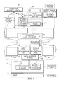
- FIG. 1 is a diagrammatic view of a doorknob security system in accordance with the present disclosure that is adapted to be mounted on a doorknob that is associated with (1) a door, (2) a door lock, and (3) an operative lock actuator associated with the doorknob and door lock, and suggesting that the doorknob security system includes a relatively rigid doorknob cover formed to include a lock actuator access opening, a movable button support mounted for selective movement relative to the doorknob cover between an aperture-closing position suggested in FIG. 1 and an aperture-opening position suggested in FIG.
- a DECOY lock-actuator button mounted in a visible position for movement on the movable button support and arranged to cooperate with the movable button support to define an actuator access-control shield
- a knob rotation system comprising deformable elastic first and second force-transmission pads coupled to the relatively rigid doorknob cover to cover pad-receiver apertures formed in a side wall of the doorknob cover and further suggesting that the door lock includes (1) a movable latch that can be extended and retracted relative to the door in response to rotation of the rotatable doorknob and a knob-support spindle coupled to the rotatable doorknob and a (2) latch-motion blocker that is included in the door lock and can be actuated as suggested in FIG.
- FIG. 2 is a view similar to FIG. 1 showing that an unknowing child has pushed downwardly on the visible DECOY lock-actuator button to move that button relative to a frame included in the movable button support and relative to the doorknob cover without causing movement of the concealed operative lock actuator so that the latch-motion blocker remains engaged to the movable latch and door lock remains locked;
- FIG. 3 is a view similar to FIG. 1 and FIG. 2 showing that a knowing person has: (1) moved the movable button support away from the underlying doorknob cover to unblock a lock actuator access aperture formed in the doorknob cover and expose the operative lock actuator that is located in an interior region of the doorknob cover and (2) applied on effective actuation motion (e.g., force or torque) to the operative lock actuator so that the latch-motion blocker is disengaged from the movable latch to unlock the door lock and free the door to be moved from the closed position suggested in FIG. 3 to the opened position shown in FIG. 5 ;
- effective actuation motion e.g., force or torque
- FIG. 4 is a view similar to FIGS. 1-3 showing that a knowing person has applied a squeezing force to the opposing deformable elastic first and second force-transmission pads sufficient to deform those pads to allow that person to grip exterior portions of the rotatable doorknob covered by those pads so that such person can then apply a torque to rotate the rotatable doorknob about its rotation axis to cause the movable latch to be retracted into the door to disengage a companion door frame so that the door is openable and therefore free to be moved from the closed position to an opened position by that person;
- FIG. 5 shows an enlarged illustrative doorknob security system in accordance with the present disclosure that is sized to be mounted on a rotatable doorknob that is associated with a door that is pivotable relative to a door frame formed to include a passageway about a vertical axis between opened and closed positions and also shows that the doorknob security system includes a relatively rigid doorknob cover, opposing round deformable elastic first and second force-transmission pads coupled to side walls of the doorknob cover, and an actuator access-control shield that is mounted on a top wall of a doorknob cover and is configured to include a movable button support that is arranged to close a lock actuator access aperture formed in a top wall of the doorknob (see FIGS. 7 and 8 ) and a visible DECOY lock actuator button mounted on the movable support button for movement therewith and movement relative thereto;
- FIG. 6 is an exploded perspective assembly view of the doorknob security system of FIG. 5 showing that the relatively rigid doorknob cover comprises a first shell formed to include a first pad-receiver aperture and a companion second shell formed to include a second pad-receiver aperture and configured to mate with the first shell to define an interior knob-receiving region therebetween, and showing that the doorknob security system also includes a knob rotation system comprising a deformable elastic first force-transmission pad adapted to be coupled to the first shell to cover the first pad-receiver aperture and a deformable elastic second force-transmission pad adapted to be coupled to the second shell to cover the second pad-receiver aperture, and suggesting that the movable button support includes a frame sized to mate with an upwardly facing frame-support rim defined by the first and second shells and a frame tether having an upper end coupled to the frame and an opposite lower end adapted to be coupled to the first shell to limit movement of the frame relative to the first shell, and suggesting that
- FIG. 6A is a perspective view of the DECOY lock-actuator button shown in FIG. 6 after it has been mounted on the movable button support shown in FIG. 6 to produce an actuator access-control shield and showing the button in an illustrative normal projected position;
- FIG. 6B is a view similar to the view shown in FIG. 6A showing the DECOY lock-actuator button in an illustrative temporary depressed position;
- FIG. 7 is a perspective view of the illustrative doorknob security system after it has been assembled and mounted on a rotatable doorknob, with a portion of the doorknob cover broken away to reveal the underlying doorknob, and showing that the movable button support of the actuator access-control shield is arranged to lie in an aperture-closing position on the doorknob cover to close the lock actuator access aperture and conceal the underlying operative lock actuator from view and to present the non-operative movable DECOY lock-actuator button in a visible position on the top wall of the doorknob cover;
- FIG. 8 is a perspective view similar to FIG. 7 showing that the movable button support of the actuator access-control shield has been separated from the doorknob cover by a knowing person to open the lock actuator access aperture and expose the formerly concealed operative lock actuator so that it can be gripped and moved by the knowing person to lock or unlock a door lock associated with the rotatable doorknob;
- FIG. 9 is a series of illustrative doorknobs suitable for use with the child-resistant, access-control unit of the present disclosure.
- FIGS. 10-12 show alternative illustrative embodiments of doorknobs security systems in accordance with the present disclosure.
- a doorknob security system 10 is configured to provide security for a door lock 12 associated with a companion rotatable doorknob 14 and a door 16 as suggested in FIGS. 1 and 5 .
- Doorknob security system 10 is adapted to be mounted on rotatable doorknob 14 to hide a real operative lock actuator 18 that is used to lock and unlock door lock 12 and is mounted on doorknob 14 and is coupled to door lock 12 as suggested diagrammatically in FIG. 1 .
- Doorknob security system 10 includes a movable DECOY lock-actuator button 32 that is visible to a person that wishes to unlock door lock 12 , has the appearance of a real door-lock actuator, and yet is separate from the hidden real operative lock actuator 18 .
- DECOY lock-actuator button 32 is non-functional and cannot be operated by a child or an adult to unlock the door lock 12 associated with rotatable doorknob 14 .
- an unknowing child could apply a false actuation force (F) to DECOY lock-actuator button 32 and cause DECOY lock-actuator button 32 to move relative to rotatable doorknob 14 from a normal projected position suggested in FIGS. 1 and 7 to a temporary depressed position suggested in FIG. 2 without activating the hidden operative lock actuator 18 to unlock door lock 12 .
- F false actuation force
- Operative lock actuator 18 is linked to door lock 12 and is normally hidden from view as suggested diagrammatically in FIGS. 1 and 2 and illustratively in FIG. 7 .
- Operative lock actuator 18 can only be accessed and operated after a knowing person has moved an actuator access-control shield 20 including DECOY lock-actuator button 32 in accordance with the present disclosure relative to rotatable doorknob 14 as suggested diagrammatically in FIG. 3 and illustratively in FIG. 8 to reveal the previously hidden operative lock actuator 18 .
- a knowing person can apply an effective actuation motion (M) to the operative lock actuator 18 to unlock door lock 12 as suggested in FIG. 3 .
- M effective actuation motion
- doorknob security system 10 also includes a doorknob cover 30 that is adapted to be coupled to a doorknob 14 as suggested diagrammatically in FIGS. 1-4 and illustratively in FIGS. 7 and 8 for movement relative to doorknob 14 .
- Doorknob cover 30 is mounted loosely on doorknob 14 so that it can spin relatively freely about an axis of rotation 14 A associated with the rotatable doorknob 14 under normal circumstances without causing rotation of doorknob 14 about rotation axis 14 A.
- Doorknob security system 10 also includes a knob rotation system 33 that is coupled to doorknob cover 30 as suggested diagrammatically in FIGS. 1-4 and illustratively in FIGS. 7 and 8 .
- knob rotation system 33 includes opposing deformable elastic first and second force-transmission pads 331 , 332 that are mounted on doorknob cover 30 and configured to change from a normally undeformed shape as suggested diagrammatically in FIGS. 1-3 and illustratively in FIGS. 5-8 to a torque-transmitting deformed shape as suggested diagrammatically in FIG. 4 .
- FIG. 4 once door lock 12 is unlocked by a knowing person that has accessed and manipulated the operative lock actuator 18 as suggested in FIG.
- the knowing person can apply a manual squeeze force to the opposing deformable elastic first and second force-transmission pads 331 , 332 to cause the pads 331 , 332 to move relative to deformable cover to assume their torque-transmitting deformed shapes so that the knowing person is able to grip rotatable doorknob 14 tightly and then apply a knob-rotation torque to the rotatable doorknob 14 that is sufficient to retract a movable door latch 121 included in the door lock 12 from a companion latch receptacle 24 formed in a door frame 16 P associated with door 16 to free the door 16 to be swung by the knowing person to an opened position as suggested in FIG. 5
- Doorknob 14 is mounted for rotation about rotation axis 14 A on a knob-support spindle 22 that is coupled to a movable latch 121 that is included in door lock 12 as suggested diagrammatically in FIG. 1 .
- Movable latch 121 is spring-loaded normally to extend beyond an edge 16 E of door 16 as suggested in FIG. 5 so that latch 121 extends into a companion latch receptacle 24 coupled to a frame 16 F associated with door 16 to retain door 16 in a closed position.
- Door lock 12 also includes a latch-motion blocker 122 that can be engaged to movable latch 121 as suggested in FIGS. 1 and 2 to the block retraction of latch 121 from latch receptacle 24 .
- doorknob security system 10 includes a doorknob cover 30 , a movable button support 31 , and a DECOY lock-actuator button 32 as suggested in FIG. 1 .
- Doorknob cover 30 is arranged to cover a portion of doorknob 14 to hide the operative lock actuator 18 that is coupled to doorknob 14 so that it cannot be seen or noticed by young unknowing children.
- the DECOY lock-actuator button 32 is mounted on the movable button support 31 to provide an actuator access-control shield 20 that is arranged normally to close a lock actuator access aperture 30 A formed in a top wall of doorknob cover 30 .
- the DECOY lock-actuator button 32 is arranged to lie normally in an unconcealed visible position to block access to the operative lock actuator 18 that is hidden from view in interior region 301 of doorknob cover 30 as suggested diagrammatically in FIG. 1 and illustratively in FIG. 7 .
- a young child attempting to play with or unlock the door lock 12 will see only the visible non-operative movable DECOY lock-actuator button 32 that is carried on the movable button support 31 that is coupled to the doorknob cover 30 that covers the doorknob 14 as suggested in FIGS. 1 and 7 . That young child will try to push the DECOY lock-actuator button 32 to try to unlock the door lock 12 as suggested in FIG. 2 .
- Doorknob cover 30 includes a top wall 30 T and a side wall 30 S that is arranged to extend downwardly from a perimeter edge of top wall 30 T as suggested diagrammatically in FIG. 1 and illustratively in FIGS. 7 and 8 .
- Top wall 30 T is formed to include a lock actuator access aperture 30 A that opens into an interior region 301 bounded by doorknob cover 30 and sized to contain the doorknob 14 and the operative lock actuator 18 that is coupled to doorknob 14 as suggested in FIG. 8 .
- Actuator access-control shield 20 includes a movable button support 31 coupled to doorknob cover 30 and a DECOY lock-actuator button 122 mounted on movable button support 31 for movement relative to movable button support 31 as suggested diagrammatically in FIG. 1 . and illustratively in FIGS. 6-8 .
- Movable button support 31 includes a frame 31 F configured to mate with top wall 30 T of doorknob cover 30 upon movement of actuator access-control shield 20 relative to doorknob cover 30 to assume the aperture-closing position.
- Movable button support 31 also includes a tether 31 T coupled to top wall 30 T and frame 31 F to limit movement of movable button support 31 relative to doorknob cover 30 when frame 31 F is unmated from top wall 30 T to open lock actuator access aperture 30 A to expose the operative lock actuator 18 .
- a knowing person can move actuator access-control shield 20 from the aperture-closing position shown in FIG. 7 wherein the lock actuator access aperture 30 A is closed to hide the operative lock actuator 18 from view in the interior region 301 to the aperture-opening opened position shown in FIG. 8 to reveal and expose the operative lock actuator 18 so that it can be manipulated by the knowing person to lock or unlock door lock 12 .
- a knowing person may reach through aperture 30 A to activate the operative lock actuator 18 to change door lock 12 from the locked mode to the unlocked mode.
- doorknob cover 30 is made of a relatively rigid plastics material and includes companion first and second shells 310 and 320 as suggested in FIG. 6 .
- Shells 310 , 320 are configured to mate with one another to form an interior knob-receiving region 301 as suggested in FIGS. 5-7 .
- First shell 310 is formed to include a first pad-receiver aperture 310 A opening into interior knob-receiving region 301 and second shell 320 is formed to include an opposing second pad-receiver aperture 320 A opening into interior knob-receiving region 301 as suggested, for example, in FIG. 6 .
- any suitable means may be used to couple first shell 310 to second shell 320 to form doorknob cover 30 .
- a top flange 310 TF coupled to first shell 310 can be inserted into and retained in a top socket 320 TS coupled to second shell 320 and a top flange 320 TF coupled to second shell 320 can be inserted into and retained in a top socket 310 TS coupled to first shell 310 .
- An upper flange 310 UF coupled to first shell 310 can be inserted into and retained in a first upper flange-receiving socket 320 US coupled to second shell 320 and a second upper flange 320 UF coupled to second shall 320 can be inserted into and retained in a second upper flange-receiving socket 310 US coupled to first shell 310 .
- a first lower flange 310 LF coupled to first shell 310 can be inserted into and retained in a first lower flange-receiving socket 320 LS coupled to second shell 320 and a second lower flange 320 LF coupled to second shell 320 can be inserted into and retained in a second lower flange-receiving socket 310 LS coupled to first shell 310 .
- Each force-transmission pad 331 , 332 is round and has a convex exterior surface and a concave interior surface as suggested in FIG. 6 .
- a perimeter edge of first force-transmission pad 331 is sized to mate with a first pad-support rim 310 R bordering the first pad-receiver aperture 310 A.
- a perimeter edge of second force-transmission pad 332 is sized to mate with a second pad-support rim 320 R bordering the second pad-receiver aperture 320 A.
- pad 331 is made of a flexible TPE material that is overmolded onto first shell 310 and pad 332 is also made of a flexible TPE material that is overmolded onto second shell 320 .
- the movable button support 31 of actuator access-control shield 20 includes a frame 31 F and a frame tether 31 T as shown, for example, in FIG. 6 .
- Frame 31 F is sized to mate with an upwardly facing frame-support rim 30 R defined cooperatively by first and second shells 310 , 320 .
- Frame tether 31 T has an upper end coupled to frame 31 F and an opposite lower end 31 TL adapted to be coupled to first shell 310 to limit movement of frame 31 F relative to first shell 310 of doorknob cover 30 when, for example, actuator access-control shield 20 is separated from doorknob cover 30 and moved from the aperture-closing position shown in FIG. 7 to the aperture-opening position shown in FIG. 8 .
- the lower end 31 TL of frame tether 31 T is a snap-fit bulb that can be pushed through a bulb-receiving aperture 30 RA formed in the upwardly facing frame-support rim 30 R associated with first shell 310 to link frame tether 31 T to doorknob cover 30 .
- the non-operative movable DECOY lock-actuator button 32 is mounted in a visible position on frame 31 F of actuator access-control shield 20 as suggested in FIGS. 5-8 for movement relative to frame 31 F between a normal projected position shown diagrammatically in FIGS. 1, 2, and 4 and illustratively in FIGS. 5-8 and a temporary depressed position shown diagrammatically in FIG. 3 .
- DECOY lock-actuator button 32 , frame 31 F, and tether 31 T cooperate to form a monolithic component. It is within the scope of the present disclosure to reduce the thickness of DECOY lock-actuator button 32 as compared to frame 31 F to allow button 32 to be fixed and moved relative to frame 31 F in response to application of a downward pushing force to button 32 .
- Doorknob cover 30 is formed to include an upwardly opening support-receiver channel 30 C as suggested in FIGS. 6 and 8 .
- the movable button support 31 is arranged to extend downwardly into the upwardly opening support-receiver channel 30 C when the movable button support 31 is mated to the deformable cover 30 and the actuator access-control shield 20 is moved to assume the aperture-closing position as suggested in FIG. 7 .
- the non-operative movable decoy lock-actuator button 32 is made of a pliable elastic material and the movable button support 31 is made of a relatively rigid material in illustrative embodiments of the present disclosure.
- the non-operative movable decoy lock-actuator button 32 is configured to deform elastically during movement from the normal projected position to the temporary depressed position as suggested in FIGS. 6A and 6B .
- Movable button support 31 includes a frame 31 F that is configured to mate with top wall 30 T of doorknob cover 30 upon movement of actuator access-control shield 20 to assume the aperture-closing position as suggested in FIGS. 7 and 8 .
- Frame 31 F includes a platform 31 P formed to include a central aperture 31 A as suggested in FIG. 6 .
- the non-operative movable decoy lock-actuator button 32 is made of a pliable elastic material and has a supported portion 325 that is mated with the platform 31 P and an unsupported portion 32 U that is coupled to and surrounded by the supported portion 32 S and suspended in an unsupported position aligned with central aperture 31 A formed in platform 31 P as suggested in FIGS. 6 and 8 .
- Frame 31 F further includes a downwardly extending centering ring 31 R coupled to the underside of platform 31 P as suggested in FIG. 6 .
- Centering ring 31 R is arranged to extend into the lock actuator 30 A access aperture when frame 31 F is mated to top wall 30 T to place central aperture 31 A of platform 31 P in communication with the lock actuator access aperture 30 A.
- Frame 31 F further includes a button-carrier base 31 B that is arranged to lie adjacent to the non-operative movable decoy lock-actuator button 32 and to surround and mate with a perimeter edge of platform 31 P as suggested in FIGS. 5-8 .
- the movable button support 31 further includes a tether 31 T that is coupled at one end to top wall and at an opposite end to button-carrier base 31 B to limit movement of frame 31 F relative to doorknob cover 30 when frame 31 F is unmated from top wall 30 T to open the lock actuator access aperture 30 A to expose the operative lock actuator 22 as suggested in FIG. 8 .
- Button-carrier base 31 B includes a platform-support shelf 31 BS formed to include a ring-receiving aperture 31 BA and an endless rim arranged to surround and mate with a perimeter edge of the platform-support shelf 31 BS as suggested in FIG. 6 .
- An underside of the platform 31 P is mated with a topside of the platform-support shelf 31 BS as suggested in FIG. 6 .
- the non-operative movable decoy lock-actuator button 32 is coupled to the platform 31 P as suggested in FIG. 6 .
- the endless rim 31 BR is arranged to surround the non-operative movable decoy lock-actuator button 32 as suggested in FIGS. 6 and 7 .
- the endless rim 31 BR and the tether 31 T are made of a first material, the platform 31 P is made of a second material, and the non-operative movable decoy lock-actuator button 32 is made of a third material in illustrative embodiments.
- the endless rim 31 BR and the tether 31 T cooperate to form a monolithic component in illustrative embodiments.
- Frame 31 F further includes a downwardly extending centering ring 31 R coupled to the underside of the platform 31 P as suggested in FIG. 6 .
- Centering ring 31 R is arranged to extend into and through the ring-receiving aperture 31 BA and into the lock actuator access aperture 30 A when the platform-support shelf 31 BS is mated to the top wall 30 T of the doorknob cover 30 to place the central aperture 31 BS of the platform 31 P in communication with the lock actuator access aperture 30 A.
- Doorknob security system 10 includes a doorknob cover 30 that is adapted to be coupled to a doorknob 14 for movement relative to doorknob 14 .
- the doorknob security system 10 further includes a non-operative movable DECOY lock-actuator button 32 that is mounted in a visible position on doorknob cover 30 for movement relative to doorknob cover 30 .
- a door lock 12 associated with doorknob 14 cannot be unlocked regardless of how many times an unauthorized child or other unknowing child pushes the non-operative movable DECOY lock-actuator button 32 in accordance with the present disclosure.
- doorknob 14 is supported on a knob-support spindle 14 S for rotation about an axis 14 A to control movement of a movable latch 121 relative to a door 16 from (1) an extended position arranged to project into a latch receptacle 24 formed in a companion door frame 16 F so that movement of door 16 relative to the companion door frame 16 F is blocked to retain door 16 in a closed position as suggested diagrammatically in FIGS. 1-3 to (2) a retracted position withdrawn from latch receptacle 24 so that door 16 is free to be moved relative to door frame 16 to an opened position shown in FIG. 5 .
- the latch 121 does not move relative to door 16 from the extended position to the retracted position when the movable DECOY lock-actuator button 32 is pushed.
- the movable latch 121 cooperates with a latch-motion blocker 122 to provide a door lock 12 that is associated with door 16 but is not connected to the non-operative movable DECOY lock-actuator button 32 .
- latch-motion blocker 122 is coupled to an operative lock actuator 18 that is coupled to the rotatable doorknob 14 and is separated from the non-operative movable DECOY lock-actuator button 32 .
- a user can rotate doorknob 14 about an axis of rotation 14 A to retract latch 24 to disengage the companion door frame 16 F so that door 16 can be opened.
- the operative lock actuator 18 is normally hidden from view in accordance with the present disclosure so the only component that is seen by an observer is a non-operative movable DECOY lock-actuator button 32 that has the appearance of being real but, in fact, is non-functional and cannot be operated to lock or unlock the door lock 12 .
- Doorknob security system 10 is mounted on a doorknob 14 in accordance with the present disclosure to conceal the operative lock actuator 18 and provide a non-operative visible and movable DECOY look-actuator button 32 that will be seen by children as suggested diagrammatically in FIGS. 1-4 and illustratively in FIGS. 5, 7 and 8 .
- the DECOY lock-actuator button 32 can be moved relative to a companion doorknob cover 30 when pushed to provide the illusion of a functional lock actuator.
- the DECOY lock-actuator button 32 is not connected to a door lock 12 associated with doorknob 14 and therefore cannot be operated to unlock the door lock 12 .
- doorknob security system 10 comprises an actuator access-control shield 20 that is mounted on a doorknob cover 30 in accordance with the present disclosure to cover an aperture 30 A formed in a top wall 30 T of doorknob cover 30 to conceal an operative lock actuator 18 located in an interior region 301 bounded by doorknob cover 30 .
- the actuator access-control shield 20 includes a non-operative movable DECOY lock-actuator button 32 that lies in a prominent position above doorknob cover 30 so that is visible will be seen by children.
- the DECOY lock-actuator button 32 is mounted for movement on a movable button support 31 that is also included in actuator access-control shield 20 and is normally mounted on doorknob cover 30 .
- Unknowing children can see and push the non-operative movable DECOY lock-actuator button 32 included in actuator access-control shield 20 repeatedly without moving the hidden operative lock actuator 18 that must be moved to unlock the door lock 12 . Knowing caregivers can move button support 31 of actuator access-control shield 20 away from doorknob cover 30 to separate the DECOY lock-actuator button 32 from the doorknob cover 30 and open a lock actuator access aperture 30 A formed in doorknob cover 30 so as to expose the operative lock actuator 18 that is coupled to doorknob 14 . Once exposed, the operative lock actuator 18 can be gripped, touched, or otherwise activated by a person reaching through the now-opened lock actuator access aperture 30 A and then moved relative to doorknob 14 to unlock door lock 12 as suggested in FIG. 3 .
- doorknob security system 10 includes a doorknob cover 30 , a movable button support 31 , and a DECOY lock-actuator button 32 .
- Doorknob cover is arranged to cover a portion of doorknob 14 to hide the operative lock actuator 18 that is coupled to doorknob 14 so that it cannot be seen by young unknowing children.
- the DECOY lock-actuator button 32 is mounted on the movable button support 31 to provide an actuator access-control shield 20 that is arranged normally to close a lock actuator access aperture 30 A formed in a top wall 30 T of doorknob cover 30 .
- the DECOY lock-actuator button 32 is arranged to lie normally in an unconcealed visible location for movement relative to doorknob cover 30 .
- a young child attempting to play with or unlock the door lock 12 will see only the visible non-operative movable DECOY lock-actuator button 32 that is carried on the movable button support 31 that is coupled to the doorknob cover 30 that covers the doorknob 14 . That young child will try to push the DECOY lock-actuator button 32 to try to unlock door lock 12 as suggested in FIG. 2 .
- movement of the visible DECOY lock-actuator button 32 relative to doorknob cover 30 by an unknowing child or other person does not cause the concealed operative lock actuator 18 to move to unlock door lock 12 so that door lock 12 remains locked and door 16 is retained in its closed position as suggested in FIG. 2 .
Landscapes
- Engineering & Computer Science (AREA)
- Mechanical Engineering (AREA)
- Structural Engineering (AREA)
- Lock And Its Accessories (AREA)
Abstract
Description
Claims (21)
Priority Applications (1)
| Application Number | Priority Date | Filing Date | Title |
|---|---|---|---|
| US15/040,512 US10294697B2 (en) | 2015-02-10 | 2016-02-10 | Access-control system for door lock |
Applications Claiming Priority (2)
| Application Number | Priority Date | Filing Date | Title |
|---|---|---|---|
| US201562114122P | 2015-02-10 | 2015-02-10 | |
| US15/040,512 US10294697B2 (en) | 2015-02-10 | 2016-02-10 | Access-control system for door lock |
Publications (2)
| Publication Number | Publication Date |
|---|---|
| US20160230417A1 US20160230417A1 (en) | 2016-08-11 |
| US10294697B2 true US10294697B2 (en) | 2019-05-21 |
Family
ID=56565360
Family Applications (2)
| Application Number | Title | Priority Date | Filing Date |
|---|---|---|---|
| US15/040,538 Active 2037-11-26 US10364595B2 (en) | 2015-02-10 | 2016-02-10 | Access-control fixture lock |
| US15/040,512 Active 2037-05-15 US10294697B2 (en) | 2015-02-10 | 2016-02-10 | Access-control system for door lock |
Family Applications Before (1)
| Application Number | Title | Priority Date | Filing Date |
|---|---|---|---|
| US15/040,538 Active 2037-11-26 US10364595B2 (en) | 2015-02-10 | 2016-02-10 | Access-control fixture lock |
Country Status (4)
| Country | Link |
|---|---|
| US (2) | US10364595B2 (en) |
| EP (1) | EP3256672B1 (en) |
| CN (2) | CN107429524B (en) |
| WO (2) | WO2016130682A1 (en) |
Cited By (4)
| Publication number | Priority date | Publication date | Assignee | Title |
|---|---|---|---|---|
| US10853524B2 (en) * | 2018-01-23 | 2020-12-01 | Wipro Limited | System and method for providing security for robots |
| US11326367B2 (en) * | 2019-02-01 | 2022-05-10 | Schlage Lock Company Llc | Knob assembly with free-spinning ring |
| USD1022663S1 (en) * | 2023-11-28 | 2024-04-16 | Ningbo Beilun Jinjiu Cultural And Sport Products Co., Ltd | Door knob lock |
| USD1025742S1 (en) * | 2022-09-21 | 2024-05-07 | Ningbo Eudemon Child Protective Equipment Co., Ltd. | Lock |
Families Citing this family (2)
| Publication number | Priority date | Publication date | Assignee | Title |
|---|---|---|---|---|
| CN107429524B (en) * | 2015-02-10 | 2019-07-09 | 道尔青少年集团公司 | Touch control type fixed equipment lock |
| CN107700990B (en) * | 2017-11-22 | 2024-08-30 | 佛山市金砥柱建筑装饰材料有限公司 | Hook lock reinforcing device |
Citations (22)
| Publication number | Priority date | Publication date | Assignee | Title |
|---|---|---|---|---|
| US2999523A (en) * | 1960-04-29 | 1961-09-12 | Charles J Amdur | Ornamental door knob cover |
| US3343387A (en) * | 1965-04-16 | 1967-09-26 | Joe Paoli | Door knob shield and lock |
| US4082351A (en) * | 1977-03-02 | 1978-04-04 | Reliance Products Corporation | Safety cover for a door knob |
| US4570470A (en) | 1984-05-14 | 1986-02-18 | Gray Sr William H | Door lock security device |
| US4629229A (en) * | 1985-08-12 | 1986-12-16 | Frank Correnti | Door lock device |
| EP0301143A1 (en) | 1987-07-31 | 1989-02-01 | John Henry Baines | Child-resistant cabinet lock |
| US4869086A (en) | 1987-10-19 | 1989-09-26 | Richards Robert M | Blocking device for latch mechanism |
| US4981314A (en) * | 1989-02-06 | 1991-01-01 | Carr Anthony L | Door knob |
| US5337459A (en) | 1993-03-16 | 1994-08-16 | Security Tag Systems, Inc. | Magnetically releasable clamp |
| US5423583A (en) * | 1994-05-02 | 1995-06-13 | Crockom; James | Door knob spinner lock |
| US5425256A (en) * | 1994-06-06 | 1995-06-20 | Crosby; Theodore M. | Door knob security device |
| US5485733A (en) | 1993-05-13 | 1996-01-23 | Hoffman; Charles G. | Concealed magnetic lock for cabinet closure |
| US5713615A (en) * | 1996-08-02 | 1998-02-03 | Tsai; Hsu-Hei | Stretchable door knob cover |
| US6324879B1 (en) * | 1999-09-22 | 2001-12-04 | Samuel Kennedy | Deadbolt cover |
| US20060202484A1 (en) * | 2005-03-11 | 2006-09-14 | Kirk Lignell | Door knob cover |
| US20090126431A1 (en) | 2007-11-20 | 2009-05-21 | Zhejiang Kedu Electric Manufacturing Co. Ltd | Rotatory Emergency Stop Cover with Plug-In Unit |
| US20090229323A1 (en) * | 2008-03-14 | 2009-09-17 | Daniel Russ Dykstra | Child safety cover |
| US20090250948A1 (en) * | 2008-04-07 | 2009-10-08 | Earl David Forrest | Removable pull cover |
| CN101985864A (en) | 2009-07-29 | 2011-03-16 | 冷定刚 | Clutch type protection door locking device |
| US8282140B1 (en) | 2009-10-06 | 2012-10-09 | Joy Heather L | Hidden locking mechanism for furniture |
| US20130025510A1 (en) | 2011-07-25 | 2013-01-31 | Brian Dale White | Shelf with secret compartment and hidden locking system |
| CN203499363U (en) | 2013-09-14 | 2014-03-26 | 宁波万昌顺防护用品有限公司 | Spherical lock protection sleeve |
Family Cites Families (15)
| Publication number | Priority date | Publication date | Assignee | Title |
|---|---|---|---|---|
| US3087765A (en) * | 1961-02-16 | 1963-04-30 | Albert L Chapman | Medicine cabinet latch |
| GB1497979A (en) * | 1976-05-13 | 1978-01-12 | Ying Hsien Lin J | Money box |
| US5568951A (en) * | 1993-10-07 | 1996-10-29 | Morgan; Brian R. | Tamper evident security device |
| US5588687A (en) * | 1993-10-25 | 1996-12-31 | Pinkerton; William R. | Child proof refrigerator door latch |
| US5769517A (en) * | 1996-02-14 | 1998-06-23 | Carde; Felix | Drawer safety lock |
| JP3764863B2 (en) * | 2001-11-06 | 2006-04-12 | 株式会社シュア製作所 | Push button locking device |
| US7164360B2 (en) * | 2002-08-14 | 2007-01-16 | Mark Schiebler | Multi-use linkage device |
| US8100443B2 (en) * | 2003-08-21 | 2012-01-24 | Joseph Talpe | Safety knob |
| US7201030B2 (en) * | 2004-11-17 | 2007-04-10 | Timothy E Erik | Gate lock device |
| GB2433290A (en) * | 2005-12-14 | 2007-06-20 | Martin David Waller | Buckle requiring the pressing of selected buttons for release |
| US20090188693A1 (en) * | 2008-01-29 | 2009-07-30 | Evester Noble Simmons | Electrical-Outlet Faceplate with Hinged Cover Doors |
| US7798543B1 (en) * | 2008-02-19 | 2010-09-21 | Gordon Janet L | Security locking device |
| JP6068120B2 (en) * | 2012-12-13 | 2017-01-25 | 株式会社東海理化電機製作所 | Locking device |
| CN204663228U (en) * | 2014-12-12 | 2015-09-23 | 道尔青少年集团公司 | Water closet cover lock |
| CN107429524B (en) * | 2015-02-10 | 2019-07-09 | 道尔青少年集团公司 | Touch control type fixed equipment lock |
-
2016
- 2016-02-10 CN CN201680014076.7A patent/CN107429524B/en active Active
- 2016-02-10 WO PCT/US2016/017357 patent/WO2016130682A1/en not_active Ceased
- 2016-02-10 CN CN201680014562.9A patent/CN107429520B/en active Active
- 2016-02-10 US US15/040,538 patent/US10364595B2/en active Active
- 2016-02-10 EP EP16749802.1A patent/EP3256672B1/en active Active
- 2016-02-10 US US15/040,512 patent/US10294697B2/en active Active
- 2016-02-10 WO PCT/US2016/017355 patent/WO2016130680A1/en not_active Ceased
Patent Citations (22)
| Publication number | Priority date | Publication date | Assignee | Title |
|---|---|---|---|---|
| US2999523A (en) * | 1960-04-29 | 1961-09-12 | Charles J Amdur | Ornamental door knob cover |
| US3343387A (en) * | 1965-04-16 | 1967-09-26 | Joe Paoli | Door knob shield and lock |
| US4082351A (en) * | 1977-03-02 | 1978-04-04 | Reliance Products Corporation | Safety cover for a door knob |
| US4570470A (en) | 1984-05-14 | 1986-02-18 | Gray Sr William H | Door lock security device |
| US4629229A (en) * | 1985-08-12 | 1986-12-16 | Frank Correnti | Door lock device |
| EP0301143A1 (en) | 1987-07-31 | 1989-02-01 | John Henry Baines | Child-resistant cabinet lock |
| US4869086A (en) | 1987-10-19 | 1989-09-26 | Richards Robert M | Blocking device for latch mechanism |
| US4981314A (en) * | 1989-02-06 | 1991-01-01 | Carr Anthony L | Door knob |
| US5337459A (en) | 1993-03-16 | 1994-08-16 | Security Tag Systems, Inc. | Magnetically releasable clamp |
| US5485733A (en) | 1993-05-13 | 1996-01-23 | Hoffman; Charles G. | Concealed magnetic lock for cabinet closure |
| US5423583A (en) * | 1994-05-02 | 1995-06-13 | Crockom; James | Door knob spinner lock |
| US5425256A (en) * | 1994-06-06 | 1995-06-20 | Crosby; Theodore M. | Door knob security device |
| US5713615A (en) * | 1996-08-02 | 1998-02-03 | Tsai; Hsu-Hei | Stretchable door knob cover |
| US6324879B1 (en) * | 1999-09-22 | 2001-12-04 | Samuel Kennedy | Deadbolt cover |
| US20060202484A1 (en) * | 2005-03-11 | 2006-09-14 | Kirk Lignell | Door knob cover |
| US20090126431A1 (en) | 2007-11-20 | 2009-05-21 | Zhejiang Kedu Electric Manufacturing Co. Ltd | Rotatory Emergency Stop Cover with Plug-In Unit |
| US20090229323A1 (en) * | 2008-03-14 | 2009-09-17 | Daniel Russ Dykstra | Child safety cover |
| US20090250948A1 (en) * | 2008-04-07 | 2009-10-08 | Earl David Forrest | Removable pull cover |
| CN101985864A (en) | 2009-07-29 | 2011-03-16 | 冷定刚 | Clutch type protection door locking device |
| US8282140B1 (en) | 2009-10-06 | 2012-10-09 | Joy Heather L | Hidden locking mechanism for furniture |
| US20130025510A1 (en) | 2011-07-25 | 2013-01-31 | Brian Dale White | Shelf with secret compartment and hidden locking system |
| CN203499363U (en) | 2013-09-14 | 2014-03-26 | 宁波万昌顺防护用品有限公司 | Spherical lock protection sleeve |
Non-Patent Citations (6)
| Title |
|---|
| Chinese Office Action corresponding to 201680014562.9 dated Oct. 15, 2018. |
| PCT International Preliminary Report on Patentability dated Aug. 15, 2017 in connection with PCT/US2016/017355. |
| PCT International Preliminary Report on Patentability dated Aug. 15, 2017 in connection with PCT/US2016/017357. |
| PCT International Search Report and Written Opinion completed by the ISA/US dated Mar. 23, 2016 and issued in connection with PCT/US2016/017355. |
| PCT International Search Report and Written Opinion completed by the ISA/US dated Mar. 23, 2016 and issued in connection with PCT/US2016/017357. |
| PCT International Search Report and Written Opinion completed on Mar. 23, 2016 and issued in connection with PCT/US2016/017355. |
Cited By (4)
| Publication number | Priority date | Publication date | Assignee | Title |
|---|---|---|---|---|
| US10853524B2 (en) * | 2018-01-23 | 2020-12-01 | Wipro Limited | System and method for providing security for robots |
| US11326367B2 (en) * | 2019-02-01 | 2022-05-10 | Schlage Lock Company Llc | Knob assembly with free-spinning ring |
| USD1025742S1 (en) * | 2022-09-21 | 2024-05-07 | Ningbo Eudemon Child Protective Equipment Co., Ltd. | Lock |
| USD1022663S1 (en) * | 2023-11-28 | 2024-04-16 | Ningbo Beilun Jinjiu Cultural And Sport Products Co., Ltd | Door knob lock |
Also Published As
| Publication number | Publication date |
|---|---|
| CN107429524B (en) | 2019-07-09 |
| EP3256672A1 (en) | 2017-12-20 |
| EP3256672B1 (en) | 2019-11-13 |
| WO2016130682A1 (en) | 2016-08-18 |
| CN107429520B (en) | 2019-09-10 |
| WO2016130680A1 (en) | 2016-08-18 |
| EP3256672A4 (en) | 2018-08-15 |
| CN107429520A (en) | 2017-12-01 |
| US10364595B2 (en) | 2019-07-30 |
| US20160230422A1 (en) | 2016-08-11 |
| US20160230417A1 (en) | 2016-08-11 |
| CN107429524A (en) | 2017-12-01 |
Similar Documents
| Publication | Publication Date | Title |
|---|---|---|
| US10294697B2 (en) | Access-control system for door lock | |
| US9938757B2 (en) | Panel lock | |
| US10208510B1 (en) | Integral positive unlock device for drawer and cabinet safety locks | |
| US10014616B2 (en) | Electrical outlet cover with safety lock | |
| US10794092B2 (en) | Lock box | |
| WO2018028028A1 (en) | Magnetic child safety cabinet lock | |
| US20150224026A1 (en) | Child-resistant blister card case | |
| JP2020533248A (en) | Pediatric resistant aerosol actuator | |
| US4813253A (en) | Safety locking device for an article, in particular luggage, and an installation including said device | |
| CN204743560U (en) | Drinking cup bowl cover | |
| US7537250B1 (en) | Cabinet child safety lock | |
| CN111535685B (en) | Multifunctional child safety lock | |
| US3250427A (en) | Container and lock | |
| US4073169A (en) | Ball-operated labyrinthic lock | |
| CN210460282U (en) | Belt type child anti-unlocking lock | |
| CN204609538U (en) | A kind of thin luggage combination lock | |
| US3087751A (en) | Safety chaing locking means for a door | |
| KR101366652B1 (en) | Inner rock | |
| JPH0535867Y2 (en) | ||
| KR200288035Y1 (en) | A device for blocking up a things drop | |
| JP4263319B2 (en) | Door guard with lock | |
| US20140190843A1 (en) | Locking Mechanism of a Protective Case for a Portable Electronic Device | |
| TWM500800U (en) | Structural improvement of door control positioning catch set and auxiliary lock improvement | |
| KR101956699B1 (en) | Door locking device | |
| KR200302612Y1 (en) | Lock device of sliding door |
Legal Events
| Date | Code | Title | Description |
|---|---|---|---|
| AS | Assignment |
Owner name: DOREL JUVENILE GROUP, INC., MASSACHUSETTS Free format text: ASSIGNMENT OF ASSIGNORS INTEREST;ASSIGNORS:SUNDBERG, BRIAN C.;RAFFI, LAURA KAY;SIGNING DATES FROM 20160324 TO 20160427;REEL/FRAME:045087/0292 |
|
| AS | Assignment |
Owner name: DOREL JUVENILE GROUP, INC., MASSACHUSETTS Free format text: ASSIGNMENT OF ASSIGNORS INTEREST;ASSIGNORS:MAYFIELD, ALICE;STROPKAY, SCOTT E.;MATTHEWS, MARK;AND OTHERS;SIGNING DATES FROM 20180302 TO 20180306;REEL/FRAME:045130/0102 |
|
| STPP | Information on status: patent application and granting procedure in general |
Free format text: NOTICE OF ALLOWANCE MAILED -- APPLICATION RECEIVED IN OFFICE OF PUBLICATIONS |
|
| STPP | Information on status: patent application and granting procedure in general |
Free format text: PUBLICATIONS -- ISSUE FEE PAYMENT VERIFIED |
|
| STCF | Information on status: patent grant |
Free format text: PATENTED CASE |
|
| AS | Assignment |
Owner name: BANK OF MONTREAL, AS ADMINISTRATIVE AGENT, ILLINOIS Free format text: SECURITY INTEREST;ASSIGNORS:DOREL HOME FURNISHINGS, INC.;DOREL JUVENILE GROUP, INC.;REEL/FRAME:058682/0356 Effective date: 20210611 |
|
| MAFP | Maintenance fee payment |
Free format text: PAYMENT OF MAINTENANCE FEE, 4TH YEAR, LARGE ENTITY (ORIGINAL EVENT CODE: M1551); ENTITY STATUS OF PATENT OWNER: LARGE ENTITY Year of fee payment: 4 |
|
| AS | Assignment |
Owner name: FEAC AGENT, LLC, MASSACHUSETTS Free format text: SECURITY INTEREST;ASSIGNORS:DOREL HOME FURNISHINGS, INC.;DOREL JUVENILE GROUP, INC.;REEL/FRAME:065851/0893 Effective date: 20231208 |
|
| AS | Assignment |
Owner name: TCW ASSET MANAGEMENT COMPANY LLC, NEW YORK Free format text: SECURITY INTEREST;ASSIGNORS:DOREL JUVENILE GROUP, INC.;DOREL HOME FURNISHINGS, INC.;REEL/FRAME:072974/0721 Effective date: 20250929 |
|
| AS | Assignment |
Owner name: DOREL INDUSTRIES, INC., CANADA Free format text: RELEASE OF SECURITY INTEREST;ASSIGNOR:FEAC AGENT, LLC;REEL/FRAME:072989/0482 Effective date: 20250929 Owner name: DOREL HOME FURNISHINGS, INC., MISSOURI Free format text: RELEASE OF SECURITY INTEREST;ASSIGNOR:FEAC AGENT, LLC;REEL/FRAME:072989/0482 Effective date: 20250929 Owner name: DOREL JUVENILE GROUP, INC., MASSACHUSETTS Free format text: RELEASE OF SECURITY INTEREST;ASSIGNOR:FEAC AGENT, LLC;REEL/FRAME:072989/0482 Effective date: 20250929 |
|
| AS | Assignment |
Owner name: DOREL HOME FURNISHINGS, INC., MISSOURI Free format text: TERMINATION AND RELEASE OF PATENT SECURITY AGREEMENT, RECORDED ON JANUARY 10, 2022 AT REEL 58682 FRAME 0356;ASSIGNOR:BANK OF MONTREAL, AS ADMINISTRATIVE AGENT;REEL/FRAME:073572/0746 Effective date: 20250929 Owner name: DOREL JUVENILE GROUP, INC., MASSACHUSETTS Free format text: TERMINATION AND RELEASE OF PATENT SECURITY AGREEMENT, RECORDED ON JANUARY 10, 2022 AT REEL 58682 FRAME 0356;ASSIGNOR:BANK OF MONTREAL, AS ADMINISTRATIVE AGENT;REEL/FRAME:073572/0746 Effective date: 20250929 Owner name: CYCLING SPORTS GROUP, INC., CONNECTICUT Free format text: TERMINATION AND RELEASE OF PATENT SECURITY AGREEMENT, RECORDED ON JANUARY 10, 2022 AT REEL 58682 FRAME 0356;ASSIGNOR:BANK OF MONTREAL, AS ADMINISTRATIVE AGENT;REEL/FRAME:073572/0746 Effective date: 20250929 Owner name: PACIFIC CYCLE, LLC, WISCONSIN Free format text: TERMINATION AND RELEASE OF PATENT SECURITY AGREEMENT, RECORDED ON JANUARY 10, 2022 AT REEL 58682 FRAME 0356;ASSIGNOR:BANK OF MONTREAL, AS ADMINISTRATIVE AGENT;REEL/FRAME:073572/0746 Effective date: 20250929 Owner name: SCHWINN ACQUISITION, LLC, WISCONSIN Free format text: TERMINATION AND RELEASE OF PATENT SECURITY AGREEMENT, RECORDED ON JANUARY 10, 2022 AT REEL 58682 FRAME 0356;ASSIGNOR:BANK OF MONTREAL, AS ADMINISTRATIVE AGENT;REEL/FRAME:073572/0746 Effective date: 20250929 |