US1029434A - Printing-press. - Google Patents
Printing-press. Download PDFInfo
- Publication number
- US1029434A US1029434A US38915507A US1907389155A US1029434A US 1029434 A US1029434 A US 1029434A US 38915507 A US38915507 A US 38915507A US 1907389155 A US1907389155 A US 1907389155A US 1029434 A US1029434 A US 1029434A
- Authority
- US
- United States
- Prior art keywords
- crank
- shaft
- paper
- numbering
- disks
- Prior art date
- Legal status (The legal status is an assumption and is not a legal conclusion. Google has not performed a legal analysis and makes no representation as to the accuracy of the status listed.)
- Expired - Lifetime
Links
- 239000011435 rock Substances 0.000 description 3
- 238000004519 manufacturing process Methods 0.000 description 2
- 230000000284 resting effect Effects 0.000 description 2
- 238000010276 construction Methods 0.000 description 1
- 230000000994 depressogenic effect Effects 0.000 description 1
- 238000007599 discharging Methods 0.000 description 1
- 230000037431 insertion Effects 0.000 description 1
- 238000003780 insertion Methods 0.000 description 1
- 239000000463 material Substances 0.000 description 1
Images


Classifications
-
- B—PERFORMING OPERATIONS; TRANSPORTING
- B41—PRINTING; LINING MACHINES; TYPEWRITERS; STAMPS
- B41F—PRINTING MACHINES OR PRESSES
- B41F5/00—Rotary letterpress machines
- B41F5/04—Rotary letterpress machines for printing on webs
-
- G—PHYSICS
- G07—CHECKING-DEVICES
- G07G—REGISTERING THE RECEIPT OF CASH, VALUABLES, OR TOKENS
- G07G5/00—Receipt-giving machines
-
- B—PERFORMING OPERATIONS; TRANSPORTING
- B65—CONVEYING; PACKING; STORING; HANDLING THIN OR FILAMENTARY MATERIAL
- B65C—LABELLING OR TAGGING MACHINES, APPARATUS, OR PROCESSES
- B65C2210/00—Details of manually controlled or manually operable label dispensers
- B65C2210/0037—Printing equipment
- B65C2210/004—Printing equipment using printing heads
- B65C2210/0045—Printing equipment using printing heads mechanically actuated, e.g. by a hand lever
- B65C2210/0048—Means for controlling the force of the printing head
Definitions
- the objects of the invention are to provide instrumentalities for printing, numbering folding and perforating upon a Gordon or other press, such special and small work as the counter sales slips, employed in mercantile houses, dodgers, sale bills, note and letter heads and analogous productions and to produce them continuously from a roll of paper and thereby greatly increase the efliciency and speed of production of the press.
- the objects are further to provide simple forms of automatically operating mechanism to obtain these results and to make the mechanism attachable to a Gordon press and operated thereby and in this manner to utilize the general movements of the press to accomplish work hitherto done only by hand and without greatly increasing the cost of the machine.
- the invention consists in the hereinafter enumerated devices for feeding the paper, printing and numbering the same for perforating and cutting it into sheets of the required size and for folding and discharging from the machine, and in the various details of construction and combination and arrangement of parts as hereinafter described, exemplified in the accompanying drawings and specifically pointed out in the claims.
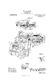
- Figure 1 is a side elevation of a Gordon press equipped with its improved automatic attachments and paper roll showing operating cams for numbering device and cutter;
- Fig. 2 is a similar view of the other side of the press, showing operating cam for operating the inking device and mechanism for operating the feed and perforating rolls;
- Fig. 3 is an enlarged view of the upper portion of Fig. 1 showing the mechanism for feeding the detached sheet and for folding the same;
- Fig. 4 is a transverse section of the folding device showing the means for delivering and stacking the completed sheets of .printed pa- 1 per;
- Fig. 5 is a transverse section of the up- Specification of Letters Patent.
- Fig. 6 is a transverse section through the knives and their supports;
- Fig. 7 is a perspective view of the paper receptacle;
- Fig. 8 is a side elevation of cam which operates the numbering device and also the knife cutter; and
- Fig. 9 represents the camwhich operates the inking rollers.
- 1, 1 are standards or side frames of the form of press commonly known as a Gordon press
- 2 is the oscillating arm which contains the printing form or bed which contains the body of the printed material for the slip
- 4 is the main shaft
- 5 the driving pinion
- 6 is the spur gear
- 7 is the crank shaft
- 8 is one of the crank disks, the other of which is the spur gear 6
- 9 are the connecting rods.
- 10, 10 are brackets attached to the rear of the side frames 1, upon these brackets is secured the roll of paper 11. from which the printed sheets are derived.
- This paper is fed over rollerd2 feed rolls 13 and 14 and roll 15 and finally over the depending take up roller 16, which place it in position to be fed between platen 1'7 and bed 18, where the impression is made, and the numbering and insertion of special characters is performed. Thence the paper is fed over a roll 19 adjust-ably mount-.
- the perforator which comprises the disks 20 provided with teeth 21, operating upon a shaft 22, and in connection with supporting disks 23 for the paper mounted upon the shaft 24:.
- Gears 25, 26 and 27 connect the movements of the perforator with the feed rollers 28 and 29 upon shafts 30 and 31.
- the gear 27 actuates the other gears and its movements are obtained in the manner hereinafter described so as to correspond with those of the cutter.
- Atension. device is shown to compel the paper to travel with the speed of the rollers.
- the folding device acts in conjunction with the movements of the upper knife to fold the sheet centrally immediately after the sheet is detached and V in one line of perforation if there should be more than one.
- the folder is shown to be a vertically movable blade 44 and the mechanism for operating it comprises a lever 49 projecting into the path of movement of a spring catch 51 (see Fig. 3) attached to the upper knife bar so that as the upper knife ascends after cutting ofi the sheet, the catch rises and lifts the inner end of lever 49.
- Lever 49 is pivoted at 49 and consequently its outer end is depressed and through a link 48 (see Fig. 4) and a lever 48 a shaft 46 to which said lever is connected, is rocked.
- Additional levers 46 carried by shaft 46 are connected by spring links 46 with blade 44 and serve to elevate said blade when said shaft is thus rocked, thereby raising instantly the blade 44 which folds the sheet between rapidly revolving rollers 52 which whirl the sheet upward folded flat and it is delivered by the curved plate 53, into a receptacle 54 placed to receive it.
- a resting lug L upon a small plate P receives the bar 49 when it drops after raising the folder and a releasing pin or other projection 51 on the I plate throws back the spring catch 51 as soon as the lever 49 has raised the folder.
- a spring G returns the plate 44.
- This receptacle comprises side pieces P, a long bottom strip P upon which the paper rests, and
- pivoted stop fingers P which serve to aline change speed structure drivenfrom crank wheel 8 (see Figs. 1 and 10) by means of a belt 63 adapted to engage the step pulleys 55 and 56'mounted upon shaft 60; Motion is imparted from shaft 60 to shaft 61 by means of a belt 59 passing over cone pulleys 57 and 58.
- a belt 62 leads from a pulley on shaft 61 to a pulley on the shaft of roll 13.
- the feed rollers adjacent to the knife are .operated by means of the ratchet gear 65 upon the shaft of the lower feed roller, this gearis operated periodically by means of a rack 66, the lower end of which is adjustably pivoted upon a radial guide 67 mounted upon the crank pin 66 at one side of the machine. As the crank rotates to bring the printing surfaces together the rack will ro and once in each revolution of the crank to deliver the printed sheet.
- the feeding rollers for operating the traveling bands which operated by the pulley 67" upon'the rear roller shaft 68, and a belt 69 passing over the idler 70 and over the small pulley 71 upon one end of the main driving shaft 4.
- the folder rollers are rotated more rapidly by means of the pulleys 72, upon the shaft 73 of the upper roller, and the belt 74 pass ing over this pulley and guiding pulleys 75 and 76 an idler roller 70 and pulley 77 upon the main shaft 4.
- the several instrumentalities for supplying the numbering devices With ink and for rotating the numbering disks to bring new numerals in turn into place, and for reciprocating the cutting knife blade are operated by an actuating cam upon the inner faces of the crank disks in the following manner:
- the crank disk at one side of the machine is provided with a cam groove 80 of oblong form, in this groove a roller 81 upon one of the arms 82 pivoted .at 83 upon the side frames of the machine moves.
- Upon these arms 82 are mounted the inking roller 84.
- This cam groove 80 serves first to throw back the inking roller into contact with a second or ductor inking roller 85 mounted in the side frames, and rotated constantly to bring all surfaces into 'contact with the roller 84.
- ⁇ A belt 86 upon a small pulley 87 and passing over the crank disk serves to rapidly rotate the rollers.
- the next movement of these arms brings the inking roller. rapidly on the numbering disks 88 and supplies them with ink to make the impression.
- the numbering devices comprise disks 88 supplied with the required numerals to be used in turn upon the sheets of paper. They are mounted upon ashaft 89 fixed in the brackets 90 upon the side frames, a ratchet 91 for each disk or set of disks is operated. to move a new figure into position for making the impression at eachrevolution of the machine. This is accomplished by means of a parallel rock shaft 92 and pawls 93 and short arms 94 carried .by the rock shaft and to which the pawls are pivotally connected.
- the rock shaft is oscillated by means of a tate the feed roller after each impression carry the detached sheet to the folder are 7 connect-ing rod 95, a bell crank 96, pivoted to the frame and provided with a roller 97 moving in the cam groove 98 in the crank disk 8.
- the connecting rod 95 is adjustably connected at 99 with an arm of the bell crank to accommodate the movement to the diameter of the numbering disks and number of figures spaced upon their peripheries.
- the device for operating the knife blade to cut off the paper sheet must operate alternately with the action of the numbering disks. Hence as the machine opens after the impression has been made and the paper is fed forward to the limit of its movement by the feeding gears before mentioned, the paper sheet is immediately out 01f.
- the action of the cutting knife is therefore most naturally controlled by the cam which operates the pawl that rotates the numbering disks, but at later period.
- a lever 100 pivoted at 101 upon one of the side frames is provided with a roller 102 which enters the cam groove 98 upon the opposite side to the roller 97 of the bell crank which operates the numbering disks.
- the projecting end of the lever 100 is pivoted to the connecting rod 103 and this rod is secured to the bell crank 104, pivoted to the side frame at 105 and to the knife bar at 105*.
- a link 106 pivoted at 106 upon the other side frame and to the knife bar at 106 cooperates with the bell crank 101 to give the knife a vertical and also drawing movement which most easily cuts the paper.
- Guiding plates 107 and 108 above the paper serve to deliver it from the feed rolls to the knife, and a stop plate 110 in the frame 43 of the folder limits the movement of the detached sheet when thrown into the folding frame.
- a printing press having a frame and stationary platen, a main shaft, a parallel crank shaft and crank disks thereon, and oscillating bed and connecting rods, of a support for apaper roll upon said frame, guide and take up rolls therefor, a numbering device comprising rotatable numbering disks, perforating rolls and a cutting blade, and feed rolls intermediate between the perforating rolls and cutting blade, a cam upon one of the crank disks, mechanism operatively connected with said cam to alternately rotate said numbering disks, and reciprocate said out ting blade, a radially adjustable crank pin upon one of said cranks, and rack and rolls, said rack being arranged to move said rolls alternately with the movement of the knife blade, substantially as described.
- a numbering device comprising rotatable numbering disks and. actuating ratchet and pawl therefor, a bracket upon the frame, perforating and feed rolls on said bracket, a reciprocating knife blade, a cam upon one of said crank wheels, a lever pivoted on said frame and actuated by said cam to operate said pawl and ratchet, a second lever pivoted on said frame and actuated by said cam to reciprocate said knife to cut the paper, alternately with the movements of the numbering disks, a cam upon one of the crank wheels, an inking device pivoted on said frame adjacent to said numbering disks and having an extended arm, engaging with said cam, whereby the movements of said inking device alternate with the movement-s of said numbering device, gearing for rotating the perforating disks and upper feed rolls in unison, an adjustable crank pin
Description
W. F. G. FOSTER.
PRINTING PRESS.
APPLICATION FILED AUG. 19, 1907.
Patented June 11, 1912.
3 SHEETS-SHEET 1.
COLUMBIA PLANOGRAPN CDQWASHINGTONV D. c.
W. F G. FOSTER.
PRINTING PRESS.
APPLICATION rum) AUG.19, 1907.
1,029,484, Patented June 11, 1912.
3 SHEETS-SHEET 2.
7Z ii7wsses V /4 I y 76M 7 0 2 fidlorizey W. P. C. FOSTER.
PRINTING PRESS.
APPLICATION FILED AUG.19, 1907.
1,029,434, Patented June 11, 1912.
. 3 SHEETS-SHEET 3.
coLuMulA ILANOGRM'II u v. \msmmn-nw. n. cv
n'rr
WILLIAM FREDERICK CHARLES FOSTER, OF WAWANESA, MANITOBA, CANADA.
PRINTING-PRESS.
To all whom it may concern:
Be it known that I, WILLIAM FREDERICK CI-IARLEs Fos'rEn, a citizen of Canada, and resident of Wawanesa, Province of Manitoba, Canada, have invented certain new and useful Improvements in Printing- Presses, of which I hereby declare the following to be a full, clear, and exact description, such as will enableothers skilled in the art to which it appertains to make and use the same. 7
The objects of the invention are to provide instrumentalities for printing, numbering folding and perforating upon a Gordon or other press, such special and small work as the counter sales slips, employed in mercantile houses, dodgers, sale bills, note and letter heads and analogous productions and to produce them continuously from a roll of paper and thereby greatly increase the efliciency and speed of production of the press.
The objects are further to provide simple forms of automatically operating mechanism to obtain these results and to make the mechanism attachable to a Gordon press and operated thereby and in this manner to utilize the general movements of the press to accomplish work hitherto done only by hand and without greatly increasing the cost of the machine.
The invention consists in the hereinafter enumerated devices for feeding the paper, printing and numbering the same for perforating and cutting it into sheets of the required size and for folding and discharging from the machine, and in the various details of construction and combination and arrangement of parts as hereinafter described, exemplified in the accompanying drawings and specifically pointed out in the claims.
In the accompanying drawings, Figure 1 is a side elevation of a Gordon press equipped with its improved automatic attachments and paper roll showing operating cams for numbering device and cutter; Fig. 2 is a similar view of the other side of the press, showing operating cam for operating the inking device and mechanism for operating the feed and perforating rolls; Fig. 3 is an enlarged view of the upper portion of Fig. 1 showing the mechanism for feeding the detached sheet and for folding the same; Fig. 4 is a transverse section of the folding device showing the means for delivering and stacking the completed sheets of .printed pa- 1 per; Fig. 5 is a transverse section of the up- Specification of Letters Patent.
Application filed August 19, 1907.
Patented June 11, 1912.
Serial No. 389,155.
sheet will be folded and delivered almost instantly after being cut ofi" from the strip; Fig. 6 is a transverse section through the knives and their supports; Fig. 7 is a perspective view of the paper receptacle; Fig. 8 is a side elevation of cam which operates the numbering device and also the knife cutter; and Fig. 9 represents the camwhich operates the inking rollers.
In these views, 1, 1 are standards or side frames of the form of press commonly known as a Gordon press, 2 is the oscillating arm which contains the printing form or bed which contains the body of the printed material for the slip, 4 is the main shaft, 5 the driving pinion, 6 is the spur gear and 7 is the crank shaft, 8 is one of the crank disks, the other of which is the spur gear 6, 9, 9 are the connecting rods. These are the usual features of the Gordon press. The automatic mechanism connected therewith and deriving their movement therefrom may be described in detail as follows: 10, 10 are brackets attached to the rear of the side frames 1, upon these brackets is secured the roll of paper 11. from which the printed sheets are derived. This paper is fed over rollerd2 feed rolls 13 and 14 and roll 15 and finally over the depending take up roller 16, which place it in position to be fed between platen 1'7 and bed 18, where the impression is made, and the numbering and insertion of special characters is performed. Thence the paper is fed over a roll 19 adjust-ably mount-.
ed in swinging arms 19 by means of which the relative length of the sheet and the position of the cut are determined and over idler 19". Next shown is the perforator which comprises the disks 20 provided with teeth 21, operating upon a shaft 22, and in connection with supporting disks 23 for the paper mounted upon the shaft 24:. Gears 25, 26 and 27 connect the movements of the perforator with the feed rollers 28 and 29 upon shafts 30 and 31. The gear 27 actuates the other gears and its movements are obtained in the manner hereinafter described so as to correspond with those of the cutter. Atension. device is shown to compel the paper to travel with the speed of the rollers. This consists of a lever 32 fulcrumed upon a cross bar 33 or upon the frame, and resting upon the shaft 30, a set screw 34 in the bar adjusts the tension. This makes the engagement of the rolls positive. The cutting knife blade 35 .is mounted upon a transverse bar 36 in guides 37 and operates against the lower knife blade 38, fixed upon the cross bar 39tand adjusted by means of screws 40 relatively to the cuttin edge of the other knife. Assoon as cut 0 the sheet of printed paper is instantly transferred to the folding device by means of rollers 41 and. 42 upon a frame 43' and bands 44 which are in constant rearward motion. The folding device acts in conjunction with the movements of the upper knife to fold the sheet centrally immediately after the sheet is detached and V in one line of perforation if there should be more than one. The folder is shown to be a vertically movable blade 44 and the mechanism for operating it comprises a lever 49 projecting into the path of movement of a spring catch 51 (see Fig. 3) attached to the upper knife bar so that as the upper knife ascends after cutting ofi the sheet, the catch rises and lifts the inner end of lever 49. Lever 49 is pivoted at 49 and consequently its outer end is depressed and through a link 48 (see Fig. 4) and a lever 48 a shaft 46 to which said lever is connected, is rocked. Additional levers 46 carried by shaft 46 are connected by spring links 46 with blade 44 and serve to elevate said blade when said shaft is thus rocked, thereby raising instantly the blade 44 which folds the sheet between rapidly revolving rollers 52 which whirl the sheet upward folded flat and it is delivered by the curved plate 53, into a receptacle 54 placed to receive it. A resting lug L upon a small plate P receives the bar 49 when it drops after raising the folder and a releasing pin or other projection 51 on the I plate throws back the spring catch 51 as soon as the lever 49 has raised the folder. A spring G returns the plate 44. This receptacle comprises side pieces P, a long bottom strip P upon which the paper rests, and
pivoted stop fingers P which serve to aline change speed structure drivenfrom crank wheel 8 (see Figs. 1 and 10) by means of a belt 63 adapted to engage the step pulleys 55 and 56'mounted upon shaft 60; Motion is imparted from shaft 60 to shaft 61 by means of a belt 59 passing over cone pulleys 57 and 58. A belt 62 leads from a pulley on shaft 61 to a pulley on the shaft of roll 13. The feed rollers adjacent to the knife are .operated by means of the ratchet gear 65 upon the shaft of the lower feed roller, this gearis operated periodically by means of a rack 66, the lower end of which is adjustably pivoted upon a radial guide 67 mounted upon the crank pin 66 at one side of the machine. As the crank rotates to bring the printing surfaces together the rack will ro and once in each revolution of the crank to deliver the printed sheet. The feeding rollers for operating the traveling bands which operated by the pulley 67" upon'the rear roller shaft 68, and a belt 69 passing over the idler 70 and over the small pulley 71 upon one end of the main driving shaft 4. The folder rollers are rotated more rapidly by means of the pulleys 72, upon the shaft 73 of the upper roller, and the belt 74 pass ing over this pulley and guiding pulleys 75 and 76 an idler roller 70 and pulley 77 upon the main shaft 4.
The several instrumentalities for supplying the numbering devices With ink and for rotating the numbering disks to bring new numerals in turn into place, and for reciprocating the cutting knife blade are operated by an actuating cam upon the inner faces of the crank disks in the following manner: The crank disk at one side of the machine is provided with a cam groove 80 of oblong form, in this groove a roller 81 upon one of the arms 82 pivoted .at 83 upon the side frames of the machine moves. Upon these arms 82 are mounted the inking roller 84. This cam groove 80 serves first to throw back the inking roller into contact with a second or ductor inking roller 85 mounted in the side frames, and rotated constantly to bring all surfaces into 'contact with the roller 84. \A belt 86 upon a small pulley 87 and passing over the crank disk serves to rapidly rotate the rollers. The next movement of these arms brings the inking roller. rapidly on the numbering disks 88 and supplies them with ink to make the impression.
The numbering devices comprise disks 88 supplied with the required numerals to be used in turn upon the sheets of paper. They are mounted upon ashaft 89 fixed in the brackets 90 upon the side frames, a ratchet 91 for each disk or set of disks is operated. to move a new figure into position for making the impression at eachrevolution of the machine. This is accomplished by means of a parallel rock shaft 92 and pawls 93 and short arms 94 carried .by the rock shaft and to which the pawls are pivotally connected. The rock shaft is oscillated by means of a tate the feed roller after each impression carry the detached sheet to the folder are 7 connect-ing rod 95, a bell crank 96, pivoted to the frame and provided with a roller 97 moving in the cam groove 98 in the crank disk 8. The connecting rod 95 is adjustably connected at 99 with an arm of the bell crank to accommodate the movement to the diameter of the numbering disks and number of figures spaced upon their peripheries.
The device for operating the knife blade to cut off the paper sheet must operate alternately with the action of the numbering disks. Hence as the machine opens after the impression has been made and the paper is fed forward to the limit of its movement by the feeding gears before mentioned, the paper sheet is immediately out 01f. The action of the cutting knife is therefore most naturally controlled by the cam which operates the pawl that rotates the numbering disks, but at later period. To accomplish this movement a lever 100 pivoted at 101 upon one of the side frames is provided with a roller 102 which enters the cam groove 98 upon the opposite side to the roller 97 of the bell crank which operates the numbering disks. The projecting end of the lever 100 is pivoted to the connecting rod 103 and this rod is secured to the bell crank 104, pivoted to the side frame at 105 and to the knife bar at 105*. A link 106 pivoted at 106 upon the other side frame and to the knife bar at 106 cooperates with the bell crank 101 to give the knife a vertical and also drawing movement which most easily cuts the paper.
Guiding plates 107 and 108 above the paper serve to deliver it from the feed rolls to the knife, and a stop plate 110 in the frame 43 of the folder limits the movement of the detached sheet when thrown into the folding frame.
Having described the invention what I claim as new and desire to secure by Letters Patent is 1. The combination wit-h a printing press, having a frame and stationary platen, a main shaft, a parallel crank shaft and crank disks thereon, and oscillating bed and connecting rods, of a support for apaper roll upon said frame, guide and take up rolls therefor, a numbering device comprising rotatable numbering disks, perforating rolls and a cutting blade, and feed rolls intermediate between the perforating rolls and cutting blade, a cam upon one of the crank disks, mechanism operatively connected with said cam to alternately rotate said numbering disks, and reciprocate said out ting blade, a radially adjustable crank pin upon one of said cranks, and rack and rolls, said rack being arranged to move said rolls alternately with the movement of the knife blade, substantially as described.
2. In a Gordon press having a platen, a
frame and movable bed and crank shaft, crank wheels and connecting rods, therefor, the combination therewith, of a support for a roll of paper, lower guide and feed rolls therefor, a numbering device comprising rotatable numbering disks and. actuating ratchet and pawl therefor, a bracket upon the frame, perforating and feed rolls on said bracket, a reciprocating knife blade, a cam upon one of said crank wheels, a lever pivoted on said frame and actuated by said cam to operate said pawl and ratchet, a second lever pivoted on said frame and actuated by said cam to reciprocate said knife to cut the paper, alternately with the movements of the numbering disks, a cam upon one of the crank wheels, an inking device pivoted on said frame adjacent to said numbering disks and having an extended arm, engaging with said cam, whereby the movements of said inking device alternate with the movement-s of said numbering device, gearing for rotating the perforating disks and upper feed rolls in unison, an adjustable crank pin on one of said crank wheels and a rack and gear arranged to operate said rolls, and a length adjusting roll located between the numbering disks and the perforating disks, substantially as described.
3. The combination with a printing press having a frame and platen, and a crank shaft and crank wheels thereon, of paper feed rolls upon said frame, speed rolls on the frame, a driving belt connecting one of said crank wheels with one of said speed rolls, and a driving belt connecting one of said speed rolls and one of said feed rolls, an idler roller on the frame, a take up roller in a fold of the paper, a numbering device adjacent to the platen, a length adjusting roll over which the paper passes, perforating and upper feed rolls, a knife blade, and instrumentalities operatively connected with the crank shaft of the press for operating the numbering device, the upper feed and herforating rolls, and the knife blade, substantially as described.
In testimony whereof I hereunto set my hand this tenth day of April 1907.
WILLIAM FREDERICK CHARLES FOSTER.
In presence of- CHARLES LORRAINE ATKINSON, WILLIAM SMITH FosTER.
Copies of this patent may be obtained for five cents each, by addressing the Commissioner of Patents, Washington, D. G.
Priority Applications (1)
| Application Number | Priority Date | Filing Date | Title |
|---|---|---|---|
| US38915507A US1029434A (en) | 1907-08-19 | 1907-08-19 | Printing-press. |
Applications Claiming Priority (1)
| Application Number | Priority Date | Filing Date | Title |
|---|---|---|---|
| US38915507A US1029434A (en) | 1907-08-19 | 1907-08-19 | Printing-press. |
Publications (1)
| Publication Number | Publication Date |
|---|---|
| US1029434A true US1029434A (en) | 1912-06-11 |
Family
ID=3097727
Family Applications (1)
| Application Number | Title | Priority Date | Filing Date |
|---|---|---|---|
| US38915507A Expired - Lifetime US1029434A (en) | 1907-08-19 | 1907-08-19 | Printing-press. |
Country Status (1)
| Country | Link |
|---|---|
| US (1) | US1029434A (en) |
Cited By (1)
| Publication number | Priority date | Publication date | Assignee | Title |
|---|---|---|---|---|
| US3406628A (en) * | 1966-09-20 | 1968-10-22 | Heller Roberts Instr Corp | Web feed control means in multiple numbering and imprinting press |
-
1907
- 1907-08-19 US US38915507A patent/US1029434A/en not_active Expired - Lifetime
Cited By (1)
| Publication number | Priority date | Publication date | Assignee | Title |
|---|---|---|---|---|
| US3406628A (en) * | 1966-09-20 | 1968-10-22 | Heller Roberts Instr Corp | Web feed control means in multiple numbering and imprinting press |
Similar Documents
| Publication | Publication Date | Title |
|---|---|---|
| US796707A (en) | Printing-press. | |
| US1029434A (en) | Printing-press. | |
| US1071853A (en) | Means for folding and wrapping newspapers and the like. | |
| US465427A (en) | Joseph l | |
| US999980A (en) | Cutting and folding device for printing-presses. | |
| US1287923A (en) | Printing-press. | |
| US308119A (en) | Paper-feeding machine | |
| US1131268A (en) | Printing-press. | |
| US500115A (en) | crowell | |
| US723683A (en) | Feed-controlling attachment for printing-presses. | |
| US932250A (en) | Printing-machine. | |
| US906484A (en) | Wrapping-machine. | |
| US535282A (en) | Printing-press | |
| US387500A (en) | Machine | |
| US287239A (en) | Fifths to charles w | |
| US516317A (en) | Perforating attachment for printing-presses | |
| US733325A (en) | Printing-press. | |
| US557381A (en) | Printing-press | |
| US138028A (en) | Improvement in postal-card machines | |
| US286382A (en) | beissaed | |
| US221546A (en) | Improvement in machines for printing paper bags | |
| US220977A (en) | Improvement in addressing attachments for printing-machines | |
| US614919A (en) | wolfe | |
| US541318A (en) | Newspaper-wrapping machine | |
| US1129844A (en) | Automatic stop device for printing-presses. |