US10288322B2 - Heat storage devices for solar steam generation, and associated systems and methods - Google Patents
Heat storage devices for solar steam generation, and associated systems and methods Download PDFInfo
- Publication number
- US10288322B2 US10288322B2 US14/920,700 US201514920700A US10288322B2 US 10288322 B2 US10288322 B2 US 10288322B2 US 201514920700 A US201514920700 A US 201514920700A US 10288322 B2 US10288322 B2 US 10288322B2
- Authority
- US
- United States
- Prior art keywords
- working fluid
- flow
- plates
- storage housing
- heat storage
- Prior art date
- Legal status (The legal status is an assumption and is not a legal conclusion. Google has not performed a legal analysis and makes no representation as to the accuracy of the status listed.)
- Active, expires
Links
- 238000000034 method Methods 0.000 title claims abstract description 29
- 238000005338 heat storage Methods 0.000 title abstract description 86
- 239000012530 fluid Substances 0.000 claims abstract description 144
- 238000003860 storage Methods 0.000 claims abstract description 21
- 238000009835 boiling Methods 0.000 claims abstract description 3
- 238000004891 communication Methods 0.000 claims description 7
- 230000001276 controlling effect Effects 0.000 claims 3
- 230000001105 regulatory effect Effects 0.000 claims 1
- 238000005516 engineering process Methods 0.000 description 44
- 238000012546 transfer Methods 0.000 description 23
- 238000004519 manufacturing process Methods 0.000 description 16
- 239000000463 material Substances 0.000 description 13
- 230000008569 process Effects 0.000 description 10
- 239000012778 molding material Substances 0.000 description 9
- XLYOFNOQVPJJNP-UHFFFAOYSA-N water Substances O XLYOFNOQVPJJNP-UHFFFAOYSA-N 0.000 description 7
- 238000009826 distribution Methods 0.000 description 6
- 230000008901 benefit Effects 0.000 description 5
- 238000010438 heat treatment Methods 0.000 description 5
- 239000003129 oil well Substances 0.000 description 5
- 230000008859 change Effects 0.000 description 4
- 238000009413 insulation Methods 0.000 description 4
- 238000002844 melting Methods 0.000 description 4
- 230000008018 melting Effects 0.000 description 4
- 238000000465 moulding Methods 0.000 description 4
- 230000015572 biosynthetic process Effects 0.000 description 3
- 230000004888 barrier function Effects 0.000 description 2
- 238000006243 chemical reaction Methods 0.000 description 2
- 238000001816 cooling Methods 0.000 description 2
- 230000003247 decreasing effect Effects 0.000 description 2
- 230000004907 flux Effects 0.000 description 2
- 230000006870 function Effects 0.000 description 2
- 238000009434 installation Methods 0.000 description 2
- 230000005855 radiation Effects 0.000 description 2
- 238000011084 recovery Methods 0.000 description 2
- 238000000926 separation method Methods 0.000 description 2
- 239000008186 active pharmaceutical agent Substances 0.000 description 1
- 230000009286 beneficial effect Effects 0.000 description 1
- 230000005540 biological transmission Effects 0.000 description 1
- 230000001413 cellular effect Effects 0.000 description 1
- 239000000919 ceramic Substances 0.000 description 1
- 238000005253 cladding Methods 0.000 description 1
- 239000011248 coating agent Substances 0.000 description 1
- 238000000576 coating method Methods 0.000 description 1
- 238000005336 cracking Methods 0.000 description 1
- 230000007423 decrease Effects 0.000 description 1
- 230000001934 delay Effects 0.000 description 1
- 238000011161 development Methods 0.000 description 1
- 230000000694 effects Effects 0.000 description 1
- 239000008393 encapsulating agent Substances 0.000 description 1
- 238000000605 extraction Methods 0.000 description 1
- 239000002803 fossil fuel Substances 0.000 description 1
- 239000000446 fuel Substances 0.000 description 1
- 230000005055 memory storage Effects 0.000 description 1
- 230000003287 optical effect Effects 0.000 description 1
- 239000004033 plastic Substances 0.000 description 1
- 238000010248 power generation Methods 0.000 description 1
- 238000012545 processing Methods 0.000 description 1
- 230000001737 promoting effect Effects 0.000 description 1
- 150000003839 salts Chemical class 0.000 description 1
- 238000007493 shaping process Methods 0.000 description 1
- 239000007787 solid Substances 0.000 description 1
- 230000001502 supplementing effect Effects 0.000 description 1
- 230000008646 thermal stress Effects 0.000 description 1
Images


Classifications
-
- B—PERFORMING OPERATIONS; TRANSPORTING
- B23—MACHINE TOOLS; METAL-WORKING NOT OTHERWISE PROVIDED FOR
- B23P—METAL-WORKING NOT OTHERWISE PROVIDED FOR; COMBINED OPERATIONS; UNIVERSAL MACHINE TOOLS
- B23P15/00—Making specific metal objects by operations not covered by a single other subclass or a group in this subclass
- B23P15/26—Making specific metal objects by operations not covered by a single other subclass or a group in this subclass heat exchangers or the like
-
- F—MECHANICAL ENGINEERING; LIGHTING; HEATING; WEAPONS; BLASTING
- F24—HEATING; RANGES; VENTILATING
- F24S—SOLAR HEAT COLLECTORS; SOLAR HEAT SYSTEMS
- F24S60/00—Arrangements for storing heat collected by solar heat collectors
-
- B—PERFORMING OPERATIONS; TRANSPORTING
- B28—WORKING CEMENT, CLAY, OR STONE
- B28B—SHAPING CLAY OR OTHER CERAMIC COMPOSITIONS; SHAPING SLAG; SHAPING MIXTURES CONTAINING CEMENTITIOUS MATERIAL, e.g. PLASTER
- B28B7/00—Moulds; Cores; Mandrels
- B28B7/16—Moulds for making shaped articles with cavities or holes open to the surface, e.g. with blind holes
- B28B7/18—Moulds for making shaped articles with cavities or holes open to the surface, e.g. with blind holes the holes passing completely through the article
- B28B7/183—Moulds for making shaped articles with cavities or holes open to the surface, e.g. with blind holes the holes passing completely through the article for building blocks or similar block-shaped objects
-
- B—PERFORMING OPERATIONS; TRANSPORTING
- B28—WORKING CEMENT, CLAY, OR STONE
- B28B—SHAPING CLAY OR OTHER CERAMIC COMPOSITIONS; SHAPING SLAG; SHAPING MIXTURES CONTAINING CEMENTITIOUS MATERIAL, e.g. PLASTER
- B28B7/00—Moulds; Cores; Mandrels
- B28B7/34—Moulds, cores, or mandrels of special material, e.g. destructible materials
- B28B7/342—Moulds, cores, or mandrels of special material, e.g. destructible materials which are at least partially destroyed, e.g. broken, molten, before demoulding; Moulding surfaces or spaces shaped by, or in, the ground, or sand or soil, whether bound or not; Cores consisting at least mainly of sand or soil, whether bound or not
-
- B—PERFORMING OPERATIONS; TRANSPORTING
- B28—WORKING CEMENT, CLAY, OR STONE
- B28B—SHAPING CLAY OR OTHER CERAMIC COMPOSITIONS; SHAPING SLAG; SHAPING MIXTURES CONTAINING CEMENTITIOUS MATERIAL, e.g. PLASTER
- B28B7/00—Moulds; Cores; Mandrels
- B28B7/34—Moulds, cores, or mandrels of special material, e.g. destructible materials
- B28B7/346—Manufacture of moulds
-
- F—MECHANICAL ENGINEERING; LIGHTING; HEATING; WEAPONS; BLASTING
- F22—STEAM GENERATION
- F22B—METHODS OF STEAM GENERATION; STEAM BOILERS
- F22B1/00—Methods of steam generation characterised by form of heating method
- F22B1/006—Methods of steam generation characterised by form of heating method using solar heat
-
- F—MECHANICAL ENGINEERING; LIGHTING; HEATING; WEAPONS; BLASTING
- F28—HEAT EXCHANGE IN GENERAL
- F28D—HEAT-EXCHANGE APPARATUS, NOT PROVIDED FOR IN ANOTHER SUBCLASS, IN WHICH THE HEAT-EXCHANGE MEDIA DO NOT COME INTO DIRECT CONTACT
- F28D20/00—Heat storage plants or apparatus in general; Regenerative heat-exchange apparatus not covered by groups F28D17/00 or F28D19/00
- F28D20/0056—Heat storage plants or apparatus in general; Regenerative heat-exchange apparatus not covered by groups F28D17/00 or F28D19/00 using solid heat storage material
-
- F—MECHANICAL ENGINEERING; LIGHTING; HEATING; WEAPONS; BLASTING
- F28—HEAT EXCHANGE IN GENERAL
- F28F—DETAILS OF HEAT-EXCHANGE AND HEAT-TRANSFER APPARATUS, OF GENERAL APPLICATION
- F28F9/00—Casings; Header boxes; Auxiliary supports for elements; Auxiliary members within casings
- F28F9/02—Header boxes; End plates
- F28F9/026—Header boxes; End plates with static flow control means, e.g. with means for uniformly distributing heat exchange media into conduits
- F28F9/027—Header boxes; End plates with static flow control means, e.g. with means for uniformly distributing heat exchange media into conduits in the form of distribution pipes
- F28F9/0273—Header boxes; End plates with static flow control means, e.g. with means for uniformly distributing heat exchange media into conduits in the form of distribution pipes with multiple holes
-
- F—MECHANICAL ENGINEERING; LIGHTING; HEATING; WEAPONS; BLASTING
- F28—HEAT EXCHANGE IN GENERAL
- F28D—HEAT-EXCHANGE APPARATUS, NOT PROVIDED FOR IN ANOTHER SUBCLASS, IN WHICH THE HEAT-EXCHANGE MEDIA DO NOT COME INTO DIRECT CONTACT
- F28D20/00—Heat storage plants or apparatus in general; Regenerative heat-exchange apparatus not covered by groups F28D17/00 or F28D19/00
- F28D2020/0004—Particular heat storage apparatus
- F28D2020/0008—Particular heat storage apparatus the heat storage material being enclosed in plate-like or laminated elements, e.g. in plates having internal compartments
-
- F—MECHANICAL ENGINEERING; LIGHTING; HEATING; WEAPONS; BLASTING
- F28—HEAT EXCHANGE IN GENERAL
- F28D—HEAT-EXCHANGE APPARATUS, NOT PROVIDED FOR IN ANOTHER SUBCLASS, IN WHICH THE HEAT-EXCHANGE MEDIA DO NOT COME INTO DIRECT CONTACT
- F28D20/00—Heat storage plants or apparatus in general; Regenerative heat-exchange apparatus not covered by groups F28D17/00 or F28D19/00
- F28D2020/0065—Details, e.g. particular heat storage tanks, auxiliary members within tanks
- F28D2020/0082—Multiple tanks arrangements, e.g. adjacent tanks, tank in tank
-
- F—MECHANICAL ENGINEERING; LIGHTING; HEATING; WEAPONS; BLASTING
- F28—HEAT EXCHANGE IN GENERAL
- F28F—DETAILS OF HEAT-EXCHANGE AND HEAT-TRANSFER APPARATUS, OF GENERAL APPLICATION
- F28F2265/00—Safety or protection arrangements; Arrangements for preventing malfunction
- F28F2265/26—Safety or protection arrangements; Arrangements for preventing malfunction for allowing differential expansion between elements
-
- Y—GENERAL TAGGING OF NEW TECHNOLOGICAL DEVELOPMENTS; GENERAL TAGGING OF CROSS-SECTIONAL TECHNOLOGIES SPANNING OVER SEVERAL SECTIONS OF THE IPC; TECHNICAL SUBJECTS COVERED BY FORMER USPC CROSS-REFERENCE ART COLLECTIONS [XRACs] AND DIGESTS
- Y02—TECHNOLOGIES OR APPLICATIONS FOR MITIGATION OR ADAPTATION AGAINST CLIMATE CHANGE
- Y02E—REDUCTION OF GREENHOUSE GAS [GHG] EMISSIONS, RELATED TO ENERGY GENERATION, TRANSMISSION OR DISTRIBUTION
- Y02E10/00—Energy generation through renewable energy sources
- Y02E10/40—Solar thermal energy, e.g. solar towers
-
- Y—GENERAL TAGGING OF NEW TECHNOLOGICAL DEVELOPMENTS; GENERAL TAGGING OF CROSS-SECTIONAL TECHNOLOGIES SPANNING OVER SEVERAL SECTIONS OF THE IPC; TECHNICAL SUBJECTS COVERED BY FORMER USPC CROSS-REFERENCE ART COLLECTIONS [XRACs] AND DIGESTS
- Y02—TECHNOLOGIES OR APPLICATIONS FOR MITIGATION OR ADAPTATION AGAINST CLIMATE CHANGE
- Y02E—REDUCTION OF GREENHOUSE GAS [GHG] EMISSIONS, RELATED TO ENERGY GENERATION, TRANSMISSION OR DISTRIBUTION
- Y02E60/00—Enabling technologies; Technologies with a potential or indirect contribution to GHG emissions mitigation
- Y02E60/14—Thermal energy storage
-
- Y02E60/142—
-
- Y—GENERAL TAGGING OF NEW TECHNOLOGICAL DEVELOPMENTS; GENERAL TAGGING OF CROSS-SECTIONAL TECHNOLOGIES SPANNING OVER SEVERAL SECTIONS OF THE IPC; TECHNICAL SUBJECTS COVERED BY FORMER USPC CROSS-REFERENCE ART COLLECTIONS [XRACs] AND DIGESTS
- Y02—TECHNOLOGIES OR APPLICATIONS FOR MITIGATION OR ADAPTATION AGAINST CLIMATE CHANGE
- Y02E—REDUCTION OF GREENHOUSE GAS [GHG] EMISSIONS, RELATED TO ENERGY GENERATION, TRANSMISSION OR DISTRIBUTION
- Y02E70/00—Other energy conversion or management systems reducing GHG emissions
- Y02E70/30—Systems combining energy storage with energy generation of non-fossil origin
Definitions
- the present technology is directed generally to techniques for storing the energy produced by solar concentrators, including methods and devices for economical and robust heat storage, and associated systems.
- One such technique includes injecting steam into an oil-bearing formation to free up the oil.
- steam can be injected into an oil well and/or in the vicinity of the oil well. The high temperature of the steam heats up the adjacent formation and oil within the formation, thereby decreasing the viscosity of the oil and enabling the oil to more easily flow to the surface of the oil field.
- steam can be generated from solar power using, for example, solar power systems with concentrators (e.g., mirrors) that direct solar energy to a receiver (e.g., piping that contains a working fluid).
- the concentrators focus solar energy from a relatively large area (e.g., the insolated area of the mirror) to a relatively small area of the receiver (e.g., axial cross-sectional area of a pipe), thereby producing a relatively high energy flux at the receiver.
- the working fluid changes its phase (e.g., from water to steam) while flowing through the receiver that is subjected to a high energy flux.
- a steady supply of steam is preferred at an oil field for a steady production of oil.
- the production of steam by solar concentrators is a function of solar insolation, which is intrinsically cyclical (e.g., day/night, sunny/cloudy, winter/summer, etc.). Therefore, in some field applications, the solar power systems include solar heat storage devices that can store excess energy when the insolation is high and release energy when the insolation is small or nonexistent. An example of such a system is described below.
- FIG. 1 is a schematic view of a system 10 for generating steam in accordance with the prior art.
- the sun 13 emits solar radiation 14 toward a curved concentrator (e.g., a mirror) 11 that has a line focus corresponding to the location of a receiver 12 .
- a curved concentrator e.g., a mirror
- the solar radiation 14 from a relatively large curved concentrator 11 is focused on a relatively small area of the receiver 12 .
- the highly concentrated solar energy causes a phase change from water W to steam S.
- a first portion of the steam (S 1 ) is directed to an oil well 18 or its vicinity and a second portion of the steam (S 2 ) is directed to a heat exchanger 15 .
- a valve V maintains a suitable balance between the flows of steam S 1 and S 2 .
- the valve V can be fully closed when the steam production is relatively low, and all available steam is directed to the oil well 18 .
- the second portion of steam S 2 enters the heat exchanger 15 , exchanges thermal energy E with a working fluid WF, which can be, for example, steam or thermal oil, and returns to the entrance of the receiver 12 .
- a working fluid WF which can be, for example, steam or thermal oil
- the temperature of the second portion of steam (S 2 ) may still be higher than that of the water W, thereby decreasing the amount of solar energy that the water W would otherwise require to change its phase to steam.
- the temperature of the second portion of steam (S 2 ) is sufficiently high to transfer thermal energy to the working fluid WF in the heat exchanger 15 .
- the working fluid WF then transfers thermal energy to a heat storage unit 16 .
- the temperature of the second portion of steam (S 2 ) is also relatively low, and the second portion of steam (S 2 ) receives thermal energy from the working fluid WF in the heat exchanger 15 .
- thermal energy that is stored in the heat storage device 16 when the insolation is relatively high is transferred back to steam when the insolation is relatively low. This transfer of thermal energy to and from the heat storage device 16 promotes a more even flow of the first portion of steam S 1 at the oil well 18 .
- FIG. 2 illustrates a portion 20 of a heat storage device in accordance with the prior art.
- the portion 20 of the heat storage device e.g., the heat storage device 16 of FIG. 1
- concrete blocks 22 surround pipes 21 .
- the temperature of the working fluid WF is relatively high
- the flow of the working fluid WF through the pipes 21 heats up the adjacent concrete blocks 22 .
- This part of the thermal cycle generally occurs during a period of high insolation.
- the concrete blocks 22 heat the working fluid WF, which then transfers energy back to the water/steam in the heat exchanger 15 ( FIG. 1 ). Accordingly, the heat storage device 16 recovers some thermal energy that would otherwise be wasted due to the cyclical nature of insolation.
- the illustrated system has some drawbacks.
- the pipes 21 are relatively expensive, making the overall heat storage device 16 expensive. Due to a relatively dense distribution of the pipes 21 , the amount of working fluid WF contained in the heat storage device 16 can be relatively high which further increases cost of the heat storage device 16 . Furthermore, the rate of heat transfer can be poor at the junction between the pipes 21 and the concrete blocks 22 , therefore reducing the efficiency of the heat storage process.
- FIG. 3 is a partially schematic cross-sectional view of another heat storage device 30 in accordance with the prior art.
- a first working fluid WF 1 e.g., steam or oil
- a second working fluid WF 2 e.g., oil
- the second working fluid WF 2 can be heated by the first working fluid WF 1 during periods of high insolation and the first working fluid WF 1 can be heated by the second working fluid WF 2 during periods of low insolation.
- the second working fluid WF 2 can absorb relatively large amount of heat without having to be pressurized due to its relatively high heat capacity and boiling point.
- the second working fluid WF 2 is generally expensive, relatively inexpensive concrete plates 31 can be inserted in the heat storage device 30 to reduce the required volume of the second working fluid WF 2 inside the heat storage device 30 .
- pumps 32 circulate the second working fluid WF 2 within the heat storage device 30 .
- the flow of the second working fluid WF 2 around the concrete plates 31 can still vary significantly, resulting in thermal non-uniformities when heating/cooling the concrete plates 31 , thereby reducing the thermal capacity of the system.
- the pumps 32 are potential points of failure within the overall system. Accordingly, there remains a need for inexpensive and thermally efficient heat storage devices that can facilitate solar heat storage and recovery.
- FIG. 1 is a schematic view of a system for generating steam in accordance with the prior art.
- FIG. 2 illustrates a portion of a heat storage device in accordance with the prior art.
- FIG. 3 is a partially schematic cross-sectional view of a heat storage device in accordance with the prior art.
- FIGS. 4A-4C are partially schematic cross-sectional views of a heat storage device in accordance with an embodiment of the presently disclosed technology.
- FIGS. 5A and 5B are partially schematic views of an arrangement of plates for a heat storage device in accordance with an embodiment of the presently disclosed technology.
- FIGS. 6A-6C are schematic views of a mold for manufacturing a heat storage device in accordance with embodiments of the presently disclosed technology.
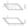
- FIGS. 7A and 7B are partially schematic isometric views of sacrificial sheets used to manufacture heat storage devices in accordance with embodiments of the presently disclosed technology.
- FIGS. 8A and 8B are partially schematic isometric views of a heat storage device in accordance with an embodiment of the presently disclosed technology.
- FIG. 9 is a schematic illustration of an arrangement of heat storage devices in accordance with an embodiment of the presently disclosed technology.
- Heat storage technology can be used in conjunction with solar energy systems in oil fields, electrical power generation, residential or industrial heating, and other uses.
- Embodiments of the present technology can be used to store excess energy at, for example, periods of high insolation, and also for supplementing production of steam at, for example, periods of low insolation.
- a person skilled in the relevant art will also understand that the technology may have additional embodiments, and that the technology may be practiced without several of the details of the embodiments described below with reference to FIGS. 4A-9 .
- the present technology uses thin members (e.g., thin plates) that are spaced closely together.
- the relatively thin members e.g., thin concrete plates
- the thin plates can store larger amounts of heat per unit weight, with the entire cross-section of the plates being at or close to isothermal conditions.
- Such plates can store and release heat faster because the final temperature gradient is established faster for a thin plate than for a thick plate made of the same material.
- the relatively thin, closely spaced plates have a relatively large area for heat exchange, resulting in a faster heat storage/release process.
- the disclosed methods and systems control the flow of the working fluid (e.g., a thermal oil) to be within a generally laminar flow regime, which is beneficial because the pressure drops in the laminar flow regime are smaller than those associated with turbulent flow regimes.
- conventional technologies rely on turbulent flows that result in higher coefficients of heat transfer (generally a desirable outcome), but at the cost of significantly higher pressure drops in the system.
- the laminar flow is facilitated by generally small distances between the adjacent plates and, at least in some embodiments, by controllers that limit the flow rate of the working fluid in the spaces between the adjacent plates.
- the potential downside of the lower heat transfer coefficient of the laminar flow is more than offset by the benefit of the lower pressure drops in the system.
- the thin plates can be manufactured at the installation site.
- a sacrificial material e.g., wax sheets
- concrete can be added into the mold.
- the sacrificial material can be removed (e.g., by melting).
- Manufacturing at the installation site reduces the transportation costs for the generally large and heavy heat storage devices.
- the sacrificial material can have apertures that enable interconnections between the concrete plates in the mold.
- the interconnected concrete plates can have (1) improved crack resistance due to additional structural strength of the connections between the plates, and/or (2) improved heat transfer due to the additional heat transfer area that the connections create in the flow of working fluid.
- Computer- or controller-executable instructions may take the form of computer- or controller-executable instructions, including routines executed by a programmable computer or controller.
- the technology can be embodied in a special-purpose computer, controller or data processor that is specifically programmed, configured or constructed to perform one or more of the computer-executable instructions described below.
- the terms “computer” and “controller” as generally used herein refer to any data processor and can include Internet appliances and hand-held devices (including palm-top computers, wearable computers, cellular or mobile phones, multi-processor systems, processor-based or programmable consumer electronics, network computers, mini computers and the like). Information handled by these computers can be presented at any suitable display medium, including a CRT display or LCD.
- the technology can also be practiced in distributed environments, where tasks or modules are performed by remote processing devices that are linked through a communications network.
- program modules or subroutines may be located in local and remote memory storage devices.
- aspects of the technology described below may be stored or distributed on computer-readable media, including magnetic or optically readable or removable computer disks, as well as distributed electronically over networks. Data structures and transmissions of data particular to aspects of the technology are also encompassed within the scope of the embodiments of the technology.
- FIG. 4A is a partially schematic cross-sectional view of a heat storage device 400 configured in accordance with an embodiment of the presently disclosed technology.
- the heat storage device 400 can include plates 431 (e.g., concrete plates) spaced apart and arranged in a housing 410 , an inlet pipe 413 connected to an inlet manifold 414 , and an outlet pipe 423 connected to an outlet manifold 424 .
- the plates 431 can be generally parallel and equidistant.
- a flow (indicated by a flow arrow 411 ) of the working fluid WF e.g., thermal oil
- WF working fluid
- the inlet manifold 414 has a larger cross section than that of the inlet pipe 413 . Therefore, as the working fluid WF enters the inlet manifold 414 , the velocity of the working fluid WF decreases and the pressure increases, resulting in a more uniform discharge of the working fluid through openings 412 spaced along the manifold 414 . As a result, the flow of the working fluid leaving the manifold 414 and approaching the plates 431 can also be more uniform.
- Channels 441 between the adjacent plates 431 can be sized to facilitate a predominantly laminar flow in the channels.
- the velocity of the working fluid and spacing between the plates 431 can be selected such that the Reynolds number (i.e., [velocity of the fluid] ⁇ [characteristic dimension of the flow passage]/[kinematic viscosity of the fluid]) is smaller than 2,000-5,000.
- the term “predominantly laminar” in this disclosure encompasses flows that may be turbulent or separated in some regions, e.g., close to the outer edges of the plates 431 , but are mostly laminar between the plates 431 .
- the spacing between the adjacent plates 431 i.e., the width of the channels 441
- the spacing between the adjacent plates 431 can be 1-2 mm.
- Such a spacing between the plates can also prevent an excessively low Reynolds number (e.g., less than about 3), where the viscous forces would dominate the flow and the flow between the plates 431 would be too slow.
- the predominantly laminar flow in the flow channels 441 can result in relatively low pressure drops within the heat storage device 400 .
- the thermal performance of the heat storage device 400 can be less sensitive to imperfections and nonuniformities in the size/shape of the channels 441 . That is, the velocity of the working fluid varies with the nonuniformities in the size/shape of the channels 441 , but these variations are generally less pronounced for laminar flow than for turbulent flow. Since the heat transfer to/from the plates 431 is a function of the velocity of the working fluid, the variations in in the heat transfer to/from the plates 441 will also be smaller as a result of the laminar flow in the channels 441 .
- the working fluid WF can enter the outlet manifold 424 through openings 422 .
- a relatively large diameter of the outlet manifold 424 reduces the velocity of the working fluid therefore increasing the uniformity of the flow across the heat storage device 400 .
- the working fluid WF can leave the heat storage 400 through the outlet pipe 423 as indicated by a flow arrow 421 , and can flow back to the solar heating system.
- the plates 431 can be relatively thin.
- the thickness of an individual plate 431 can be 10-20 or 20-30 mm.
- the relatively thin plates 431 produce a relatively large overall plate surface area for a given volume of the heat storage device 400 . Since heat is transferred between the working fluid WF and the plates 431 through the surface area of the plates 431 , a large total surface area of the plates 431 (relative to their volume) improves the transfer of heat into and out of the plates. This improved heat transfer can, for example, reduce the time to fully warm up or cool down plates 431 , thereby increasing the thermal efficiency of the heat storage device 400 .
- the temperature gradients in the thickness direction of the plates 431 are expected to be more uniform from one plate to another than for thick plates.
- the temperature gradients are expected to be shallower, allowing the thin plates to reach equilibrium more quickly than would the thick plates.
- the plates may be designed to have temperature distribution in the direction of the thickness of the plate within +/ ⁇ 5% or +/ ⁇ 1% of the average temperature in the direction of thickness at a given height of the plate (i.e., the temperature being within 5% or 1% of the isothermal condition in the direction of the thickness).
- the temperature distributions can be different, for example, the temperature distribution can be within +/ ⁇ 10% of the average temperature in the direction of the thickness of the plate.
- the working fluid WF can withstand relatively high temperatures (e.g., 300° C. or higher) without being pressurized, so as to transfer a large amount of energy to the plates 431 .
- the working fluid WF can be a molten salt capable of operating at even higher temperatures (e.g., 500° C. or higher).
- An optional coating, cladding or other encapsulant or enclosure can provide insulation around all or a portion of the heat storage device 400 .
- the insulation can include an air barrier, woven insulation, blown insulation, a ceramic barrier, and/or another suitable configurations.
- FIGS. 4B and 4C are partially schematic views of the plates of a heat storage device 400 configured in accordance with an embodiment of the presently disclosed technology. Collectively, FIGS. 4B and 4C illustrate balancing the flow of the working fluid through the channels 441 .
- the direction of the flow of the working fluid can be downward when the working fluid transfers heat to the plates 431 (e.g., when the insolation is relatively high), and upward when the plates 431 transfer heat to the working fluid (e.g., when the insolation is relatively low).
- the direction of the flow in FIG. 4B is from the top to the bottom, which can be representative of the plates 431 being heated by the working fluid (e.g., the working fluid is warmer than the plates 431 ).
- the direction of the flow in FIG. 4C is from the bottom to the top, that is the plates 431 can be cooled down by the working fluid (e.g., the working fluid is colder than the plates 431 .)
- the direction of the gravitational force is from the top to the bottom in both FIGS. 4B and 4C .
- the channels 441 can have a non-uniform width due to, for example, manufacturing errors or tolerances.
- the leftmost channels have width W 1 that is larger than the width W 2 of the rightmost channels.
- relatively wide channels having width W 1 would result in a relatively larger working fluid velocity U 1 due to smaller pressure drops associated with the wider channels.
- relatively narrow channels having width W 2 would result in a relatively smaller working fluid velocity U 2 .
- Such a non-uniformity in the working fluid velocity may be undesirable because, for example, some plates 431 would be heated/cooled too fast or too slow in comparison with the other plates 431 .
- a plate 431 that is adjacent to a wide channel may be heated faster than the rest of the plates in the thermal storage 400 , leading to a flow of the warm working fluid through the wide channel that, at least for a part of the cycle, does not transfer heat from the working fluid to the plate (e.g., after the plate is fully warmed up).
- the undesirable non-uniformities in the working fluid flow/plate temperature can be at least partially offset as explained below.
- a channel with a larger width W 1 generally promotes a relatively larger working fluid velocity U 1
- a narrower channel width W 2 generally promotes a relatively smaller working fluid velocity U 2 .
- the heat transfer from the working fluid to the plates can be relatively fast, i.e., the plates reach the temperature of the working fluid relatively fast.
- the higher fluid velocity U 1 heats the vertical length of the plates in the channel (e.g., the leftmost plate) faster than the lower fluid velocity U 2 (e.g., the rightmost plate).
- the portion of the vertical length of the plates 431 at a relatively high temperature T H is larger for the plates of the wider channel W 1 than the corresponding portion T H for the plates of the narrower channel W 2 .
- the working fluid at a higher temperature also has a lower viscosity and lower density than the working fluid at a lower temperature. Therefore, an overall relatively warmer fluid in the channel W 1 has overall relatively smaller viscosity v 1 and smaller density p 1 in comparison to the viscosity and density p 2 for the (overall) relatively colder fluid in the channel W 2 .
- the lower viscosity v 1 corresponding to the working fluid in the channel W 1 further promotes faster velocity of the working fluid in comparison to the working fluid in the channel W 1 .
- the overall warmer fluid in the channel W 1 also experiences a higher buoyancy, which can at least partially counteract the higher velocity of the working fluid in the channel W 1 .
- the flow direction that the buoyancy promotes is from the bottom to the top, i.e., in the direction opposite from the direction of the gravitational force. Due to a relatively smaller density p 1 in the channel W 1 , the buoyancy effect will be more pronounced in the channel W 1 than in the channel W 2 . Therefore, in at least some embodiments of the present technology, the buoyancy of the working fluid in the channels 431 can make the flow in the channels having different widths (e.g., W 1 and W 2 ) at least substantially uniform.
- the flow of the working fluid in the two channels having different widths is from the bottom of the page to the top of the page, and is opposite from the direction of the gravitational force.
- the pressure drop coefficient for a wider channel is generally smaller than the pressure drop coefficient for a corresponding narrow channel, thus generally promoting a higher working flow velocity in the wider channel.
- the working fluid entering the channels can be colder than the plates 431 , therefore heat is transferred from the plates 431 to the working fluid.
- cooling the plates 431 with a relatively faster flow velocity U 1 in the wide channel W 1 generally results in a longer vertical length of the plates 431 being at a relatively cold temperature T C .
- a relatively slower flow velocity U 2 in the narrow channel W 2 results in a shorter length of the plates 431 being at a relatively cold temperature T C .
- an average density p 1 of the working fluid in the wider channel W 1 is higher (due to the overall lower temperature of the working fluid) than the corresponding average density p 2 of the working fluid in the more narrow channel W 2 (due to the overall higher temperature of the working fluid).
- the relatively higher density p 1 results in a relatively higher pressure head in the wider channel W 1
- the relatively lower density p 2 results in a relatively lower pressure head in the narrower channel W 2 .
- the higher pressure head in the wider channel W 1 tends to reduce the working fluid velocity U 1 in the wider channel
- the lower pressure head in the narrower channel W 2 tends to promote (increase) the working fluid velocity U 2 in the narrower channel.
- the differences in the pressure heads of the wider channel W 1 and narrow channel W 2 promote a generally uniform flow (or at least a more uniform flow) within the channels having different widths.
- FIGS. 5A and 5B are partially schematic views of an arrangement of plates for a heat storage unit in accordance with an embodiment of the presently disclosed technology.
- FIG. 5A illustrates the plates 431 , e.g., concrete plates.
- FIG. 5B schematically illustrates the expected thermal expansion of a plate 431 as it undergoes heating during normal use.
- the individual concrete plates 431 are 0.5-1.5 m deep (D), 2.5-5 m high (H) and 10-30 mm thick (d), and the plates can have other suitable dimensions in other embodiments.
- the working fluid WF enters the channels 441 between the adjacent plates 431 as indicated by the flow arrow 411 , and leaves as indicated by the flow arrows 421 .
- the working fluid WF flows inside the channels 441 primarily in the direction of the height H.
- the temperature of the plates 431 changes uniformly from T 1 to T 2 in the direction of the flow (with T 1 generally higher than T 2 when the insolation is high, and vice versa when the insolation is low).
- it is desirable that the velocity and temperature of the working fluid do not vary from one channel to another, or at least do not vary significantly, and for the individual plates 431 to have the same or comparable temperature profiles (e.g., the same or comparable temperature gradient from T 1 to T 2 ).
- a distance between the adjacent plates 431 i.e., the width W of the channels 441
- the width W of the channels 441 is generally same (aside from, e.g., manufacturing errors and tolerances) to promote the same flow rates in the channels 441 and the same temperature profiles in the plates 431 .
- FIG. 5B schematically illustrates an expected thermal expansion of a plate 431 in accordance with an embodiment of the presently disclosed technology.
- the widths of the channels 441 between neighboring plates 431 can be designed and formed to be generally constant.
- cracks that develop in the plate 431 e.g., due to thermal stresses or vibrations
- a section of the plate 431 may become offset from the principal plane of the plate therefore changing the effective width of the channel 441 .
- a crack 512 may separate a section of the plate 431 from the rest of the plate. Under some conditions, the separated section of the plate can move out of the principal plane of the plate (e.g., out of the plane of page in FIG.
- the present technology can include one or more preferred direction(s) for crack development, as explained below.
- an initial outline 520 of the unheated plate 431 is illustrated with a solid line.
- the working fluid travels downwardly in the channels 441 (in the direction of the height H), the working fluid heats the plate 431 .
- the upper portion of the plate achieves a higher temperature (T 1 ) than the temperature T 2 of the lower portion of the plate.
- the resulting outline of the plate 431 is illustrated (in an exaggerated manner for purposes of illustration) with a dashed line 521 , and indicates that the upper portion of the plate 431 has a depth D H that is larger than a depth D C at the lower portion of the plate.
- the difference between the depths D H and D C can promote diagonal cracks 511 that extend diagonally across the plate.
- Such diagonally extending cracks 511 in general do not promote separation of the sections of the plate out of the principal plane of the plate.
- the plate 431 may be purposely weakened (e.g., thinned), to create a preferred direction for a crack 510 to propagate (e.g., by shaping the wax sheet described below with reference to FIGS. 6A-6C ).
- the cracks 510 and 511 do not (or at least do not significantly) promote separation of the sections of the plate that could change the width of the channels for the working fluid. Therefore, even when the plate 431 includes cracks 510 and/or 511 , the channel width remains generally constant and the flow of the working fluid remains generally the same in the individual channels.
- FIG. 6A is a schematic view of a mold 600 a for manufacturing a heat storage device in accordance with an embodiment of the presently disclosed technology.
- FIG. 6B is a detailed view of a portion of the mold 600 a .
- FIGS. 6A and 6B are discussed together below.
- the mold 600 a can include a mold housing 610 that contains sacrificial sheets 641 (e.g., formed from a meltable wax) arranged at a spacing or pitch P.
- sacrificial sheets 641 e.g., formed from a meltable wax
- an arrangement of supporting structures for example grooves 611 , can maintain the sacrificial sheets 641 at a required spacing.
- clips or holders or other suitable devices may be used to hold the sacrificial sheets in place.
- a molding material 631 e.g., concrete
- the molding material 631 can be poured between the sacrificial sheets 641 such that an approximately similar amount of the molding material 631 flows into the spaces between the sacrificial sheets 641 .
- a pressure of the concrete on the two opposing sides of the sacrificial sheets 641 is similar, and the sacrificial sheets 641 generally maintain their initial position and shape during the molding process.
- the mold 600 a can be turned on its side such that the sacrificial sheets 641 are horizontal.
- the molding process can start by adding an amount of the molding material 631 to cast one plate 431 .
- a sacrificial sheet 641 can be placed over the already added molding material, followed by adding an amount of the molding material that is sufficient to cast another plate 431 .
- the process can then be repeated for the number of required plates 431 .
- the sacrificial sheets 641 can be removed by, for example, melting them at a sufficiently high temperature (e.g. when the sacrificial sheets are made of a meltable wax or other material.
- the sacrificial sheets may be removable by a chemical reaction that, for example, dissolves or gasifies the sacrificial sheets 641 .
- a depth D of the sacrificial sheets 641 generally corresponds to a depth D of the channels 441 .
- the plates 431 can be removed by, for example, disassembling the mold housing 610 .
- An advantage of embodiments of the present technology is that relatively thin plates 431 can be created without having to machine the concrete.
- the illustrated molding process can be performed at the site, resulting in reduced transportation costs and delays.
- FIG. 6C is a schematic view of a mold 600 b for manufacturing a heat storage device in accordance with an embodiment of the presently disclosed technology.
- the mold 600 b can include a mold housing 610 that contains sacrificial sheets 641 (e.g., formed from meltable wax or plastic).
- the sacrificial sheets 641 can be arranged generally horizontally, but do not need to be necessarily horizontal and can be generally wavy.
- the process for manufacturing the plates 631 can start with pouring concrete at the bottom of the mold housing 610 , followed by placing down a sacrificial sheet 641 (or pouring the material of the sacrificial sheet 641 ) over the concrete.
- an additional layer of concrete (or other plate material) can be poured, followed by an additional sacrificial sheet 641 , and the process continues.
- the sacrificial sheets 641 are removed by, for example, melting or chemical reaction.
- the resulting channels (where the sacrificial sheets 641 used to be) can have a generally constant width W. Therefore, for a flow of the working fluid in and out of the page, even though the channel may be wavy, the width W of the channel is essentially constant (other than for manufacturing or tolerance variations). In at least some embodiments, not having to produce flat plates may simplify the manufacturing process and/or make it more robust.
- FIGS. 7A-B are partially schematic isometric views of sacrificial sheets configured in accordance with embodiments of the presently disclosed technology.
- FIGS. 7A, 7B illustrate sacrificial sheets 712 a , 712 b , respectively, having a depth D S and a height H S that generally determine the depth/height of the corresponding channels of the heat storage device.
- the sacrificial sheet 712 a is generally solid.
- the molded plates have side surfaces that are generally flat and are not connected to the adjacent plates.
- the sacrificial sheet 712 b includes openings 710 that, during the molding process, allow a flow of the molding material through the openings 710 from a space occupied by one plate to a space occupied by an adjacent plate.
- the side surfaces of the adjacent plates in the mold can be connected by the mold material in the openings 710 .
- the connections between the adjacent plates remain in place.
- the connections can add structural strength and can reduce cracking of the otherwise relatively slender plates.
- the connections can provide an additional area for the heat exchange between the working fluid and the plates.
- the connections can maintain the designed spacing between plates, and therefore the widths of the flow channels between plates.
- the illustrated openings 710 are generally oval, but can have other shapes (e.g., slits oriented in the direction of flow) in other embodiments.
- FIG. 8A is a partially schematic isometric view of a heat storage device 800 configured in accordance with an embodiment of the presently disclosed technology.
- FIG. 8B is a detailed view of a portion of the heat storage device 800 .
- the illustrated heat storage device 800 includes several plates 431 arranged along a length L.
- the plates 431 have a thickness t, a depth D and a height H.
- the spaces between the adjacent plates corresponds to the width W of the channels 441 .
- a distance between the consecutive channels 441 is a pitch P.
- Flow arrows 411 , 421 indicate the direction of flow of the working fluid WF.
- the working fluid WF can flow through the channels 441 from the top to the bottom of the heat storage device 800 to transfer heat to/from the plates 431 .
- the working fluid WF leaves the heat storage device 800 at the bottom, as illustrated by the flow arrow 421 .
- FIG. 8B illustrates a portion of an arrangement of the plates 431 .
- a base plate 811 supports the plates 431 inside corresponding base grooves 812 .
- a width of the base grooves 812 is generally the same as the thickness of the plates 431 . In other embodiments, the width of the base grooves can be larger than the thickness of the plates 431 .
- additional base plates 811 can support the plates 431 at, for example, corners of the plates 431 to maintain a generally vertical position of the plates 431 .
- a distance between the adjacent base grooves 812 can at least in part determine the width W of the channels 441 .
- the base plate 811 can be manufactured from the same material as the plates 431 (e.g., from concrete) for lower cost and shorter lead times.
- a single heat storage device 800 may not have sufficient capacity and, therefore, multiple heat storage devices 800 may be arranged together, as explained below with reference to FIG. 9 .
- FIG. 9 is a schematic illustration of an arrangement 900 of multiple heat storage devices in accordance with an embodiment of the presently disclosed technology.
- the illustrated embodiment includes three heat storage devices (indicated as first-third devices 900 a - 900 c ), and in other embodiments, the arrangement can include other numbers of heat storage devices, depending (for example) on the overall heat storage capacity needs of a particular application.
- the working fluid when the solar insolation is relatively high, the working fluid generally (e.g., for most of the time) transfers heat to the plates inside the heat storage. Conversely, when the solar insolation is relatively low, the plates generally transfer heat to the working fluid.
- the working fluid WF can enter the first heat storage 900 a as indicated by flow arrow 411 a at the top of the unit, and leave as indicated by flow arrow 421 a at the bottom of the unit when the working fluid WF transfers heat to the plates of the heat storage 900 a .
- the heat storage devices 900 a - 900 c are arranged in series, e.g., the working fluid WF flows from the outlet of the first heat storage device 900 a to the inlet of the second heat storage device 900 b (arrow 411 b ), and, after exiting the second heat storage device 900 b (arrow 421 b ), further to the inlet of the third heat storage device 900 c (arrow 411 c ), and from the exit of the third heat storage device 900 c (arrow 421 c ).
- Such an arrangement of the flow of the working fluid WF through the heat storage devices 900 a - 900 c can correspond to a relatively high insolation.
- the flow of the working fluid WF can enter the first heat storage device 900 a at the bottom, flow through the first heat storage device 900 a while receiving heat from the plates in the first heat storage device 900 a , exit the first heat storage device 900 a at the top, and enter at the bottom of the second heat storage device 900 b , and go on to the third heat storage device 900 c.
- the arrangement 900 is a sample arrangement of heat storage devices, and other field-specific serial/parallel arrangements can be used in other embodiments. Furthermore, the three heat storage devices are illustrated as having generally the same shape and size, but the heat storage devices can have different shapes and/or sizes in other embodiments.
- the arrangement 900 can include valves positioned to regulate amount of the working fluid flowing through any one or combination of heat storage devices.
- the valves can be controlled by a controller 901 to limit or stop the flow of the working fluid to some of the heat storage devices, depending on, for example, insolation and required production of the steam in the field.
- the controller 901 can control valves 910 - 913 to maintain a laminar or generally laminar flow through the heat storage devices of the arrangement 900 , or at least through some heat storage devices.
- the arrangement can include other numbers and/or locations of the valves.
- the controller 901 may include a computer-readable medium (e.g., hard drive, programmable memory, optical disk, non-volatile memory drive, etc.) that carries computer-based instructions for directing the operation of the valves 910 - 913 and/or other components of the assembly and/or larger system.
- a computer-readable medium e.g., hard drive, programmable memory, optical disk, non-volatile memory drive, etc.
- the systems described above can include trough-shaped, mirror-based solar concentrators.
- the solar collection systems can include other types of solar collectors, including, but not limited to point-source collectors, power-tower arrangements, dish-shaped collectors, and/or Fresnel collectors.
- Particular embodiments of the systems described above were described in the context of water as a working fluid. In other embodiments, the systems can operate in generally the same manner, using other types of working fluids, or combinations of different working fluids.
Landscapes
- Engineering & Computer Science (AREA)
- Mechanical Engineering (AREA)
- Physics & Mathematics (AREA)
- General Engineering & Computer Science (AREA)
- Chemical & Material Sciences (AREA)
- Thermal Sciences (AREA)
- Ceramic Engineering (AREA)
- Sustainable Energy (AREA)
- Life Sciences & Earth Sciences (AREA)
- Manufacturing & Machinery (AREA)
- Sustainable Development (AREA)
- Combustion & Propulsion (AREA)
- Building Environments (AREA)
- Engine Equipment That Uses Special Cycles (AREA)
- Heat-Exchange Devices With Radiators And Conduit Assemblies (AREA)
Abstract
Description
Claims (23)
Priority Applications (1)
| Application Number | Priority Date | Filing Date | Title |
|---|---|---|---|
| US14/920,700 US10288322B2 (en) | 2014-10-23 | 2015-10-22 | Heat storage devices for solar steam generation, and associated systems and methods |
Applications Claiming Priority (2)
| Application Number | Priority Date | Filing Date | Title |
|---|---|---|---|
| US201462067806P | 2014-10-23 | 2014-10-23 | |
| US14/920,700 US10288322B2 (en) | 2014-10-23 | 2015-10-22 | Heat storage devices for solar steam generation, and associated systems and methods |
Publications (2)
| Publication Number | Publication Date |
|---|---|
| US20160116188A1 US20160116188A1 (en) | 2016-04-28 |
| US10288322B2 true US10288322B2 (en) | 2019-05-14 |
Family
ID=55761583
Family Applications (1)
| Application Number | Title | Priority Date | Filing Date |
|---|---|---|---|
| US14/920,700 Active 2036-12-17 US10288322B2 (en) | 2014-10-23 | 2015-10-22 | Heat storage devices for solar steam generation, and associated systems and methods |
Country Status (5)
| Country | Link |
|---|---|
| US (1) | US10288322B2 (en) |
| EP (1) | EP3183512A4 (en) |
| CN (1) | CN107003033A (en) |
| AU (1) | AU2015335752A1 (en) |
| WO (1) | WO2016065191A1 (en) |
Families Citing this family (17)
| Publication number | Priority date | Publication date | Assignee | Title |
|---|---|---|---|---|
| WO2012006288A2 (en) | 2010-07-05 | 2012-01-12 | Glasspoint Solar, Inc. | Subsurface thermal energy storage of heat generated by concentrating solar power |
| US10197312B2 (en) * | 2014-08-26 | 2019-02-05 | Mahle International Gmbh | Heat exchanger with reduced length distributor tube |
| EP3390906A1 (en) | 2016-02-01 | 2018-10-24 | Glasspoint Solar, Inc. | Separators and mixers for delivering controlled-quality solar-generated steam over long distances for enhanced oil recovery, and associated systems and methods |
| US11692778B2 (en) | 2017-06-21 | 2023-07-04 | Westinghouse Electric Company Llc | Energy storage device |
| WO2018236489A1 (en) * | 2017-06-21 | 2018-12-27 | Westinghouse Electric Company Llc | Energy storage device |
| CN107289805A (en) * | 2017-07-25 | 2017-10-24 | 大连美天新能源科技有限公司 | The outdoor hot energy storage device of Large Copacity |
| US12291982B2 (en) | 2020-11-30 | 2025-05-06 | Rondo Energy, Inc. | Thermal energy storage systems for use in material processing |
| JP7645867B2 (en) * | 2019-08-22 | 2025-03-14 | ウェスティングハウス エレクトリック カンパニー エルエルシー | Energy Storage Device |
| US11913362B2 (en) | 2020-11-30 | 2024-02-27 | Rondo Energy, Inc. | Thermal energy storage system coupled with steam cracking system |
| US12359591B1 (en) | 2020-11-30 | 2025-07-15 | Rondo Energy, Inc. | Thermal energy storage systems for repowering existing power plants for improving efficiency and safety |
| US11913361B2 (en) | 2020-11-30 | 2024-02-27 | Rondo Energy, Inc. | Energy storage system and alumina calcination applications |
| IL321345A (en) | 2020-11-30 | 2025-08-01 | Rondo Energy Inc | Energy storage system and applications |
| US12018596B2 (en) | 2020-11-30 | 2024-06-25 | Rondo Energy, Inc. | Thermal energy storage system coupled with thermal power cycle systems |
| US12146424B2 (en) | 2020-11-30 | 2024-11-19 | Rondo Energy, Inc. | Thermal energy storage system coupled with a solid oxide electrolysis system |
| IT202200016569A1 (en) * | 2022-08-03 | 2024-02-03 | Energy Dome S P A | Thermal energy storage device and energy transformation and storage system |
| WO2024215951A1 (en) | 2023-04-14 | 2024-10-17 | Rondo Energy, Inc. | Thermal energy storage blocks and associated support structures |
| WO2025226989A2 (en) | 2024-04-24 | 2025-10-30 | Rondo Energy, Inc. | Thermal energy storage system for simple and combined cycle power generation |
Citations (189)
| Publication number | Priority date | Publication date | Assignee | Title |
|---|---|---|---|---|
| US1240890A (en) | 1912-09-30 | 1917-09-25 | Frank Shuman | Sun-boiler. |
| US2217593A (en) | 1939-06-29 | 1940-10-08 | Robinson & Steinman | Bracing for suspension bridges |
| US2221919A (en) | 1938-08-23 | 1940-11-19 | Kenan Wilder | Bridge construction |
| US2859745A (en) | 1954-05-04 | 1958-11-11 | Brudersdorff Luis Von | Solar energy operated heaters |
| US3672572A (en) | 1970-07-27 | 1972-06-27 | Valmont Industries | Rough ground self-propelled sprinkling irrigation apparatus |
| US3847136A (en) | 1973-07-27 | 1974-11-12 | N Salvail | Solar water-heating systems |
| US3923039A (en) | 1975-02-07 | 1975-12-02 | Gerald Falbel | Solar energy heating system |
| US3962873A (en) | 1974-05-20 | 1976-06-15 | Thermo Electron Corporation | Solar steam generator |
| US3991740A (en) | 1975-07-28 | 1976-11-16 | The United States Of America As Represented By The United States Energy Research And Development Administration | Sea shell solar collector |
| US3994279A (en) | 1975-07-24 | 1976-11-30 | The United States Of America As Represented By The United States Energy Research And Development Administration | Solar collector with improved thermal concentration |
| US3994341A (en) | 1975-10-30 | 1976-11-30 | Chevron Research Company | Recovering viscous petroleum from thick tar sand |
| US3996917A (en) | 1974-03-27 | 1976-12-14 | Malz Nominees Pty. Ltd. | Solar heating apparatus |
| US4003366A (en) | 1975-12-11 | 1977-01-18 | Lightfoot Daniel J | Solar heat collector module |
| US4015585A (en) | 1975-08-21 | 1977-04-05 | Arthur Fattor | Solar heating apparatus |
| US4078549A (en) | 1976-08-05 | 1978-03-14 | Mckeen Thomas Ray | Solar energy collector |
| US4083155A (en) | 1977-03-14 | 1978-04-11 | Lampert Albert J | Thermally insulated enclosure |
| US4088116A (en) | 1976-01-06 | 1978-05-09 | Jose Pastor | Radiant energy collector |
| US4095369A (en) | 1976-03-24 | 1978-06-20 | Mario Posnansky | Installation for cultivating plant cultures |
| US4108154A (en) | 1976-11-22 | 1978-08-22 | Homer Van Dyke | Solar energy collection system |
| US4122832A (en) | 1976-05-14 | 1978-10-31 | Ladislav Hirschsohn | Solar collector |
| US4124277A (en) | 1977-02-16 | 1978-11-07 | Martin Marietta Corporation | Parabolic mirror construction |
| US4143642A (en) | 1976-09-24 | 1979-03-13 | Vapor Corporation | High temperature thermal storage system utilizing solar energy units |
| US4149523A (en) | 1976-06-03 | 1979-04-17 | Bertin & Cie | Solar energy collector system with cylindro-parabolic mirror |
| US4159712A (en) | 1977-10-20 | 1979-07-03 | Legg Howard W | Solar energy conversion unit |
| US4174752A (en) | 1978-01-24 | 1979-11-20 | Dale Fuqua | Secondary recovery method and system for oil wells using solar energy |
| US4184482A (en) | 1978-09-29 | 1980-01-22 | Cohen Elie | Solar energy collecting system |
| US4202322A (en) | 1977-05-11 | 1980-05-13 | Del Manufacturing Company | Solar energy collector and heat exchanger |
| US4209222A (en) | 1977-05-03 | 1980-06-24 | Bernardo Raimann | Installation for utilizing solar energy with wavelength selective reflector |
| US4219008A (en) | 1978-09-06 | 1980-08-26 | John Schultz | Method and apparatus for solar heating and shading |
| USRE30407E (en) | 1979-01-15 | 1980-09-23 | Solar heat collector module | |
| US4230095A (en) | 1978-05-26 | 1980-10-28 | The United States Of America As Represented By The United States Department Of Energy | Ideal light concentrators with reflector gaps |
| US4237864A (en) | 1978-05-15 | 1980-12-09 | Barry Kravitz | Focusing solar collector |
| US4249340A (en) | 1978-12-07 | 1981-02-10 | Environmental Research Institute Of Michigan | Solar energy collector |
| US4258696A (en) | 1978-04-05 | 1981-03-31 | Johnson Controls, Inc. | Passive thermal energy phase change storage apparatus |
| US4262653A (en) | 1979-05-01 | 1981-04-21 | Neha International | Solar energy heat storage and transfer system |
| US4263893A (en) | 1978-10-03 | 1981-04-28 | Consuntrator, Inc. | Solar energy collector construction |
| JPS5685508A (en) | 1979-12-14 | 1981-07-11 | Nissan Motor Co Ltd | Power generator for propulsion |
| US4280480A (en) | 1980-03-17 | 1981-07-28 | Raposo Sulpicio B | Solar heating plant |
| US4282394A (en) | 1979-10-24 | 1981-08-04 | The Boeing Company | Underwing reflector solar array |
| US4287880A (en) | 1979-11-13 | 1981-09-08 | Geppert John M | Solar collector |
| US4290419A (en) | 1979-06-28 | 1981-09-22 | Rabedeaux Richard W | Multi systems solar collector |
| US4296739A (en) | 1980-06-23 | 1981-10-27 | Bolding Gaines H | Solar collector using cotton seed oil to transfer heat to heavy oil wells |
| EP0041725A1 (en) | 1980-06-10 | 1981-12-16 | Iduso Gesellschaft zur Förderung und Verwertung kreativer Ideen mbH | Method and apparatus for the manufacture of flashless hollow bodies closed on all sides, made in one piece of cold mouldable and settable or setting material |
| US4314604A (en) | 1978-09-23 | 1982-02-09 | Josef Koller | Apparatus for the segregation of worn-out cleaning bodies |
| US4318394A (en) | 1980-01-11 | 1982-03-09 | Alexander William C | Solar energy concentrator |
| US4333447A (en) | 1980-06-04 | 1982-06-08 | Corning Glass Works | Solar receiver tube support |
| US4343533A (en) | 1980-12-31 | 1982-08-10 | Dow Corning Corporation | Solar radiation reflector with a cellulosic substrate and method of making |
| US4371623A (en) | 1981-02-09 | 1983-02-01 | William N. Durkin | Solar still |
| US4372386A (en) | 1981-02-20 | 1983-02-08 | Rhoades C A | Steam injection method and apparatus for recovery of oil |
| US4386600A (en) | 1981-02-23 | 1983-06-07 | The Budd Company | Support structure for supporting a plurality of aligned solar reflector panels |
| US4392531A (en) | 1981-10-09 | 1983-07-12 | Ippolito Joe J | Earth storage structural energy system and process for constructing a thermal storage well |
| US4410156A (en) | 1977-10-08 | 1983-10-18 | Mannesmann Aktiengesellschaft | Suspension of pipes or tubes undergoing thermal expansion |
| US4423719A (en) | 1980-04-03 | 1984-01-03 | Solar Kinetics, Inc. | Parabolic trough solar collector |
| US4445499A (en) | 1976-11-01 | 1984-05-01 | Sunstore Kommanditbolag | Ground-storage of heat such as solar heat |
| US4452233A (en) * | 1982-03-04 | 1984-06-05 | Goodman Jr Maurice | Solar energy collector |
| US4452229A (en) | 1981-11-13 | 1984-06-05 | Kim Powers | Thermal heat storage and cooling system |
| US4462390A (en) | 1981-10-16 | 1984-07-31 | Holdridge Robert B | Modular solar greenhouse with elevated overhead heat storage material and movable insulation barriers and method and system for solar heating of attached living space using thermostat-controlled air circulation for harvesting heat |
| US4484568A (en) | 1981-08-31 | 1984-11-27 | Solar Kinetics, Inc. | Overheat emergency outfocus mechanism for solar energy collector |
| US4490926A (en) | 1982-11-26 | 1985-01-01 | Scott Stokes | Solar drying device and method for drying |
| WO1985001339A1 (en) | 1983-09-13 | 1985-03-28 | Silkok-Peltzer Gmbh & Co. Kg | Method for manufacturing a heat exchanger |
| US4513733A (en) | 1982-11-12 | 1985-04-30 | The Babcock & Wilcox Company | Oil field steam production and use |
| US4577679A (en) | 1978-10-25 | 1986-03-25 | Hibshman Henry J | Storage systems for heat or cold including aquifers |
| US4597377A (en) | 1984-10-09 | 1986-07-01 | Melamed Alan M | Solar reflector system |
| US4628142A (en) | 1984-03-19 | 1986-12-09 | Kabushiki Kaisha Toshiba | Solar tracking mechanisms |
| US4727854A (en) | 1986-05-08 | 1988-03-01 | Johnson Arthur C W | High efficiency infrared radiant energy heating system and reflector therefor |
| US4741161A (en) | 1985-12-09 | 1988-05-03 | Alfred Teves Gmbh | Braking pressure generator for a hydraulic brake system for automotive vehicles |
| CN2050918U (en) | 1989-01-26 | 1990-01-10 | 陈经文 | Sealing type telescopic device for conduit |
| US5018576A (en) | 1989-08-16 | 1991-05-28 | The Regents Of The University Of California | Process for in situ decontamination of subsurface soil and groundwater |
| US5048507A (en) | 1989-02-07 | 1991-09-17 | Ridett Alan H | Endothermic building |
| US5058675A (en) | 1990-10-29 | 1991-10-22 | Travis Elmer E | Method and apparatus for the destructive distillation of kerogen in situ |
| US5103524A (en) | 1989-02-08 | 1992-04-14 | Barry Bros. Specialised Services Pty. Ltd. | Apparatus for cleaning the inner surfaces of tubes in operating multi-tube heat transfer devices |
| EP0506568A1 (en) | 1991-03-28 | 1992-09-30 | Heliosynthese S.A. | Photobioreactor with a device for the automatic and continuous cleaning of the pipeline in the solar receptor of the photobioreactor |
| US5191876A (en) | 1992-03-04 | 1993-03-09 | Atchley Curtis L | Rotatable solar collection system |
| US5258101A (en) | 1990-03-14 | 1993-11-02 | Wayne Technology Corp. | Pyrolytic conversion system |
| FR2696753A1 (en) | 1992-10-13 | 1994-04-15 | Inst Fs Rech Expl Mer | Device for cleaning the pipelines of a photobioreactor and photobioreactor provided with this device. |
| US5344496A (en) | 1992-11-16 | 1994-09-06 | General Dynamics Corporation, Space Systems Division | Lightweight solar concentrator cell array |
| US5347402A (en) | 1992-08-12 | 1994-09-13 | Porter Arbogast | Multiple mirror assembly for solar collector |
| US5520747A (en) | 1994-05-02 | 1996-05-28 | Astro Aerospace Corporation | Foldable low concentration solar array |
| US5524610A (en) | 1995-03-20 | 1996-06-11 | Clark; John D. | Solar powered/multiple fuel cooking device |
| US5699785A (en) | 1996-09-26 | 1997-12-23 | Sparkman; Scott | Solar energy collector |
| US5851309A (en) | 1996-04-26 | 1998-12-22 | Kousa; Paavo | Directing and concentrating solar energy collectors |
| US5941238A (en) | 1997-02-25 | 1999-08-24 | Ada Tracy | Heat storage vessels for use with heat pumps and solar panels |
| US5954046A (en) | 1994-05-19 | 1999-09-21 | Resaro Ab | Heating and ventilation system for a building |
| US6017002A (en) | 1997-07-21 | 2000-01-25 | Hughes Electronics Corporation | Thin-film solar reflectors deployable from an edge-stowed configuration |
| US6129844A (en) | 1996-11-26 | 2000-10-10 | Dobelmann; Jan Kai | Waste water purification process |
| JP2001082104A (en) | 1999-09-17 | 2001-03-27 | Takahashi Kikan:Kk | Steam supply system |
| US6220339B1 (en) | 1995-09-12 | 2001-04-24 | Edmond D. Krecke | Energy system for buildings |
| US6233914B1 (en) | 1997-07-31 | 2001-05-22 | Ormat Industries Ltd. | Method of an apparatus for producing power having a solar reformer and a steam generator which generate fuel for a power plant |
| US20010008144A1 (en) | 1998-02-26 | 2001-07-19 | Tsuyoshi Uematsu | Photovoltalic device, photovoltaic module and establishing method of photovoltaic system |
| US6363928B1 (en) | 2000-04-04 | 2002-04-02 | Alternative Energy Group, Inc. | Solar collection system |
| US20020108745A1 (en) | 1999-01-19 | 2002-08-15 | Shigeaki Kimura | Cogeneration system with a heat reservoir |
| US6485152B2 (en) | 2000-05-05 | 2002-11-26 | Doug Wood | Matrix solar dish |
| US6508850B1 (en) | 2000-11-16 | 2003-01-21 | Igor K. Kotliar | Clean air tent system |
| US6547210B1 (en) | 2000-02-17 | 2003-04-15 | Wright Medical Technology, Inc. | Sacrificial insert for injection molding |
| US20030080604A1 (en) | 2001-04-24 | 2003-05-01 | Vinegar Harold J. | In situ thermal processing and inhibiting migration of fluids into or out of an in situ oil shale formation |
| EP0988493B1 (en) | 1997-06-13 | 2003-08-13 | Vattenfall Ab | Method of optimisation of a sun panel |
| US20030188477A1 (en) | 2000-06-15 | 2003-10-09 | Dov Pasternak | Environmentally friendly conditioning system particularly for a greenhouse |
| US20040004303A1 (en) | 2002-07-03 | 2004-01-08 | Therics, Inc. | Apparatus, systems and methods for use in three-dimensional printing |
| US20040055594A1 (en) | 2002-09-20 | 2004-03-25 | Hochberg Eric B. | Lightweight, low-cost solar energy collector |
| DE102004013590A1 (en) | 2004-03-19 | 2005-10-13 | Deutsches Zentrum für Luft- und Raumfahrt e.V. | Solar heat collector has array of mirrors suspended by wires that adjust angle of reflection to joint receiving panel |
| US20060048770A1 (en) | 2004-09-08 | 2006-03-09 | Sovani Meksvanh | Solar augmented geothermal energy |
| US7028685B1 (en) | 1998-03-09 | 2006-04-18 | Edmond Krecke | Air conditioning system for buildings and air-conditioned building, especially a zero energy house |
| US7055519B2 (en) | 2003-12-10 | 2006-06-06 | United Technologies Corporation | Solar collector and method |
| US20060124360A1 (en) | 2004-11-19 | 2006-06-15 | Halliburton Energy Services, Inc. | Methods and apparatus for drilling, completing and configuring U-tube boreholes |
| DE202005021000U1 (en) | 2005-12-21 | 2007-01-11 | Novatec Biosol Ag | Hot pipe support cradle for solar-powered heliostat power generator gas roller bearings in contact with the pipe |
| US20070056726A1 (en) | 2005-09-14 | 2007-03-15 | Shurtleff James K | Apparatus, system, and method for in-situ extraction of oil from oil shale |
| US7234314B1 (en) | 2003-01-14 | 2007-06-26 | Earth To Air Systems, Llc | Geothermal heating and cooling system with solar heating |
| CN2926930Y (en) | 2006-07-14 | 2007-07-25 | 于元亮 | Automatic Tracking Focus Stationary Solar Cooker |
| US20070209365A1 (en) | 2004-03-12 | 2007-09-13 | Larkden Pty Limited | Method And Apparatus For Storing Heat Energy |
| CN200958464Y (en) | 2006-04-29 | 2007-10-10 | 张嘉明 | Thermotropic telescopic apparatus |
| WO2007146183A2 (en) | 2006-06-08 | 2007-12-21 | Sopogy, Inc. | Apparatus and methods for concentrating solar power |
| US7337843B2 (en) | 2006-02-13 | 2008-03-04 | Mecham Travis W | Solar blackbody waveguide for solar assisted oil recovery applications |
| KR20080024309A (en) | 2006-09-13 | 2008-03-18 | 미래에너지기술(주) | Solar Focused Generator |
| US20080066736A1 (en) | 2006-07-25 | 2008-03-20 | Yanong Zhu | Method and apparatus for solar energy storage system using gas and rock |
| CN201059795Y (en) | 2007-06-14 | 2008-05-14 | 东莞市康达机电工程有限公司 | Medium and high temperature concentrating solar heat collection system |
| US20080163864A1 (en) | 2006-11-22 | 2008-07-10 | Theodore Edward Larson | Adjustable solar collector and method of use |
| US20080216822A1 (en) | 2007-03-06 | 2008-09-11 | Lazzara Samuel P | Solar engery system |
| CN101270675A (en) | 2008-04-24 | 2008-09-24 | 华北电力大学 | Hybrid thermal power generation system of solar and coal-fired units |
| US20080236227A1 (en) | 2007-04-02 | 2008-10-02 | Flynn Timothy M | Dry land erosion control using photosynthetic nitrogen-fixing microorganisms |
| CN101280966A (en) | 2007-04-03 | 2008-10-08 | 庄绍林 | Sunlight-assisted thermal power plant |
| WO2008131175A1 (en) | 2007-04-20 | 2008-10-30 | Shell Oil Company | Molten salt as a heat transfer fluid for heating a subsurface formation |
| US20080308094A1 (en) | 2006-02-03 | 2008-12-18 | Johnston Glen | Trough reflectors for solar energy collectors |
| WO2008153922A1 (en) | 2007-06-06 | 2008-12-18 | Ausra, Inc. | Integrated solar energy receiver-storage unit |
| WO2009002772A2 (en) | 2007-06-22 | 2008-12-31 | Algaedyne Corportion | Bioreactor |
| CN101354191A (en) | 2008-09-26 | 2009-01-28 | 南京工业大学 | Solar cascade development heat utilization system |
| CN101363958A (en) | 2008-08-27 | 2009-02-11 | 吴砺 | Solar gathering structure and use thereof |
| US20090056698A1 (en) | 2007-09-05 | 2009-03-05 | Skyline Solar, Inc. | Solar collector framework |
| US20090056699A1 (en) | 2007-08-27 | 2009-03-05 | Mills David R | Linear fresnel solar arrays and receievers therefor |
| US20090056704A1 (en) | 2007-08-29 | 2009-03-05 | Xeliox S.R.L. | Reflecting parabolic construction for solar heating systems |
| US20090056944A1 (en) | 2007-08-30 | 2009-03-05 | George Nitschke | Enhanced oil recovery system for use with a geopressured-geothermal conversion system |
| US20090199847A1 (en) | 2008-02-11 | 2009-08-13 | James Hawley | Earth based solar collector |
| WO2009105643A2 (en) | 2008-02-22 | 2009-08-27 | Dow Global Technologies Inc. | Heat storage devices |
| WO2009126875A2 (en) | 2008-04-10 | 2009-10-15 | C-3 International, Llc | Pig and method for applying prophylactic surface treatments |
| US20090260359A1 (en) | 2008-04-16 | 2009-10-22 | Alstom Technology Ltd. | Solar thermal power plant |
| US20090277440A1 (en) | 2008-05-12 | 2009-11-12 | Arizona Board Of Regents On Behalf Of University Of Arizona | Solar concentrator apparatus with large, multiple, co-axial dish reflectors |
| US20090294092A1 (en) | 2008-05-30 | 2009-12-03 | Bahl Carsten | Device and system for storing thermal energy |
| CN201359397Y (en) | 2009-01-04 | 2009-12-09 | 刘阳 | Solar energy concentrating device and building element employing same |
| US20090320830A1 (en) | 2008-06-27 | 2009-12-31 | The Boeing Company | Solar power device |
| US20100000733A1 (en) | 2008-07-03 | 2010-01-07 | Matteo Chiesa | Apparatus and Method for Energy-Efficient and Environmentally-friendly Recovery of Bitumen |
| US20100051016A1 (en) | 2008-08-27 | 2010-03-04 | Ammar Danny F | Modular fresnel solar energy collection system |
| US20100051021A1 (en) | 2007-03-30 | 2010-03-04 | Amaton Sa | Parabolic trough collector |
| WO2010032095A2 (en) | 2008-09-18 | 2010-03-25 | Kloben S.A.S. Di Turco Adelino Ec. | Non-tracking solar collector device |
| WO2010040957A2 (en) | 2008-10-09 | 2010-04-15 | Cabarbaye Andre | Optimal solar concentrator device and sensor comprising a plurality of such concentrator devices |
| WO2010043744A2 (en) | 2008-10-14 | 2010-04-22 | Iberdrola Ingeniería Y Construcción, S. A. U. | Improved structure applicable to parabolic-trough power collectors |
| DE102009036550A1 (en) | 2008-11-01 | 2010-05-06 | Deutsches Zentrum für Luft- und Raumfahrt e.V. (DLR) | Device and system for temporary storage of thermal energy |
| US7748137B2 (en) | 2007-07-15 | 2010-07-06 | Yin Wang | Wood-drying solar greenhouse |
| US20100175687A1 (en) | 2009-01-13 | 2010-07-15 | Hamilton Sundstrand Corporation | Catalyzed hot gas heating system for concentrated solar power generation systems |
| WO2010088632A2 (en) | 2009-02-02 | 2010-08-05 | Glasspoint Solar, Inc. | Concentrating solar power with glasshouses |
| US20100212894A1 (en) | 2009-02-20 | 2010-08-26 | Conocophillips Company | Steam generation for steam assisted oil recovery |
| US20100300431A1 (en) | 2009-05-26 | 2010-12-02 | Carrascosa Perez Marco Antonio | Radiation heat collection device |
| US7858875B2 (en) | 2005-09-29 | 2010-12-28 | Enfocus Engineering Corp. | Radiant energy conversion system |
| US20110017274A1 (en) | 2009-01-06 | 2011-01-27 | Zhong Huang | Large Tracking-Type Fresnel Lens Point-Focusing Solar System |
| US20110088686A1 (en) | 2002-09-20 | 2011-04-21 | Hochberg Eric B | Lightweight, low cost solar energy collector |
| WO2011053863A2 (en) | 2009-10-30 | 2011-05-05 | Areva Solar, Inc. | Dual fluid circuit system for generating a vaporous working fluid using solar energy |
| US20110126824A1 (en) | 2009-05-15 | 2011-06-02 | Areva Solar, Inc. | Systems and methods for producing steam using solar radiation |
| US7975686B2 (en) | 2007-04-05 | 2011-07-12 | Prueitt Melvin L | High leverage trough solar collector |
| US20110174935A1 (en) | 2010-01-21 | 2011-07-21 | Chalice Bingham | Swivel-coupling hanger assembly |
| US7992553B2 (en) | 2004-02-17 | 2011-08-09 | Areva Solar Pty Limited | Multi-tube solar collector structure |
| US20110203577A1 (en) | 2008-06-27 | 2011-08-25 | Elletiemme S.R.L. | Covering device for roof and the like |
| US20110240006A1 (en) | 2010-04-01 | 2011-10-06 | Linke Edward J | Solar Tracking System and Method |
| US8056555B2 (en) | 2006-04-12 | 2011-11-15 | Prueitt Melvin L | Thin film trough solar collector |
| US20110277470A1 (en) | 2008-11-05 | 2011-11-17 | Shay Benyaminy | Solar Thermal Power Plant and Dual-Purpose Pipe for Use Therewith |
| US20110291405A1 (en) | 2008-08-14 | 2011-12-01 | Senior Berghofer Gmbh | Connecting System for a Line Tube, Which Can Be Pivoted About a Rotation Axis, of a Solar-Thermal Installation |
| WO2012006258A2 (en) | 2010-07-05 | 2012-01-12 | Glasspoint Solar, Inc. | Oilfield application of solar energy collection |
| WO2012006257A2 (en) | 2010-07-05 | 2012-01-12 | Glasspoint Solar, Inc. | Direct solar steam generation |
| WO2012006255A2 (en) | 2010-07-05 | 2012-01-12 | Glasspoint Solar, Inc. | Concentrating solar power with glasshouses |
| US20120067337A1 (en) | 2010-09-21 | 2012-03-22 | Hall David R | Rotatable Panels on an Exterior of a Structure that Directs Solar Energy within the Structure |
| US20120125611A1 (en) | 2009-06-25 | 2012-05-24 | Shell Internationalale Research Maatschappij | Water injection systems and methods |
| US20120138316A1 (en) | 2009-08-10 | 2012-06-07 | Andreas Nicholas Matzakos | Enhanced oil recovery systems and methods |
| US20120138293A1 (en) | 2010-12-03 | 2012-06-07 | Kaminsky Robert D | Viscous Oil Recovery Using A Fluctuating Electric Power Source and A Fired Heater |
| JP2012106282A (en) | 2010-10-18 | 2012-06-07 | Panasonic Corp | Heat medium passage and manufacturing method thereof, and mold using the same |
| US20120167873A1 (en) | 2009-07-08 | 2012-07-05 | Areva Solar, Inc. | Solar powered heating system for working fluid |
| WO2012107478A1 (en) | 2011-02-11 | 2012-08-16 | Alstom Technology Ltd | Solar thermal power plant |
| US20120234311A1 (en) | 2009-10-07 | 2012-09-20 | Areva Solar, Inc. | Multi-tube solar thermal receiver |
| WO2012128877A2 (en) | 2011-02-22 | 2012-09-27 | Glasspoint Solar, Inc. | Concentrating solar power with glasshouses |
| US20120255309A1 (en) | 2009-12-01 | 2012-10-11 | Milton Venetos | Utilizing steam and/or hot water generated using solar energy |
| US8333186B2 (en) | 2008-09-18 | 2012-12-18 | Kevin Jennings | Parabolic trough solar reflector with an independently supported collector tube |
| US8342169B2 (en) | 2009-01-05 | 2013-01-01 | Kenergy Scientific, Inc. | Reciprocating solar engine with solar reflectors |
| US20130062890A1 (en) | 2009-03-13 | 2013-03-14 | Regents Of The University Of Minnesota | Carbon dioxide-based geothermal energy generation systems and methods related thereto |
| US8397434B2 (en) | 2006-03-28 | 2013-03-19 | David Bayne | Greenhouse insulation system |
| US20130206134A1 (en) | 2010-07-05 | 2013-08-15 | The Board Of Trustees Of The Leland Stanford Junior University | Subsurface thermal energy storage of heat generated by concentrating solar power |
| US20130312411A1 (en) | 2009-08-28 | 2013-11-28 | Us Micropower Llc | Pressurized Solar Power System |
| US20140190469A1 (en) | 2013-01-07 | 2014-07-10 | Glasspoint Solar, Inc. | Systems and methods for selectively producing steam from solar collectors and heaters |
| US20140216717A1 (en) | 2013-01-07 | 2014-08-07 | Glasspoint Solar, Inc. | Systems and methods for selectively producing steam from solar collectors and heaters for processes including enhanced oil recovery |
| US20140299120A1 (en) | 2013-03-15 | 2014-10-09 | Paul M. Klinkman | Solar Heat Collection and Storage System |
| US20140318792A1 (en) | 2013-04-30 | 2014-10-30 | General Electric Company | System and method for enhanced recovery of oil from an oil field |
| US20140352304A1 (en) | 2011-08-30 | 2014-12-04 | Abengoa Solor LLC | Hybrid solar field |
| US20150107246A1 (en) | 2013-10-18 | 2015-04-23 | Krishna Kumar Bindingnavale Ranga | System and method for heat storage in solar thermal power plants |
| US20150345277A1 (en) | 2014-06-02 | 2015-12-03 | Veolia Water Technologies, Inc. | Oil recovery process including enhanced softening of produced water |
Family Cites Families (2)
| Publication number | Priority date | Publication date | Assignee | Title |
|---|---|---|---|---|
| FR2230953A1 (en) * | 1973-05-21 | 1974-12-20 | Paier Elie | Water circulation system for long radiator - differentially perforated discharge tube inside ensures even heat exchange |
| CN202692780U (en) * | 2012-06-07 | 2013-01-23 | 昆明贵勋科技有限公司 | Laminar type fluid high-efficiency heat exchange device |
-
2015
- 2015-10-22 AU AU2015335752A patent/AU2015335752A1/en not_active Abandoned
- 2015-10-22 EP EP15852185.6A patent/EP3183512A4/en not_active Withdrawn
- 2015-10-22 CN CN201580056699.6A patent/CN107003033A/en active Pending
- 2015-10-22 US US14/920,700 patent/US10288322B2/en active Active
- 2015-10-22 WO PCT/US2015/056992 patent/WO2016065191A1/en not_active Ceased
Patent Citations (215)
| Publication number | Priority date | Publication date | Assignee | Title |
|---|---|---|---|---|
| US1240890A (en) | 1912-09-30 | 1917-09-25 | Frank Shuman | Sun-boiler. |
| US2221919A (en) | 1938-08-23 | 1940-11-19 | Kenan Wilder | Bridge construction |
| US2217593A (en) | 1939-06-29 | 1940-10-08 | Robinson & Steinman | Bracing for suspension bridges |
| US2859745A (en) | 1954-05-04 | 1958-11-11 | Brudersdorff Luis Von | Solar energy operated heaters |
| US3672572A (en) | 1970-07-27 | 1972-06-27 | Valmont Industries | Rough ground self-propelled sprinkling irrigation apparatus |
| US3847136A (en) | 1973-07-27 | 1974-11-12 | N Salvail | Solar water-heating systems |
| US3996917A (en) | 1974-03-27 | 1976-12-14 | Malz Nominees Pty. Ltd. | Solar heating apparatus |
| US3962873A (en) | 1974-05-20 | 1976-06-15 | Thermo Electron Corporation | Solar steam generator |
| US3923039A (en) | 1975-02-07 | 1975-12-02 | Gerald Falbel | Solar energy heating system |
| US3994279A (en) | 1975-07-24 | 1976-11-30 | The United States Of America As Represented By The United States Energy Research And Development Administration | Solar collector with improved thermal concentration |
| US3991740A (en) | 1975-07-28 | 1976-11-16 | The United States Of America As Represented By The United States Energy Research And Development Administration | Sea shell solar collector |
| US4015585A (en) | 1975-08-21 | 1977-04-05 | Arthur Fattor | Solar heating apparatus |
| US3994341A (en) | 1975-10-30 | 1976-11-30 | Chevron Research Company | Recovering viscous petroleum from thick tar sand |
| US4003366A (en) | 1975-12-11 | 1977-01-18 | Lightfoot Daniel J | Solar heat collector module |
| US4088116A (en) | 1976-01-06 | 1978-05-09 | Jose Pastor | Radiant energy collector |
| US4095369A (en) | 1976-03-24 | 1978-06-20 | Mario Posnansky | Installation for cultivating plant cultures |
| US4122832A (en) | 1976-05-14 | 1978-10-31 | Ladislav Hirschsohn | Solar collector |
| US4149523A (en) | 1976-06-03 | 1979-04-17 | Bertin & Cie | Solar energy collector system with cylindro-parabolic mirror |
| US4078549A (en) | 1976-08-05 | 1978-03-14 | Mckeen Thomas Ray | Solar energy collector |
| US4143642A (en) | 1976-09-24 | 1979-03-13 | Vapor Corporation | High temperature thermal storage system utilizing solar energy units |
| US4445499A (en) | 1976-11-01 | 1984-05-01 | Sunstore Kommanditbolag | Ground-storage of heat such as solar heat |
| US4108154A (en) | 1976-11-22 | 1978-08-22 | Homer Van Dyke | Solar energy collection system |
| US4124277A (en) | 1977-02-16 | 1978-11-07 | Martin Marietta Corporation | Parabolic mirror construction |
| US4083155A (en) | 1977-03-14 | 1978-04-11 | Lampert Albert J | Thermally insulated enclosure |
| US4209222A (en) | 1977-05-03 | 1980-06-24 | Bernardo Raimann | Installation for utilizing solar energy with wavelength selective reflector |
| US4202322A (en) | 1977-05-11 | 1980-05-13 | Del Manufacturing Company | Solar energy collector and heat exchanger |
| US4410156A (en) | 1977-10-08 | 1983-10-18 | Mannesmann Aktiengesellschaft | Suspension of pipes or tubes undergoing thermal expansion |
| US4159712A (en) | 1977-10-20 | 1979-07-03 | Legg Howard W | Solar energy conversion unit |
| US4174752A (en) | 1978-01-24 | 1979-11-20 | Dale Fuqua | Secondary recovery method and system for oil wells using solar energy |
| US4258696A (en) | 1978-04-05 | 1981-03-31 | Johnson Controls, Inc. | Passive thermal energy phase change storage apparatus |
| US4237864A (en) | 1978-05-15 | 1980-12-09 | Barry Kravitz | Focusing solar collector |
| US4230095A (en) | 1978-05-26 | 1980-10-28 | The United States Of America As Represented By The United States Department Of Energy | Ideal light concentrators with reflector gaps |
| US4219008A (en) | 1978-09-06 | 1980-08-26 | John Schultz | Method and apparatus for solar heating and shading |
| US4314604A (en) | 1978-09-23 | 1982-02-09 | Josef Koller | Apparatus for the segregation of worn-out cleaning bodies |
| US4184482A (en) | 1978-09-29 | 1980-01-22 | Cohen Elie | Solar energy collecting system |
| US4263893A (en) | 1978-10-03 | 1981-04-28 | Consuntrator, Inc. | Solar energy collector construction |
| US4577679A (en) | 1978-10-25 | 1986-03-25 | Hibshman Henry J | Storage systems for heat or cold including aquifers |
| US4249340A (en) | 1978-12-07 | 1981-02-10 | Environmental Research Institute Of Michigan | Solar energy collector |
| USRE30407E (en) | 1979-01-15 | 1980-09-23 | Solar heat collector module | |
| US4262653A (en) | 1979-05-01 | 1981-04-21 | Neha International | Solar energy heat storage and transfer system |
| US4290419A (en) | 1979-06-28 | 1981-09-22 | Rabedeaux Richard W | Multi systems solar collector |
| US4282394A (en) | 1979-10-24 | 1981-08-04 | The Boeing Company | Underwing reflector solar array |
| US4287880A (en) | 1979-11-13 | 1981-09-08 | Geppert John M | Solar collector |
| JPS5685508A (en) | 1979-12-14 | 1981-07-11 | Nissan Motor Co Ltd | Power generator for propulsion |
| US4318394A (en) | 1980-01-11 | 1982-03-09 | Alexander William C | Solar energy concentrator |
| US4280480A (en) | 1980-03-17 | 1981-07-28 | Raposo Sulpicio B | Solar heating plant |
| US4423719A (en) | 1980-04-03 | 1984-01-03 | Solar Kinetics, Inc. | Parabolic trough solar collector |
| US4333447A (en) | 1980-06-04 | 1982-06-08 | Corning Glass Works | Solar receiver tube support |
| EP0041725A1 (en) | 1980-06-10 | 1981-12-16 | Iduso Gesellschaft zur Förderung und Verwertung kreativer Ideen mbH | Method and apparatus for the manufacture of flashless hollow bodies closed on all sides, made in one piece of cold mouldable and settable or setting material |
| US4296739A (en) | 1980-06-23 | 1981-10-27 | Bolding Gaines H | Solar collector using cotton seed oil to transfer heat to heavy oil wells |
| US4343533A (en) | 1980-12-31 | 1982-08-10 | Dow Corning Corporation | Solar radiation reflector with a cellulosic substrate and method of making |
| US4371623A (en) | 1981-02-09 | 1983-02-01 | William N. Durkin | Solar still |
| US4372386A (en) | 1981-02-20 | 1983-02-08 | Rhoades C A | Steam injection method and apparatus for recovery of oil |
| US4386600A (en) | 1981-02-23 | 1983-06-07 | The Budd Company | Support structure for supporting a plurality of aligned solar reflector panels |
| US4484568A (en) | 1981-08-31 | 1984-11-27 | Solar Kinetics, Inc. | Overheat emergency outfocus mechanism for solar energy collector |
| US4392531A (en) | 1981-10-09 | 1983-07-12 | Ippolito Joe J | Earth storage structural energy system and process for constructing a thermal storage well |
| US4462390A (en) | 1981-10-16 | 1984-07-31 | Holdridge Robert B | Modular solar greenhouse with elevated overhead heat storage material and movable insulation barriers and method and system for solar heating of attached living space using thermostat-controlled air circulation for harvesting heat |
| US4452229A (en) | 1981-11-13 | 1984-06-05 | Kim Powers | Thermal heat storage and cooling system |
| US4452233A (en) * | 1982-03-04 | 1984-06-05 | Goodman Jr Maurice | Solar energy collector |
| US4513733A (en) | 1982-11-12 | 1985-04-30 | The Babcock & Wilcox Company | Oil field steam production and use |
| US4490926A (en) | 1982-11-26 | 1985-01-01 | Scott Stokes | Solar drying device and method for drying |
| WO1985001339A1 (en) | 1983-09-13 | 1985-03-28 | Silkok-Peltzer Gmbh & Co. Kg | Method for manufacturing a heat exchanger |
| US4628142A (en) | 1984-03-19 | 1986-12-09 | Kabushiki Kaisha Toshiba | Solar tracking mechanisms |
| US4597377A (en) | 1984-10-09 | 1986-07-01 | Melamed Alan M | Solar reflector system |
| US4741161A (en) | 1985-12-09 | 1988-05-03 | Alfred Teves Gmbh | Braking pressure generator for a hydraulic brake system for automotive vehicles |
| US4727854A (en) | 1986-05-08 | 1988-03-01 | Johnson Arthur C W | High efficiency infrared radiant energy heating system and reflector therefor |
| CN2050918U (en) | 1989-01-26 | 1990-01-10 | 陈经文 | Sealing type telescopic device for conduit |
| US5048507A (en) | 1989-02-07 | 1991-09-17 | Ridett Alan H | Endothermic building |
| US5103524A (en) | 1989-02-08 | 1992-04-14 | Barry Bros. Specialised Services Pty. Ltd. | Apparatus for cleaning the inner surfaces of tubes in operating multi-tube heat transfer devices |
| US5018576A (en) | 1989-08-16 | 1991-05-28 | The Regents Of The University Of California | Process for in situ decontamination of subsurface soil and groundwater |
| US5258101A (en) | 1990-03-14 | 1993-11-02 | Wayne Technology Corp. | Pyrolytic conversion system |
| US5058675A (en) | 1990-10-29 | 1991-10-22 | Travis Elmer E | Method and apparatus for the destructive distillation of kerogen in situ |
| EP0506568A1 (en) | 1991-03-28 | 1992-09-30 | Heliosynthese S.A. | Photobioreactor with a device for the automatic and continuous cleaning of the pipeline in the solar receptor of the photobioreactor |
| US5191876A (en) | 1992-03-04 | 1993-03-09 | Atchley Curtis L | Rotatable solar collection system |
| US5347402A (en) | 1992-08-12 | 1994-09-13 | Porter Arbogast | Multiple mirror assembly for solar collector |
| FR2696753A1 (en) | 1992-10-13 | 1994-04-15 | Inst Fs Rech Expl Mer | Device for cleaning the pipelines of a photobioreactor and photobioreactor provided with this device. |
| US5344496A (en) | 1992-11-16 | 1994-09-06 | General Dynamics Corporation, Space Systems Division | Lightweight solar concentrator cell array |
| US5520747A (en) | 1994-05-02 | 1996-05-28 | Astro Aerospace Corporation | Foldable low concentration solar array |
| US5954046A (en) | 1994-05-19 | 1999-09-21 | Resaro Ab | Heating and ventilation system for a building |
| US5524610A (en) | 1995-03-20 | 1996-06-11 | Clark; John D. | Solar powered/multiple fuel cooking device |
| US6220339B1 (en) | 1995-09-12 | 2001-04-24 | Edmond D. Krecke | Energy system for buildings |
| US5851309A (en) | 1996-04-26 | 1998-12-22 | Kousa; Paavo | Directing and concentrating solar energy collectors |
| US5699785A (en) | 1996-09-26 | 1997-12-23 | Sparkman; Scott | Solar energy collector |
| EP0946432B1 (en) | 1996-11-26 | 2001-01-10 | Jan Kai Dobelmann | Waste water purification process |
| US6129844A (en) | 1996-11-26 | 2000-10-10 | Dobelmann; Jan Kai | Waste water purification process |
| US5941238A (en) | 1997-02-25 | 1999-08-24 | Ada Tracy | Heat storage vessels for use with heat pumps and solar panels |
| EP0988493B1 (en) | 1997-06-13 | 2003-08-13 | Vattenfall Ab | Method of optimisation of a sun panel |
| US6017002A (en) | 1997-07-21 | 2000-01-25 | Hughes Electronics Corporation | Thin-film solar reflectors deployable from an edge-stowed configuration |
| US6233914B1 (en) | 1997-07-31 | 2001-05-22 | Ormat Industries Ltd. | Method of an apparatus for producing power having a solar reformer and a steam generator which generate fuel for a power plant |
| US6294723B2 (en) | 1998-02-26 | 2001-09-25 | Hitachi, Ltd. | Photovoltaic device, photovoltaic module and establishing method of photovoltaic system |
| US20010008144A1 (en) | 1998-02-26 | 2001-07-19 | Tsuyoshi Uematsu | Photovoltalic device, photovoltaic module and establishing method of photovoltaic system |
| US7028685B1 (en) | 1998-03-09 | 2006-04-18 | Edmond Krecke | Air conditioning system for buildings and air-conditioned building, especially a zero energy house |
| US20020108745A1 (en) | 1999-01-19 | 2002-08-15 | Shigeaki Kimura | Cogeneration system with a heat reservoir |
| JP2001082104A (en) | 1999-09-17 | 2001-03-27 | Takahashi Kikan:Kk | Steam supply system |
| US6547210B1 (en) | 2000-02-17 | 2003-04-15 | Wright Medical Technology, Inc. | Sacrificial insert for injection molding |
| US6363928B1 (en) | 2000-04-04 | 2002-04-02 | Alternative Energy Group, Inc. | Solar collection system |
| US6485152B2 (en) | 2000-05-05 | 2002-11-26 | Doug Wood | Matrix solar dish |
| US20030188477A1 (en) | 2000-06-15 | 2003-10-09 | Dov Pasternak | Environmentally friendly conditioning system particularly for a greenhouse |
| US6508850B1 (en) | 2000-11-16 | 2003-01-21 | Igor K. Kotliar | Clean air tent system |
| US20030080604A1 (en) | 2001-04-24 | 2003-05-01 | Vinegar Harold J. | In situ thermal processing and inhibiting migration of fluids into or out of an in situ oil shale formation |
| US20040004303A1 (en) | 2002-07-03 | 2004-01-08 | Therics, Inc. | Apparatus, systems and methods for use in three-dimensional printing |
| US20040055594A1 (en) | 2002-09-20 | 2004-03-25 | Hochberg Eric B. | Lightweight, low-cost solar energy collector |
| US20110088686A1 (en) | 2002-09-20 | 2011-04-21 | Hochberg Eric B | Lightweight, low cost solar energy collector |
| US7234314B1 (en) | 2003-01-14 | 2007-06-26 | Earth To Air Systems, Llc | Geothermal heating and cooling system with solar heating |
| US7055519B2 (en) | 2003-12-10 | 2006-06-06 | United Technologies Corporation | Solar collector and method |
| US7992553B2 (en) | 2004-02-17 | 2011-08-09 | Areva Solar Pty Limited | Multi-tube solar collector structure |
| US20070209365A1 (en) | 2004-03-12 | 2007-09-13 | Larkden Pty Limited | Method And Apparatus For Storing Heat Energy |
| DE102004013590A1 (en) | 2004-03-19 | 2005-10-13 | Deutsches Zentrum für Luft- und Raumfahrt e.V. | Solar heat collector has array of mirrors suspended by wires that adjust angle of reflection to joint receiving panel |
| US20060048770A1 (en) | 2004-09-08 | 2006-03-09 | Sovani Meksvanh | Solar augmented geothermal energy |
| US7472548B2 (en) | 2004-09-08 | 2009-01-06 | Sovani Meksvanh | Solar augmented geothermal energy |
| US20060124360A1 (en) | 2004-11-19 | 2006-06-15 | Halliburton Energy Services, Inc. | Methods and apparatus for drilling, completing and configuring U-tube boreholes |
| US20070056726A1 (en) | 2005-09-14 | 2007-03-15 | Shurtleff James K | Apparatus, system, and method for in-situ extraction of oil from oil shale |
| US7858875B2 (en) | 2005-09-29 | 2010-12-28 | Enfocus Engineering Corp. | Radiant energy conversion system |
| DE202005021000U1 (en) | 2005-12-21 | 2007-01-11 | Novatec Biosol Ag | Hot pipe support cradle for solar-powered heliostat power generator gas roller bearings in contact with the pipe |
| US20080308094A1 (en) | 2006-02-03 | 2008-12-18 | Johnston Glen | Trough reflectors for solar energy collectors |
| US7337843B2 (en) | 2006-02-13 | 2008-03-04 | Mecham Travis W | Solar blackbody waveguide for solar assisted oil recovery applications |
| US8397434B2 (en) | 2006-03-28 | 2013-03-19 | David Bayne | Greenhouse insulation system |
| US8056555B2 (en) | 2006-04-12 | 2011-11-15 | Prueitt Melvin L | Thin film trough solar collector |
| CN200958464Y (en) | 2006-04-29 | 2007-10-10 | 张嘉明 | Thermotropic telescopic apparatus |
| US20080083405A1 (en) | 2006-06-08 | 2008-04-10 | Sopogy, Inc. | Mirror assemblies for concentrating solar energy |
| WO2007146183A2 (en) | 2006-06-08 | 2007-12-21 | Sopogy, Inc. | Apparatus and methods for concentrating solar power |
| CN2926930Y (en) | 2006-07-14 | 2007-07-25 | 于元亮 | Automatic Tracking Focus Stationary Solar Cooker |
| US20080066736A1 (en) | 2006-07-25 | 2008-03-20 | Yanong Zhu | Method and apparatus for solar energy storage system using gas and rock |
| KR20080024309A (en) | 2006-09-13 | 2008-03-18 | 미래에너지기술(주) | Solar Focused Generator |
| US20080163864A1 (en) | 2006-11-22 | 2008-07-10 | Theodore Edward Larson | Adjustable solar collector and method of use |
| US20080216822A1 (en) | 2007-03-06 | 2008-09-11 | Lazzara Samuel P | Solar engery system |
| US20100051021A1 (en) | 2007-03-30 | 2010-03-04 | Amaton Sa | Parabolic trough collector |
| US20080236227A1 (en) | 2007-04-02 | 2008-10-02 | Flynn Timothy M | Dry land erosion control using photosynthetic nitrogen-fixing microorganisms |
| CN101280966A (en) | 2007-04-03 | 2008-10-08 | 庄绍林 | Sunlight-assisted thermal power plant |
| US7975686B2 (en) | 2007-04-05 | 2011-07-12 | Prueitt Melvin L | High leverage trough solar collector |
| WO2008131175A1 (en) | 2007-04-20 | 2008-10-30 | Shell Oil Company | Molten salt as a heat transfer fluid for heating a subsurface formation |
| WO2008153922A1 (en) | 2007-06-06 | 2008-12-18 | Ausra, Inc. | Integrated solar energy receiver-storage unit |
| CN201059795Y (en) | 2007-06-14 | 2008-05-14 | 东莞市康达机电工程有限公司 | Medium and high temperature concentrating solar heat collection system |
| WO2009002772A2 (en) | 2007-06-22 | 2008-12-31 | Algaedyne Corportion | Bioreactor |
| US7748137B2 (en) | 2007-07-15 | 2010-07-06 | Yin Wang | Wood-drying solar greenhouse |
| US20090056699A1 (en) | 2007-08-27 | 2009-03-05 | Mills David R | Linear fresnel solar arrays and receievers therefor |
| US20090056704A1 (en) | 2007-08-29 | 2009-03-05 | Xeliox S.R.L. | Reflecting parabolic construction for solar heating systems |
| US20090056944A1 (en) | 2007-08-30 | 2009-03-05 | George Nitschke | Enhanced oil recovery system for use with a geopressured-geothermal conversion system |
| US20090056698A1 (en) | 2007-09-05 | 2009-03-05 | Skyline Solar, Inc. | Solar collector framework |
| US20090199847A1 (en) | 2008-02-11 | 2009-08-13 | James Hawley | Earth based solar collector |
| WO2009105643A2 (en) | 2008-02-22 | 2009-08-27 | Dow Global Technologies Inc. | Heat storage devices |
| WO2009126875A2 (en) | 2008-04-10 | 2009-10-15 | C-3 International, Llc | Pig and method for applying prophylactic surface treatments |
| US20090260359A1 (en) | 2008-04-16 | 2009-10-22 | Alstom Technology Ltd. | Solar thermal power plant |
| CN101270675A (en) | 2008-04-24 | 2008-09-24 | 华北电力大学 | Hybrid thermal power generation system of solar and coal-fired units |
| US20090277224A1 (en) | 2008-05-12 | 2009-11-12 | Arizona Board Of Regents On Behalf Of University Of Arizona | Method of manufacturing large dish reflectors for a solar concentrator apparatus |
| US20090277440A1 (en) | 2008-05-12 | 2009-11-12 | Arizona Board Of Regents On Behalf Of University Of Arizona | Solar concentrator apparatus with large, multiple, co-axial dish reflectors |
| US20120125400A1 (en) | 2008-05-12 | 2012-05-24 | Arizona Board Of Regents On Behalf Of University Of Arizona | Method of manufacturing large dish reflectors for a solar concentrator apparatus |
| US8430090B2 (en) | 2008-05-12 | 2013-04-30 | Arizona Board Of Regents On Behalf Of University Of Arizona | Solar concentrator apparatus with large, multiple, co-axial dish reflectors |
| US8604333B2 (en) | 2008-05-12 | 2013-12-10 | Arizona Board Of Regents | Method of manufacturing reflectors for a solar concentrator apparatus |
| US20090294092A1 (en) | 2008-05-30 | 2009-12-03 | Bahl Carsten | Device and system for storing thermal energy |
| US20110203577A1 (en) | 2008-06-27 | 2011-08-25 | Elletiemme S.R.L. | Covering device for roof and the like |
| US20090320830A1 (en) | 2008-06-27 | 2009-12-31 | The Boeing Company | Solar power device |
| US8167041B2 (en) | 2008-07-03 | 2012-05-01 | Masdar Institute Of Science And Technology | Apparatus and method for energy-efficient and environmentally-friendly recovery of bitumen |
| US20100000733A1 (en) | 2008-07-03 | 2010-01-07 | Matteo Chiesa | Apparatus and Method for Energy-Efficient and Environmentally-friendly Recovery of Bitumen |
| US20110291405A1 (en) | 2008-08-14 | 2011-12-01 | Senior Berghofer Gmbh | Connecting System for a Line Tube, Which Can Be Pivoted About a Rotation Axis, of a Solar-Thermal Installation |
| CN101363958A (en) | 2008-08-27 | 2009-02-11 | 吴砺 | Solar gathering structure and use thereof |
| US20100051016A1 (en) | 2008-08-27 | 2010-03-04 | Ammar Danny F | Modular fresnel solar energy collection system |
| WO2010032095A2 (en) | 2008-09-18 | 2010-03-25 | Kloben S.A.S. Di Turco Adelino Ec. | Non-tracking solar collector device |
| US8333186B2 (en) | 2008-09-18 | 2012-12-18 | Kevin Jennings | Parabolic trough solar reflector with an independently supported collector tube |
| US20110203574A1 (en) | 2008-09-18 | 2011-08-25 | Geoffrey Lester Harding | Non-tracking solar collector device |
| CN101354191A (en) | 2008-09-26 | 2009-01-28 | 南京工业大学 | Solar cascade development heat utilization system |
| WO2010040957A2 (en) | 2008-10-09 | 2010-04-15 | Cabarbaye Andre | Optimal solar concentrator device and sensor comprising a plurality of such concentrator devices |
| WO2010043744A2 (en) | 2008-10-14 | 2010-04-22 | Iberdrola Ingeniería Y Construcción, S. A. U. | Improved structure applicable to parabolic-trough power collectors |
| DE102009036550A1 (en) | 2008-11-01 | 2010-05-06 | Deutsches Zentrum für Luft- und Raumfahrt e.V. (DLR) | Device and system for temporary storage of thermal energy |
| US20110277470A1 (en) | 2008-11-05 | 2011-11-17 | Shay Benyaminy | Solar Thermal Power Plant and Dual-Purpose Pipe for Use Therewith |
| CN201359397Y (en) | 2009-01-04 | 2009-12-09 | 刘阳 | Solar energy concentrating device and building element employing same |
| US8342169B2 (en) | 2009-01-05 | 2013-01-01 | Kenergy Scientific, Inc. | Reciprocating solar engine with solar reflectors |
| US20110017274A1 (en) | 2009-01-06 | 2011-01-27 | Zhong Huang | Large Tracking-Type Fresnel Lens Point-Focusing Solar System |
| US20100175687A1 (en) | 2009-01-13 | 2010-07-15 | Hamilton Sundstrand Corporation | Catalyzed hot gas heating system for concentrated solar power generation systems |
| US8748731B2 (en) | 2009-02-02 | 2014-06-10 | Glasspoint Solar, Inc. | Concentrating solar power with glasshouses |
| US20140347757A1 (en) | 2009-02-02 | 2014-11-27 | Glasspoint Solar, Inc. | Concentrating solar power with glasshouses |
| US20120152307A1 (en) | 2009-02-02 | 2012-06-21 | Macgregor Roderick | Concentrating Solar Power With Glasshouses |
| WO2010088632A2 (en) | 2009-02-02 | 2010-08-05 | Glasspoint Solar, Inc. | Concentrating solar power with glasshouses |
| US20100212894A1 (en) | 2009-02-20 | 2010-08-26 | Conocophillips Company | Steam generation for steam assisted oil recovery |
| US20130062890A1 (en) | 2009-03-13 | 2013-03-14 | Regents Of The University Of Minnesota | Carbon dioxide-based geothermal energy generation systems and methods related thereto |
| US20110126824A1 (en) | 2009-05-15 | 2011-06-02 | Areva Solar, Inc. | Systems and methods for producing steam using solar radiation |
| US20100300431A1 (en) | 2009-05-26 | 2010-12-02 | Carrascosa Perez Marco Antonio | Radiation heat collection device |
| US20120125611A1 (en) | 2009-06-25 | 2012-05-24 | Shell Internationalale Research Maatschappij | Water injection systems and methods |
| US20120167873A1 (en) | 2009-07-08 | 2012-07-05 | Areva Solar, Inc. | Solar powered heating system for working fluid |
| US20120138316A1 (en) | 2009-08-10 | 2012-06-07 | Andreas Nicholas Matzakos | Enhanced oil recovery systems and methods |
| US20130312411A1 (en) | 2009-08-28 | 2013-11-28 | Us Micropower Llc | Pressurized Solar Power System |
| US20120234311A1 (en) | 2009-10-07 | 2012-09-20 | Areva Solar, Inc. | Multi-tube solar thermal receiver |
| WO2011053863A2 (en) | 2009-10-30 | 2011-05-05 | Areva Solar, Inc. | Dual fluid circuit system for generating a vaporous working fluid using solar energy |
| US20120274069A1 (en) | 2009-10-30 | 2012-11-01 | Areva Solar, Inc. | Dual fluid circuit system for generating a vaporous working fluid using solar energy |
| US20120255309A1 (en) | 2009-12-01 | 2012-10-11 | Milton Venetos | Utilizing steam and/or hot water generated using solar energy |
| US20110174935A1 (en) | 2010-01-21 | 2011-07-21 | Chalice Bingham | Swivel-coupling hanger assembly |
| US20110240006A1 (en) | 2010-04-01 | 2011-10-06 | Linke Edward J | Solar Tracking System and Method |
| US20130206134A1 (en) | 2010-07-05 | 2013-08-15 | The Board Of Trustees Of The Leland Stanford Junior University | Subsurface thermal energy storage of heat generated by concentrating solar power |
| US8915244B2 (en) | 2010-07-05 | 2014-12-23 | Glasspoint Solar, Inc. | Concentrating solar power with glasshouses |
| US20150144125A1 (en) | 2010-07-05 | 2015-05-28 | Glasspoint Solar, Inc. | Concentrating solar power with glasshouses |
| US20130092153A1 (en) | 2010-07-05 | 2013-04-18 | John Setel O'Donnell | Direct Solar Steam Generation |
| US8752542B2 (en) | 2010-07-05 | 2014-06-17 | Glasspoint Solar, Inc. | Direct solar steam generation |
| US20140345599A1 (en) | 2010-07-05 | 2014-11-27 | Glasspoint Solar, Inc. | Oilfield application of solar energy collection |
| US20130220305A1 (en) | 2010-07-05 | 2013-08-29 | Glasspoint Solar, Inc. | Concentrating solar power with glasshouses |
| WO2012006257A2 (en) | 2010-07-05 | 2012-01-12 | Glasspoint Solar, Inc. | Direct solar steam generation |
| WO2012006258A2 (en) | 2010-07-05 | 2012-01-12 | Glasspoint Solar, Inc. | Oilfield application of solar energy collection |
| US20140069416A1 (en) | 2010-07-05 | 2014-03-13 | Glasspoint Solar, Inc | Concentrating solar power with glasshouses |
| US8701773B2 (en) | 2010-07-05 | 2014-04-22 | Glasspoint Solar, Inc. | Oilfield application of solar energy collection |
| US8739774B2 (en) | 2010-07-05 | 2014-06-03 | Glasspoint Solar, Inc. | Direct solar steam generation |
| US8887712B2 (en) | 2010-07-05 | 2014-11-18 | Glasspoint Solar, Inc. | Concentrating solar power with glasshouses |
| US20140326234A1 (en) | 2010-07-05 | 2014-11-06 | Glasspoint Solar, Inc. | Direct solar steam generation |
| WO2012006255A2 (en) | 2010-07-05 | 2012-01-12 | Glasspoint Solar, Inc. | Concentrating solar power with glasshouses |
| US20120067337A1 (en) | 2010-09-21 | 2012-03-22 | Hall David R | Rotatable Panels on an Exterior of a Structure that Directs Solar Energy within the Structure |
| JP2012106282A (en) | 2010-10-18 | 2012-06-07 | Panasonic Corp | Heat medium passage and manufacturing method thereof, and mold using the same |
| US20120138293A1 (en) | 2010-12-03 | 2012-06-07 | Kaminsky Robert D | Viscous Oil Recovery Using A Fluctuating Electric Power Source and A Fired Heater |
| WO2012107478A1 (en) | 2011-02-11 | 2012-08-16 | Alstom Technology Ltd | Solar thermal power plant |
| WO2012128877A2 (en) | 2011-02-22 | 2012-09-27 | Glasspoint Solar, Inc. | Concentrating solar power with glasshouses |
| US20140352304A1 (en) | 2011-08-30 | 2014-12-04 | Abengoa Solor LLC | Hybrid solar field |
| US20150285490A1 (en) | 2013-01-07 | 2015-10-08 | Glasspoint Solar, Inc. | Systems and methods for selectively producing steam from solar collectors and heaters for processes including enhanced oil recovery |
| US20140216717A1 (en) | 2013-01-07 | 2014-08-07 | Glasspoint Solar, Inc. | Systems and methods for selectively producing steam from solar collectors and heaters for processes including enhanced oil recovery |
| US20140190469A1 (en) | 2013-01-07 | 2014-07-10 | Glasspoint Solar, Inc. | Systems and methods for selectively producing steam from solar collectors and heaters |
| US20140299120A1 (en) | 2013-03-15 | 2014-10-09 | Paul M. Klinkman | Solar Heat Collection and Storage System |
| US20140318792A1 (en) | 2013-04-30 | 2014-10-30 | General Electric Company | System and method for enhanced recovery of oil from an oil field |
| US20150107246A1 (en) | 2013-10-18 | 2015-04-23 | Krishna Kumar Bindingnavale Ranga | System and method for heat storage in solar thermal power plants |
| US20150345277A1 (en) | 2014-06-02 | 2015-12-03 | Veolia Water Technologies, Inc. | Oil recovery process including enhanced softening of produced water |
Non-Patent Citations (43)
| Title |
|---|
| Abengoa Solar Inc., "Advanced Thermal Storage for Central Receivers with Supercritical Coolants," DE-FG36-08G018149,Jun. 15, 2010, 184 pages. |
| Abengoa Solar Inc., "Development of Molten-Salt Heat Transfer Fluid Technology for Parabolic Trough Solar Power Plants," Abengoa Solar Sunshot Conference Project Review, Apr. 24, 2013, 21 pages. |
| Adventures in Energy, "Extracting Oil and Natural Gas." 1 pages, accessed Oct. 7, 2013. |
| Adventures in Energy, "Separating Oil, Natural Gas and Water." 1 page, accessed Oct. 7, 2013. |
| Argonne National Laboratory, "Produced Water Volumes and Management Practices in the United States," Environmental Science Division, Sep. 2009, 64 pages. |
| Bierman et al "Performance of Enclosed Trough OTSG for Enhanced Oil Recovery," SolarPaces 2013, pp. 11. |
| Bierman et al "Solar Enhanced Oil Recovery Plant in South Oman," SolarPaces 2013; pp. 10. |
| Bradshaw, Robert W., "Effect of Composition on the Density of Multi-Component Molten Nitrate Salts," Sandia Report-Sandia National Laboratories, Dec. 2009, 18 pages. |
| Bradshaw, Robert W., "Viscosity of Multi-component Molten Nitrate Salts-Liquidus to 200° C.," Sandia Report-Sandia National Laboratories, Mar. 2010, 20 pages. |
| Bradshaw, Robert W., "Effect of Composition on the Density of Multi-Component Molten Nitrate Salts," Sandia Report—Sandia National Laboratories, Dec. 2009, 18 pages. |
| Bradshaw, Robert W., "Viscosity of Multi-component Molten Nitrate Salts—Liquidus to 200° C.," Sandia Report—Sandia National Laboratories, Mar. 2010, 20 pages. |
| BrightSource Limitless, "Coalinga Project Facts, A BrightSource Energy Concentrating Solar Power Project," Fact Sheet, accessed Sep. 19, 2013, http://www.brightsourceenergy.com/stuff/contentmgr/files/0/ad5d33a2bc493a5079b5dda609724238/folder/coalinga_fact_sheet.pdf, 2 pages. |
| BrightSource Limitless, "Enhanced Oil Recovery Project-Coalinga," accessed Sep. 19, 2013, http://www.brightsourceenergy.com/coalinga, 2 pages. |
| BrightSource Limitless, "Enhanced Oil Recovery Project—Coalinga," accessed Sep. 19, 2013, http://www.brightsourceenergy.com/coalinga, 2 pages. |
| Brosseau et al., "Testing Thermocline Filler Materials and Molten-Salt Heat Transfer Fluids for Thermal Energy Storage Systems Used in Parabolic Trough Solar Power Plants," Sandia Report-Sandia National Laboratories, Jul. 2004, 95 pages. |
| Brosseau et al., "Testing Thermocline Filler Materials and Molten-Salt Heat Transfer Fluids for Thermal Energy Storage Systems Used in Parabolic Trough Solar Power Plants," Sandia Report—Sandia National Laboratories, Jul. 2004, 95 pages. |
| Carling et al., "Industrial Use of Molten Nitrate/Nitrite Salts," Sandia National Laboratories Energy Report, Dec. 1981, 34 pages. |
| Champion Technologies, "Enhanced Oil Recovery." 2 pages, accessed Oct. 7, 2013. |
| Extended Search Report and Written Opinion for European Patent Application No. 15852185.6, Applicant: Glasspoint Solar, Inc., dated Aug. 2, 2018, 12 pages. |
| Federsel et al., "High-Temperature and corrosion behavior of nitrate nitrite molten salt mixtures regarding their application in concentrating solar power plants," ElSevier Ltd, ScienceDirect, 2015, 8 pages. |
| Flueckiger et al., "Design of Molten-Salt Thermocline Tanks for Solar Thermal Energy Storage," Purdue University-Purdue e-Pubs, 2013, 51 pages. |
| Flueckiger et al., "Thermocline Energy Storage in the Solar One Power Plant: An Experimentally Validated Thermomechanical Investigation," Proceedings of the ASME 2011 5th International Conference on Energy Sustainability, Aug. 7-10, 2011, 7 pages. |
| Flueckiger et al., "Design of Molten-Salt Thermocline Tanks for Solar Thermal Energy Storage," Purdue University—Purdue e-Pubs, 2013, 51 pages. |
| Gaggiolo et al., "An innovative concept of a thermal energy storage system based on a single tank configuration using stratifying molten salts as both heat storage medium and heat transfer fluid, and with an integrated steam generator," ElSevier Ltd., ScienceDirect, 2014, 10 pages. |
| Gianconia et al., "Demonstration of a 1 Mwe Co-generative CSP Plant Based on Direct Molten Salts in Linear Parabolic Concentrators up to 550° C.," 2005, 5 pages. |
| Gomez-Vidal et al., "Castable cements to prevent corrosion of metals in molten salts," ElSevier Ltd., Solar Energy Materials and Solar Cells-ScienceDirect, 2016, 8 pages. |
| Gomez-Vidal et al., "Castable cements to prevent corrosion of metals in molten salts," ElSevier Ltd., Solar Energy Materials and Solar Cells—ScienceDirect, 2016, 8 pages. |
| HITEC-Heat Transfer Salt, Technical Bulletin, Coastal Chemical Co., L.L.C., 10 pages. |
| HITEC—Heat Transfer Salt, Technical Bulletin, Coastal Chemical Co., L.L.C., 10 pages. |
| International Search Report and Written Opinion issued in Application No. PCT/US2015/056992, dated Jan. 22, 2016, 16 pages. |
| John et al., "Concrete as a thermal energy storage medium for thermocline solar energy storage systems," ElSevier Ltd., ScienceDirect-Solar Energy, 2013, 11 pages. |
| John et al., "Concrete as a thermal energy storage medium for thermocline solar energy storage systems," ElSevier Ltd., ScienceDirect—Solar Energy, 2013, 11 pages. |
| John, Emerson Esmond, "The Development of a High Performance Concrete to Store Thermal Energy for Concentrating Solar Power Plants," University of Arkansas, Fayetteville, 2012, 195 pages. |
| Kolb et al., "Thermal Ratcheting Analysis of Advanced Thermocline Energy Storage Tanks," Sandia National Laboratories, 2011, 8 pages. |
| Pacheco et al., "Development of a Molten-Salt Thermocline Thermal Storage System for Parabolic Trough Plants," Proceedings of Solar Forum 2001 Solar Energy: The Power to Choose, Apr. 21-25, 2001, 9 pages. |
| Partial European Search Report for European Patent Application No. 15852185.6, Applicant: Glasspoint Solar, Inc., dated Apr. 23, 2018, 10 pages. |
| Proz, ‘on the edge of manufacturing tolerance’ [bulletin board], Mar. 12, 2005 [retrieved on Jan. 7, 2014]. Retrieved from the internet <http://www.proz.com/kudoz/English/military_defense/968330-on_the_edge_of manufacturing_tolerance.html>. |
| Proz, 'on the edge of manufacturing tolerance' [bulletin board], Mar. 12, 2005 [retrieved on Jan. 7, 2014]. Retrieved from the internet <http://www.proz.com/kudoz/English/military_defense/968330-on_the_edge_of manufacturing_tolerance.html>. |
| Renewable and Sustainable Energy Reviews, "Energy Consumption and Water Production Cost of Conventional and Renewable-energy-powered Desalination Processes," ElSevier Ltd., ScienceDirect, 2013, 14 pages. |
| Technical Reference, "Sodium Bentonite: Its Structure and Properties," www.CETCO.com, 2013, 7 pages. |
| The Linde Group, "Enhanced Oil Recovery (EOR)", 1 page, accessed Oct. 7, 2013. |
| White, Joe L., "Reactions of Molten Salts with Layer-Lattice Silicates," Agronomy Departement, Purdue University, Lafayette, Indiana, 1954, 14 pages. |
| Wilson, Bob. "Re: Why does a bridge have rollers under it? How do the rollers of a bridge work?", Newton Ask a Scientist! (DOE Office of Science) [online], Jan. 2, 2008 [retrieved from the internet <URL:http://web.archive.org/web/20080102111713/http://www.newton.dep.anl.gov/askasci/eng99/eng99556.htm>. |
Also Published As
| Publication number | Publication date |
|---|---|
| AU2015335752A1 (en) | 2017-05-04 |
| EP3183512A1 (en) | 2017-06-28 |
| EP3183512A4 (en) | 2018-09-05 |
| US20160116188A1 (en) | 2016-04-28 |
| CN107003033A (en) | 2017-08-01 |
| WO2016065191A1 (en) | 2016-04-28 |
Similar Documents
| Publication | Publication Date | Title |
|---|---|---|
| US10288322B2 (en) | Heat storage devices for solar steam generation, and associated systems and methods | |
| US20170241669A1 (en) | Heat storage devices and circuits for solar steam generation, and associated systems and methods | |
| Assari et al. | Numerical and experimental study of inlet-outlet locations effect in horizontal storage tank of solar water heater | |
| Siddiqui et al. | A novel heat exchanger design procedure for photovoltaic panel cooling application: An analytical and experimental evaluation | |
| CN107367078A (en) | A kind of solar heat-preservation system using bypass conduit intelligent control | |
| EP2933594B1 (en) | Passive way to improve heat distribution in packed bed storage | |
| EP3465053B1 (en) | Heat exchanger device comprising a phase-change material | |
| Asgharian et al. | Experimental and numerical analyses of a cooling energy storage system using spherical capsules | |
| AU2015284003B2 (en) | Solar energy system | |
| Radwan et al. | Performance of concentrated photovoltaic cells using various microchannel heat sink designs | |
| Riahi et al. | Experimental investigation on the performance of thermosyphon solar water heater in the South Caspian Sea | |
| CN203026624U (en) | Battery pack | |
| CN218545406U (en) | Cold plate heat exchanger capable of efficiently exchanging heat | |
| CN203289815U (en) | Speedy radiator | |
| Lee et al. | Single phase-change analysis of two different PCMs filled in a heat transfer module | |
| CN201314626Y (en) | Electric heater | |
| Radwan et al. | Cooling of Concentrator Photovoltaic Cells Using Mini-Scale Jet Impingement Heat Sinks | |
| CN108106479B (en) | Heat storage device and heat energy storage equipment based on same | |
| Radwan et al. | Performance evaluation of concentrated photovoltaic system using a microchannel heat sink | |
| CN102102952A (en) | Heat exchange device | |
| Popescu et al. | Improved Heat Transfer using Micro-structures in Trifold Solar Energy Conversion Systems | |
| Jiang et al. | The numerical simulation of air-cooled plate-fin heat exchanger | |
| CN111238280A (en) | Phase change heat storage device for energy storage interconnected heat pump system | |
| WO2015126238A1 (en) | Horizontal heat exchanger for thermal energy storage | |
| CN108063567A (en) | Little height difference precools thermo-electric generation system and electricity-generating method |
Legal Events
| Date | Code | Title | Description |
|---|---|---|---|
| AS | Assignment |
Owner name: GLASSPOINT SOLAR, INC., CALIFORNIA Free format text: ASSIGNMENT OF ASSIGNORS INTEREST;ASSIGNORS:O'DONNELL, JOHN SETEL;VON BEHRENS, PETER EMERY;SIGNING DATES FROM 20151119 TO 20151124;REEL/FRAME:037277/0609 |
|
| STPP | Information on status: patent application and granting procedure in general |
Free format text: NOTICE OF ALLOWANCE MAILED -- APPLICATION RECEIVED IN OFFICE OF PUBLICATIONS |
|
| STPP | Information on status: patent application and granting procedure in general |
Free format text: PUBLICATIONS -- ISSUE FEE PAYMENT VERIFIED |
|
| STPP | Information on status: patent application and granting procedure in general |
Free format text: AWAITING TC RESP, ISSUE FEE PAYMENT VERIFIED |
|
| STCF | Information on status: patent grant |
Free format text: PATENTED CASE |
|
| AS | Assignment |
Owner name: GLASSPOINT, INC., CALIFORNIA Free format text: ASSIGNMENT OF ASSIGNORS INTEREST;ASSIGNOR:GLASSPOINT SOLAR, INC.;REEL/FRAME:059318/0530 Effective date: 20210331 |
|
| FEPP | Fee payment procedure |
Free format text: ENTITY STATUS SET TO SMALL (ORIGINAL EVENT CODE: SMAL); ENTITY STATUS OF PATENT OWNER: SMALL ENTITY |
|
| MAFP | Maintenance fee payment |
Free format text: PAYMENT OF MAINTENANCE FEE, 4TH YR, SMALL ENTITY (ORIGINAL EVENT CODE: M2551); ENTITY STATUS OF PATENT OWNER: SMALL ENTITY Year of fee payment: 4 |