US1028108A - Forming-press. - Google Patents
Forming-press. Download PDFInfo
- Publication number
- US1028108A US1028108A US50700109A US1909507001A US1028108A US 1028108 A US1028108 A US 1028108A US 50700109 A US50700109 A US 50700109A US 1909507001 A US1909507001 A US 1909507001A US 1028108 A US1028108 A US 1028108A
- Authority
- US
- United States
- Prior art keywords
- press
- angle plates
- forming
- pressure
- plates
- Prior art date
- Legal status (The legal status is an assumption and is not a legal conclusion. Google has not performed a legal analysis and makes no representation as to the accuracy of the status listed.)
- Expired - Lifetime
Links
Images
Classifications
-
- B—PERFORMING OPERATIONS; TRANSPORTING
- B30—PRESSES
- B30B—PRESSES IN GENERAL
- B30B7/00—Presses characterised by a particular arrangement of the pressing members
- B30B7/04—Presses characterised by a particular arrangement of the pressing members wherein pressing is effected in different directions simultaneously or in turn
Definitions
- My invention relates to forming presses, and it has for its object to provide a device of this character that shall be specially adapted for shaping or forming insulating tubes of rectangular cross section.
- tubes of this sort are ordinarily produced by reheating a tube of circular cross section and forming it into the desired shape.
- l provide a forming press which is simple and durable in construction and which produces a substantially uniform pi'e ssure on all sides of a square or rectangulariobject, so that itis particularly well adapted for the forming process above referred to.
- Figure 1 of the accompanying drawings is a partially sectional elevation of a forming press constructed in accordance with my invention
- Fig. 2 is an elevation at right angles to that of Fig. 1.
- the strtlipture here shown comprises a body men'rr 1 which maj be supported from any sfiitable base 1 a bed plate 2 secured to the body member, and a bracket arm 3 which is intogral therewith from.
- a pair of angle plates 4 and 5 are disposed on the bed plate 2 in substantially parallel planes and a pressure member 6 having a plane bottom surface 7 is suspended from a feed screw 8 which is substantially vertical and is threaded through a hub 9 upon the end of the bracket 3.
- a hand wheel 10 is secured to the upper end of the feed screw 8, and a rotatable connection is established between the lower end of the feed screw and the pressure member so that the latter may be raised and lowered without being turned on its axis as the hand wheel is rotated.
- the angle plates 1 and 5 and pressure members 6 are equal in length and their actual length will be determined by the nature of the work for which the press is intended.
- the angle plates are similar to each other and extends upwardly'thereis transmitted to the. bar
- angle plates 1 and 5 may be adjusted laterally, by means offscrews 13, which are threaded through projections Lt on the bed plate 2, and engage cup-shapedrecesses 15 in th'e' outer edges ot thc said angle plates.
- each of the rods 16/ is provided with a head or engagement 1b? which is adapted to lie in a recess 2 in the bed plate 2, through which the rod 16 projects except when the downward pressure of the member 6 is withdrawn.
- a spring 19, which is coiled aboutthe shank 18 of the rod 16 to force the rod upwardly and a nut 20 is provided for adjusting said spring.
- Tubes or guides 21 are secured to the base 1 to provide continuations of the holes in the bed plate through which the rods 16 project. The lower end of each of the tubes 21 is internally screwdln'eaded .to receive the nut 20.
- a forming press comprising vertically movable bottom and top pressure plates and laterally movable side plates that are interlocked with the bottom plate, and means for moving the top plate to engage the upper edges of the side plates and move them toward each other to compress an interposed object between them.
- a forming press comprising a base plate, a pair of angle plates having substantially parallel 'upwardly projecting sides and lateral projections on their adjacent vertical faces, a bottom platerloca ted between the angle plates and resting on said projections, -a top plate adjustably supported above the side plates and parallel to the base plate, adjustable means for limiting the lateral displacement of the angle plates, and yielding means acting upwardly upon the lateral projections of the angle plates.
- a forming press comprising a base plate having projecting lugs, a pair of angle plates disposed between the lugs on the base plate, adjusting screws threaded through the lugs and engaging the outer edges of the angle plates, at bottomplate disposed between the angle plates and resting on lateral projections thereof, a pressure plate adjustably supported above the angle plates and having its bottom surface paralleLto the base plate, and spring-actuated rods which project through the base plate and are adapted to lift the adjacent corners of the angle plates from the base plate when the downward pressure of the top plate removed.
Landscapes
- Engineering & Computer Science (AREA)
- Mechanical Engineering (AREA)
- Press Drives And Press Lines (AREA)
Description
E. HAEFELY.
ronmm'e PRESS. APPLICATION TILED JULY 10, 1909.
1,028,108, Patented June 4, 1912.
: INVENTOR 7 AfiORNEY rrn srarns rarnrorricii.
EMIL HAEFELY, OF BASEL, SWITZERLAND, ASSIGNOR T0 WESTINGHOUSE ELECTRIC AND MANUFACTURING COMPANY, A CORPORATION OF PENNSYLVANIA.
FORMING-PRESS.
Specification of Letters Patent.
PatentedJnne 4t,
Application filed July 10, 1909. Serial No. 507,001.
T 0 all whom it may concern Be it known that I, EM T'TAEFELY, a citizen of the Republic of Switzerland, and a resident of Basel in Switzerland,,have invented a new and'useful Improvement in l orming-Presses, of which the following is a specification.
My invention relates to forming presses, and it has for its object to provide a device of this character that shall be specially adapted for shaping or forming insulating tubes of rectangular cross section.
It isfrequently desirable to produce insulating tubes of square or rectangular cross section for use with electrical apparatus, and tubes of this sort are ordinarily produced by reheating a tube of circular cross section and forming it into the desired shape.
According to my present invention, l provide a forming press which is simple and durable in construction and which produces a substantially uniform pi'e ssure on all sides of a square or rectangulariobject, so that itis particularly well adapted for the forming process above referred to. I
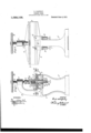
Figure 1 of the accompanying drawings is a partially sectional elevation of a forming press constructed in accordance with my invention, and Fig. 2 is an elevation at right angles to that of Fig. 1.
Referring to the drawings, the strtlipture here shown comprises a body men'rr 1 which maj be supported from any sfiitable base 1 a bed plate 2 secured to the body member, and a bracket arm 3 which is intogral therewith from.
A pair of angle plates 4 and 5 are disposed on the bed plate 2 in substantially parallel planes and a pressure member 6 having a plane bottom surface 7 is suspended from a feed screw 8 which is substantially vertical and is threaded through a hub 9 upon the end of the bracket 3. A hand wheel 10 is secured to the upper end of the feed screw 8, and a rotatable connection is established between the lower end of the feed screw and the pressure member so that the latter may be raised and lowered without being turned on its axis as the hand wheel is rotated. The angle plates 1 and 5 and pressure members 6 are equal in length and their actual length will be determined by the nature of the work for which the press is intended.
The angle plates are similar to each other and extends upwardly'thereis transmitted to the. bar
and each is provided witha lateral projcctlon 11 which extends throughout its whole length and produces a shoulder on its vertical pressure surface. A bar 12, which is slightly less in width than the thickness of the article to be formed, rests on the shoulders provided by the projections 11 and is adapted to have the worlc laid upon it be fore the pressure is applied. The angle plates 1 and 5 may be adjusted laterally, by means offscrews 13, which are threaded through projections Lt on the bed plate 2, and engage cup-shapedrecesses 15 in th'e' outer edges ot thc said angle plates. I
The adjacent edges of the angle plates are raised slightly from the bed plate 2, by means of spring-supported rods 113, except when the pressure member ,(5 is forced into engagement with the upper surface of a tube 17, which is intended to be illustrative of any suitable object. in process of formation on the press. Each of the rods 16/ is provided with a head or engagement 1b? which is adapted to lie in a recess 2 in the bed plate 2, through which the rod 16 projects except when the downward pressure of the member 6 is withdrawn. A spring 19, which is coiled aboutthe shank 18 of the rod 16 to force the rod upwardly and a nut 20 is provided for adjusting said spring. Tubes or guides 21 are secured to the base 1 to provide continuations of the holes in the bed plate through which the rods 16 project. The lower end of each of the tubes 21 is internally screwdln'eaded .to receive the nut 20.
The operation of the press is as follows: Assuming that an insulating tube has been softened and forced upon a mandrel 22 of rectangular shape in cross section, if the tube and mandrel are laid upon the bar 12 of the press, shown in Fig. 'l of the drawings, it may be permanently formed into the shape which it has assumed by rotating the hand wheel 10 to bring the pressure member 6 into engagement with the surface directly opposite the bar 12. The downward pressure upon the mandrel l2 and from thence through the prbjections 11 to the rod 16, which are consequently forced down wardly below the surface of the bed plate 2 in opposition to the springs 19. Since the adjusting screws 13 prevent the angle plates from separating at their lower edges, a
continued downward pressure on the tube or mandrel will serve to throw the upright portions of the angle plates into engagement with the sides of the tube and thereby compress the tube between their inner faces.
It is obvious that the structural details of the press may be modificd,to accommodate different kinds of work, and I desire that variations which do not depart from the spirit of my inventionshall be included within its scope.
I claim as my invention:
1. A forming press comprising vertically movable bottom and top pressure plates and laterally movable side plates that are interlocked with the bottom plate, and means for moving the top plate to engage the upper edges of the side plates and move them toward each other to compress an interposed object between them.
2. A forming press comprising a base plate, a pair of angle plates having substantially parallel 'upwardly projecting sides and lateral projections on their adjacent vertical faces, a bottom platerloca ted between the angle plates and resting on said projections, -a top plate adjustably supported above the side plates and parallel to the base plate, adjustable means for limiting the lateral displacement of the angle plates, and yielding means acting upwardly upon the lateral projections of the angle plates.
3. A forming press comprising a base plate having projecting lugs, a pair of angle plates disposed between the lugs on the base plate, adjusting screws threaded through the lugs and engaging the outer edges of the angle plates, at bottomplate disposed between the angle plates and resting on lateral projections thereof, a pressure plate adjustably supported above the angle plates and having its bottom surface paralleLto the base plate, and spring-actuated rods which project through the base plate and are adapted to lift the adjacent corners of the angle plates from the base plate when the downward pressure of the top plate removed.
EMIL HAJQFELY;
\Vitnesses: o
R. J. DEARBORN, B. B. HINEs.
In testimony whereof, I have hereunto'fi? subscribed my name this 8th day of Ji1ly,
Priority Applications (1)
| Application Number | Priority Date | Filing Date | Title |
|---|---|---|---|
| US50700109A US1028108A (en) | 1909-07-10 | 1909-07-10 | Forming-press. |
Applications Claiming Priority (1)
| Application Number | Priority Date | Filing Date | Title |
|---|---|---|---|
| US50700109A US1028108A (en) | 1909-07-10 | 1909-07-10 | Forming-press. |
Publications (1)
| Publication Number | Publication Date |
|---|---|
| US1028108A true US1028108A (en) | 1912-06-04 |
Family
ID=3096401
Family Applications (1)
| Application Number | Title | Priority Date | Filing Date |
|---|---|---|---|
| US50700109A Expired - Lifetime US1028108A (en) | 1909-07-10 | 1909-07-10 | Forming-press. |
Country Status (1)
| Country | Link |
|---|---|
| US (1) | US1028108A (en) |
Cited By (1)
| Publication number | Priority date | Publication date | Assignee | Title |
|---|---|---|---|---|
| US3790330A (en) * | 1972-05-04 | 1974-02-05 | Phillips Petroleum Co | Compact press and pellet plunger |
-
1909
- 1909-07-10 US US50700109A patent/US1028108A/en not_active Expired - Lifetime
Cited By (1)
| Publication number | Priority date | Publication date | Assignee | Title |
|---|---|---|---|---|
| US3790330A (en) * | 1972-05-04 | 1974-02-05 | Phillips Petroleum Co | Compact press and pellet plunger |
Similar Documents
| Publication | Publication Date | Title |
|---|---|---|
| CN107511684A (en) | A pipe bending machine with cutting function | |
| CN213198926U (en) | Tablet press for pharmacy that depth of charge can be finely tuned | |
| CN112320566B (en) | Hanging clamp | |
| CN115673120A (en) | Tertiary forming die of omega type bullet strip suitable for 35t heavy load railway | |
| CN108323018A (en) | A kind of circuit board processing clamping device | |
| CN104669624A (en) | Delta 3D (three-dimensional) printer | |
| CN204052505U (en) | A kind of copper coin book joint setting machine | |
| CN202205597U (en) | Aluminum shell fixing device | |
| CN112489903A (en) | Automatic processing equipment for insulating element for electrical equipment | |
| US1778339A (en) | Die holder | |
| CN209257747U (en) | A kind of engraving machine with plate fixing device | |
| CN209440028U (en) | A kind of precise positioning fixture suitable for producing ultraprecise feeler gauge cubing | |
| CN102327999B (en) | Mechanical clamping device for numerical control dividing, notching and winding machine | |
| US931760A (en) | Device for forming molds to produce screw-threaded castings. | |
| CN212371708U (en) | Stepped shaft drilling clamp | |
| CN212536499U (en) | A mutation disc spring | |
| US916215A (en) | Former for screw-driver blades. | |
| CN205914574U (en) | A suppression device for right angle type of bending parts machining | |
| US1877251A (en) | Tapping machine | |
| CN217990788U (en) | External wire pressing device for wire cutting machine | |
| CN206507299U (en) | Cavity mandrel positioning device | |
| CN106736737B (en) | A kind of rod and tube kind material processing support device | |
| CN219425564U (en) | Valve electric upsetting forming device | |
| US275298A (en) | Manufacture of glassware | |
| CN220349041U (en) | A clamping tool for automotive plastic products |