US10279155B1 - Methods and systems for bathing nose and sinus passages - Google Patents
Methods and systems for bathing nose and sinus passages Download PDFInfo
- Publication number
- US10279155B1 US10279155B1 US14/070,815 US201314070815A US10279155B1 US 10279155 B1 US10279155 B1 US 10279155B1 US 201314070815 A US201314070815 A US 201314070815A US 10279155 B1 US10279155 B1 US 10279155B1
- Authority
- US
- United States
- Prior art keywords
- head
- user
- liquid
- fluid
- tube
- Prior art date
- Legal status (The legal status is an assumption and is not a legal conclusion. Google has not performed a legal analysis and makes no representation as to the accuracy of the status listed.)
- Active, expires
Links
Images


Classifications
-
- A—HUMAN NECESSITIES
- A61—MEDICAL OR VETERINARY SCIENCE; HYGIENE
- A61M—DEVICES FOR INTRODUCING MEDIA INTO, OR ONTO, THE BODY; DEVICES FOR TRANSDUCING BODY MEDIA OR FOR TAKING MEDIA FROM THE BODY; DEVICES FOR PRODUCING OR ENDING SLEEP OR STUPOR
- A61M31/00—Devices for introducing or retaining media, e.g. remedies, in cavities of the body
-
- A—HUMAN NECESSITIES
- A61—MEDICAL OR VETERINARY SCIENCE; HYGIENE
- A61H—PHYSICAL THERAPY APPARATUS, e.g. DEVICES FOR LOCATING OR STIMULATING REFLEX POINTS IN THE BODY; ARTIFICIAL RESPIRATION; MASSAGE; BATHING DEVICES FOR SPECIAL THERAPEUTIC OR HYGIENIC PURPOSES OR SPECIFIC PARTS OF THE BODY
- A61H35/00—Baths for specific parts of the body
- A61H35/04—Baths for specific parts of the body for the nose
-
- G—PHYSICS
- G01—MEASURING; TESTING
- G01C—MEASURING DISTANCES, LEVELS OR BEARINGS; SURVEYING; NAVIGATION; GYROSCOPIC INSTRUMENTS; PHOTOGRAMMETRY OR VIDEOGRAMMETRY
- G01C9/00—Measuring inclination, e.g. by clinometers, by levels
- G01C9/02—Details
- G01C9/06—Electric or photoelectric indication or reading means
-
- A—HUMAN NECESSITIES
- A61—MEDICAL OR VETERINARY SCIENCE; HYGIENE
- A61H—PHYSICAL THERAPY APPARATUS, e.g. DEVICES FOR LOCATING OR STIMULATING REFLEX POINTS IN THE BODY; ARTIFICIAL RESPIRATION; MASSAGE; BATHING DEVICES FOR SPECIAL THERAPEUTIC OR HYGIENIC PURPOSES OR SPECIFIC PARTS OF THE BODY
- A61H2201/00—Characteristics of apparatus not provided for in the preceding codes
- A61H2201/16—Physical interface with patient
- A61H2201/1602—Physical interface with patient kind of interface, e.g. head rest, knee support or lumbar support
- A61H2201/1604—Head
-
- A—HUMAN NECESSITIES
- A61—MEDICAL OR VETERINARY SCIENCE; HYGIENE
- A61H—PHYSICAL THERAPY APPARATUS, e.g. DEVICES FOR LOCATING OR STIMULATING REFLEX POINTS IN THE BODY; ARTIFICIAL RESPIRATION; MASSAGE; BATHING DEVICES FOR SPECIAL THERAPEUTIC OR HYGIENIC PURPOSES OR SPECIFIC PARTS OF THE BODY
- A61H2201/00—Characteristics of apparatus not provided for in the preceding codes
- A61H2201/50—Control means thereof
- A61H2201/5023—Interfaces to the user
- A61H2201/5043—Displays
-
- A—HUMAN NECESSITIES
- A61—MEDICAL OR VETERINARY SCIENCE; HYGIENE
- A61H—PHYSICAL THERAPY APPARATUS, e.g. DEVICES FOR LOCATING OR STIMULATING REFLEX POINTS IN THE BODY; ARTIFICIAL RESPIRATION; MASSAGE; BATHING DEVICES FOR SPECIAL THERAPEUTIC OR HYGIENIC PURPOSES OR SPECIFIC PARTS OF THE BODY
- A61H2205/00—Devices for specific parts of the body
- A61H2205/02—Head
- A61H2205/022—Face
- A61H2205/023—Nose
-
- A—HUMAN NECESSITIES
- A61—MEDICAL OR VETERINARY SCIENCE; HYGIENE
- A61M—DEVICES FOR INTRODUCING MEDIA INTO, OR ONTO, THE BODY; DEVICES FOR TRANSDUCING BODY MEDIA OR FOR TAKING MEDIA FROM THE BODY; DEVICES FOR PRODUCING OR ENDING SLEEP OR STUPOR
- A61M2210/00—Anatomical parts of the body
- A61M2210/06—Head
- A61M2210/0618—Nose
-
- A—HUMAN NECESSITIES
- A61—MEDICAL OR VETERINARY SCIENCE; HYGIENE
- A61M—DEVICES FOR INTRODUCING MEDIA INTO, OR ONTO, THE BODY; DEVICES FOR TRANSDUCING BODY MEDIA OR FOR TAKING MEDIA FROM THE BODY; DEVICES FOR PRODUCING OR ENDING SLEEP OR STUPOR
- A61M2210/00—Anatomical parts of the body
- A61M2210/06—Head
- A61M2210/0681—Sinus (maxillaris)
Definitions
- the human nasal cavity extends from the nares to the choana. Extending from this space, which is roughly rectangular, are four sets of sinuses which are hollow spaces in the bone of the head. The sinuses extend above, below, medial to and posterior to the boney orbit.
- the nasal and sinus cavities are normally able to clear mucous produced in their linings through a transport system called the mucociliary blanket, a self-cleaning lining of the nose and sinuses.
- the mucous is transported out of the sinus openings which vary from 1 mm in diameter to 2 cm in diameter and, in some cases, can be even larger.
- FIG. 5C is a top view in section of a portion of the display of FIG. 5B .
- FIG. 6B is a partially diagrammatic view in elevation a head position display portion of the Head Orientation Unit of FIG. 6A .
- FIG. 6D is a top view in plan of the portion of the display of FIG. 6C but showing a predetermined path of head movement for the user during use of the system of the invention.
- FIGS. 6E and 6F illustrate partial arrays of bubble levels.
- FIG. 9 is a partially diagrammatic view in elevation of a Head Orientation Unit according to yet another embodiment of the present invention.
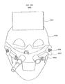
- FIGS. 4A through 4D illustrate Head Orientation Unit 1400 comprising an attachment member or head interface member 1410 shown secured to a user's head ( FIG. 4D ), a spacer arm 1420 , display support arm 1430 , and bubble level device 1440 .
- Head interface member 1410 functioning as an attachment member to the user, can be a set of goggles held in place on the patient's/user's head by an elastomeric strap, a head band, a visor, or any other device that can be temporarily secured to and move with the patient's head.
- the display can be all or a part of a toroidal shell.
- the radius of curvature in one-dimension is much less than the radius of curvature in the perpendicular direction.
- FIGS. 5A through 5D, 6A through 6F, 7A and 7B, 8A through 8C, 9, and 10A and 10B pertain to the details of alternative Head Orientation Units.
- the app then communicates to the user visually via the mobile device display and/or aurally via the mobile device speaker as regarding which way the user should moves his head or to provide other directions for the use of the system. Because the mobile device 2030 is able to detect changes in its orientation with respect to the vertical while also detecting the orientation of the user's head with respect to the mobile device 2030 , the mobile device can be held in the user's hand and still provide precise feedback to the user regarding the orientation of his head with respect to the prescribed orientation for the specific time for the specific preselected mode.
- the illustrated LOID can be used for the app to report in real time to the physician the identity of the user, and can also provide information as to which modes are used at what times. This permits the physician to monitor the proper use of the device and the app and/or the physician to correlate specific treatments to the results of the treatment.
- the water flow forces the air in pressure container 3050 through outlet tubing 3080 extending through pressure-tight plug 3030 .
- Male Luer lock 3075 at the end of tubing 3080 forms a fluid-tight seal with female Luer lock connector 350 on removable tip member 310 .
- the turbine is coaxial with, and thus drives, an air pump that pumps air through outlet tubing 3280 .
- Male Luer lock 3275 at the end of tubing 3280 forms a fluid-tight seal with female Luer lock connector 350 on removable head unit 310 .
- Fresh air enters the pump via air inlet 3285 .
- a fifth source of pressurized gas can be a gas generated from a chemical reaction, such as CO 2 generated from the reaction of sodium bicarbonate and an acid, such as citric and/or acetic acid in a pressure-tight container with a tube that connects to removable tip member 310 .
- a chemical reaction such as CO 2 generated from the reaction of sodium bicarbonate and an acid, such as citric and/or acetic acid in a pressure-tight container with a tube that connects to removable tip member 310 .
- an effervescent tablet, granules and/or powder can be added to the bathing fluid in syringe 260 before the fluid is introduced into the nasal cavity and/or sinuses.
- the solids can be preinstalled in syringe 260 and the fluid added just before use.
- the solids can be a mixture of solid sodium bicarbonate and citric acid and the fluid can be water.
- the fluid can be an acidic solution of, for example, citric and/or acetic acid and the solid can be sodium bicarbonate.
- the fluid can be a solution of sodium bicarbonate and the solid can be citric acid.
- FIGS. 14A through 14F , FIGS. 15A and 15B , and FIGS. 16A and 16B relate to alternative nozzles for Fluid Introduction and Retention Units.
- FIGS. 14A through 14F relate to alternative nozzles for Fluid Introduction and Retention Units.
- FIG. 14A illustrates alternative nozzle 4400 used with Fluid Introduction and Retention Unit 5000 A, a variant of Fluid Introduction and Retention Unit 5000 described in greater detail in relation to FIG. 18 below.
- outlet arms 5020 both connect directly to the single nozzle 4400
- each of the two outlet arms 5020 is connected directly to a separate nozzle.
- the direct connection of both outlet arms 5020 to the single nozzle 4400 is assisted by an optional narrow extension 5035 .
- FIG. 16A illustrates in detail a cross-section of mechanically induced turbulence nozzle 4600 .
- Female Luer connector 4654 on the lower end of nozzle input tube 4652 screws into male Luer lock 365 on syringe 360 , attaching mechanically induced turbulence nozzle 4600 to syringe 360 .
- the upper end of nozzle input tube 4652 directs the flow of fluids into the turbulence chamber 4628 .
- Inner shell 4620 defines most of the turbulence chamber 4628 .
- Driver drive wheel 4773 drives nozzle drive wheel 4626 at the lower end of shaft 4624 .
- Shaft 4626 has turbulence propeller 4622 affixed to its upper end.
- FIG. 16B illustrates in detail a cross-sectional view of mechanically induced turbulence nozzle 4700 .
- Female Luer connector 4754 on the lower end of nozzle input tube 4752 screws into male Luer lock 365 on syringe 360 , attaching mechanically induced turbulence nozzle 4700 to syringe 360 .
- the upper end of nozzle input tube 4752 directs the flow of fluids into the turbulence chamber 4728 .
- Inner shell 4720 defines most of the turbulence chamber 4728 .
- Driver drive wheel 4773 drives nozzle drive wheel 4726 at the lower end of flexible shaft 4725 to shaft 4724 .
- Arm 4730 supports the lower portion of shaft 4725 .
- Arms 4744 support the 4724 .
- FIGS. 17A through 17C relate in detail to an alternative Fluid Introduction and Retention Unit 4800 . It is important to visualize the results of sinus surgery. This can be done using a Fluid Introduction and Retention Unit to introduce fluids into the sinuses while the patient is in an MRI unit. The MRI shows fluids in the sinuses when present. In an MRI unit, the patient must lay with his arms at his side. However, this prevents the patient from holding other Fluid Introduction and Retention Units in contact with the entrance of the nasal cavity. To resolve this problem, a hands-free Fluid Introduction and Retention Unit is provided in accordance with another aspect of the invention. FIG.
- FIGS. 19C through 19O illustrate the fluid circuit structures inside of Fluid Introduction and Retention Unit 5200 .
- FIG. 19N is a view of the fluid circuit illustrated in FIG. 19C rotated 90° clockwise.
- FIG. 19O is a view of the fluid circuit illustrated in FIG. 19D rotated 90° clockwise.
- the fluid flows into Fluid Introduction and Retention Unit 5200 via tube 5262 , then through tube 5263 , then through tube 5254 .
- FIGS. 19D through 19M and 19O illustrate the fluid circuit structures and the flow of fluids inside of Fluid Introduction and Retention Unit 5200 when button 5242 is pressed.
- FIG. 19O is a view of the fluid circuit illustrated in FIG. 19D rotated 90° clockwise.
- fluid flows into Fluid Introduction and Retention Unit 5200 via tube 5262 .
- button 5242 is not pressed the fluid flows from tube 5254 through tube 5274 , then through elastic tube 5276 , then tube 5278 , then into tube 5267 , through tube 5268 , through tube 5269 to tube 5226 through nozzle 5228 and into nozzle 5214 .
- FIGS. 20A and 20B illustrate a double-nozzle Fluid Introduction and Retention Unit 5300 , which is a version of Fluid Introduction and Retention Unit 5200 with a built-in peristaltic pump. Pressing on spring-biased peristaltic motor switch 5390 turns on peristaltic pump motor 5394 . Its spring (not illustrated) is much weaker than spring 5348 and thus the peristaltic pump motor is turned on without depressing button 5344 . Fluid flows into main body 5330 through tube 5362 into the elastic peristaltic pump input path tube 5395 . The fluid flows out of peristaltic pump input path 5395 to tube 5391 . Fluid flows into peristaltic elastic pump output path tube 5396 from tube 5398 .
- Peristaltic arm assembly is comprised of arms 5450 , a mounting plate 5413 affixed at end of each arm 5450 . Affixed to each plate 5413 is a pair of end plates 5412 's that support respective axles 5411 .
- One axle 5411 supports and allows pump wheel 5292 to turn freely, the other axle 5411 supports and allows pump wheel 5497 to turn freely.
- Peristaltic pump input path tubes 5495 and 5496 are not coplanar. Thus, when a rocker 5426 is in the orientation illustrated in FIG. 21A , peristaltic pump wheels 5492 and 5497 mounted on the ends of peristaltic driving pump arms 5494 engage only pump input path tube 5495 when the unit is in the mode illustrated in FIG. 21C .
Abstract
A system and method for delivering a bathing liquid via a nostril of a face-down user maintains the liquid in prolonged and predictable contact with the nasal and sinus mucosa. A head orientation unit attaches to the head and includes an angle monitoring unit to provide an indication of the angular orientation of the head as it turns to optimize delivery of the liquid to target head structures. A liquid supply delivers the liquid through the user's nostrils to the selected head structures as a function of the angular orientation indication and at a pressure and flow rate that maintains a constant volume of liquid in the nasal and sinus cavities. Indicia on the angle monitoring unit permit the user to orient his/her head to predetermined angular positions.
Description
This application claims priority to U.S. Provisional Application No. 61/796,105, filed Nov. 2, 2012, by Michael Bart Siegel et al and entitled “Method And Apparatus For Bathing Nose And Sinuses”, and to U.S. Provisional Application No. 61/852,192, filed Mar. 16, 2013, by Michael Bart Siegel et al and entitled “Method And Apparatus For Bathing Nose And Sinuses”, the disclosures in which are incorporated herein in their entireties by this reference.
The present invention pertains to methods and systems for providing the nose, sinuses and other cavity and passage structures with prolonged exposure to a bathing fluid to clean and/or medicate those structures and/or to deliver drugs directly into the bloodstream and/or through the olfactory bulb/cleft to bypass the blood/brain barrier and first pass effect in the liver.
In addition, the invention pertains to angular displacement monitoring devices and methods for monitoring two dimensions of angular displacement from a vertical axis.
The human nasal cavity extends from the nares to the choana. Extending from this space, which is roughly rectangular, are four sets of sinuses which are hollow spaces in the bone of the head. The sinuses extend above, below, medial to and posterior to the boney orbit. The nasal and sinus cavities are normally able to clear mucous produced in their linings through a transport system called the mucociliary blanket, a self-cleaning lining of the nose and sinuses. The mucous is transported out of the sinus openings which vary from 1 mm in diameter to 2 cm in diameter and, in some cases, can be even larger. Normally, the mucous is then cleared out of the nasal cavity into the nasopharynx and down into the pharynx where it is swallowed. The mucocilliary blanket clears out viruses, bacteria, fungi and other debris from the nose and sinuses so that they do not have the ability to cause infection, both locally and systemically.
Sinusitis is caused by obstruction to the sinus ostia, or a breakdown of the mucocilliary clearance. The obstruction is caused by mucosal edema from viruses, allergies or any other irritants in inspired air. With the sinus ostia obstructed, mucous produced in the sinus accumulates and provides a perfect medium in which bacteria can grow. If an infection occurs, this leads to pressure in the sinus with facial pressure/pain, nasal obstruction, thick purulent nasal and post-nasal discharge and generalized fatigue.
Conventionally, patients are treated for sinusitis with oral antibiotics, steroid nasal sprays, decongestants and, occasionally, oral steroids. Nasal irrigations are used as well and are effective in clearing debris from the nasal cavity but are very irritating to the Eustachian tubes and pharynx. If the sinusitis does not clear after maximal medical therapy, or if the infections recur frequently, then surgery must be considered to enlarge the openings to the sinuses. Once the sinus openings have been enlarged, the sinuses are more accessible but are still poorly accessible with currently available nasal/sinus irrigation units. Sometimes the surgery is performed only with the idea that it will render sinus irrigations more effective. Even after such surgery, and despite the availability of many different devices, accessing the sinuses with saline or medicated liquid to clear the infection is still very ineffective.
In an article by Peter Wormald et al entitled “A Comparative Study of Three Methods of Nasal Irrigation” (Laryngoscope. 2004 December; 114(12):2224-7), the available methods of nasal and sinus irrigation are detailed and compared. The three techniques described are: nebulization (rhinoflow); nasal irrigation (metered nasal spray); and nasal irrigation in the Moffit's position (nasal douching with the top of the head positioned on the floor).
Nebulized medications are ineffective in entering the sinuses in any reliable fashion. Nasal rinse bottles are often effective in clearing the nose, but the irrigant rarely enters the sinus in any significant way. Even if the irrigant or nebulized saline enters the sinus, the contact time is very transient and unpredictable, thereby significantly minimizing its effectiveness. One reason for this is that the orientation of the user's head during fluid application is preferably face-down to permit the liquid to have access to all of the intended cavities. However, when the face down position is assumed in these prior techniques, the liquid tends to quickly flow out of the nasal passages without sufficient residence time to be effective and without contacting the target areas. To compensate for this some prior techniques for irrigation of the nose and sinuses introduce excess liquid into the nasal passage, often causing users to experience Eustachian tube irritation with subsequent ear pain and the discomfort of fluid draining into their throats, making them cough and choke.
Most conventionally used methods of delivering medication systemically through the nasal cavity are inaccurate and ineffective because of the transient and unpredictable contact time between the medication and the target membrane.
In one aspect, the present invention pertains to improving the effectiveness of bathing/irrigating and medicating nasal passages and sinus cavities by permitting selective increase in the residence time of the applied fluid in those head structures. Specifically, a primary use of the apparatus of the present invention is to provide prolonged and predictable contact with the nasal and sinus mucosa by a bathing fluid, and to deliver a saline bath or medication locally to the nose and sinuses to treat nasal/sinus conditions. The bathing fluid can be any fluid, preferably a liquid, that benefits the patient/user. This can include hypotonic, isotonic, and/or hypertonic saline and/or medications. The bathing fluid can be used to treat various nasal and sinus conditions including nasal/sinus infections and epistaxis.
The invention is also intended to provide prolonged and predictable contact to the nasal/sinus membranes, olfactory bulb and cleft by a bathing fluid to deliver medications systemically. The bathing fluid may include medications absorbed through the olfactory bulb, olfactory cleft or nasal and sinus mucosa. When medications are absorbed by the olfactory bulb, they bypass the liver, thereby protecting the medications from being altered by the liver. For this reason, and because medications absorbed through the olfactory bulb also bypass the blood/brain barrier, this invention provides an important medication delivery system.
To achieve the above and other results, the system of the present invention includes three primary components, namely, a Head Orientation Unit, a Fluid Introduction and Retention Unit and, optionally and preferably, a Fluid Agitation Unit, all of which individually and in concert comprise inventions disclosed herein.
The present invention allows the bathing liquid/fluid to bathe the nasal/sinus mucosa, olfactory cleft/bulb, by filling the nasal cavity and sinuses for various predefined periods of time.
In use, the Head Orientation Unit is first removably secured on the head of the patient/user, the unit being such that the unit orientation changes as the orientation of the head changes. The Head Orientation Unit may include any attachment member or device that can be temporarily affixed to the user's head, such as goggles with a strap or elastic band, a visor or cap, a helmet, etc. With the Head Orientation Unit in place and the user facing downward to look substantially at the floor, a head position indicator is suspended by a spacer bar from the attachment member below the user's face. The user then orients his/her head more precisely by tilting his/her head such that the head position indicator (e.g., a leveling bubble in one preferred embodiment) on a display unit is aligned with a mark or indicium that specifies the proper head orientation to bathe a particular target sinus or nasal structure. Different variations of this orientation of the head provide the optimal exposure to different sinuses or nasal structures, and each is associated with a respective indicium or mark. The Head Orientation Unit can also be used to define specific changes in the head orientation as may be useful, such as the Head Orientation Unit's ability to define a series or path of head orientations to cause the bathing fluid to enter certain specific areas of the nose and sinuses.
The Fluid Introduction and Retention Unit permits the user to “fill” the nasal cavity from the bottom, one or both sides at a time; in other words, the Fluid Introduction and Retention Unit establishes and supports a column of the bathing liquid in the nasal cavity to provide prolonged exposure to the liquid of structures in the cavity. Thus, the sinus cavities extending from the nasal cavity are reliably filled with bathing fluid, typically a saline or medicament liquid. In addition, filling one side of the nose until the smallest drop of bathing fluid is noted coming out of the opposite nares ensures no irritation to the user's Eustachian tube and that there is no discomfort of fluid draining into the throat. Keeping the head in this position allows the bathing fluid to remain in the sinuses indefinitely until the user releases the Fluid Introduction and Retention Unit from contact with the nostril, allowing the fluid to readily drain from the nose. Importantly, with this arrangement the liquid column in the nasal cavity is supported against gravity by the Fluid Introduction and Retention Unit in spite of the user facing directly downward.
The capacity of the syringe can vary depending upon how it is used; a 30 mL syringe is sufficient for many applications. The syringe is provided with gradation indicia to permit simple measurement of the amount of bathing fluid to be inserted. It is a simple matter to fill the Fluid Introduction and Retention Unit syringe by drawing the bathing fluid up through the syringe from its distal end.
The Fluid Agitation Unit can be used to introduce an agitation fluid, such as air, into the bathing liquid filling the nasal and sinus cavities. The agitation fluid creates turbulence in the liquid which assists in “scrubbing” the walls of the cavity structures to remove the thick sticky mucous and debris associated with inflammation and infection. Such aeration of the bathing liquid also assists in allowing the bathing fluid to fill the sinuses completely even in non-operated sinuses. It also creates a gentle massaging of the inside of the nose that soothes the tissue and simulates flushing the nose and sinuses without the discomfort of having saline flush into the Eustachian tubes and throat and mouth. Although aeration is one preferred form of creating the desired turbulence in the bathing liquid, other turbulence inducing means can be used as described hereinbelow.
In another aspect of the invention the bathing liquid is supplied in cartridges that can be pressurized (e.g., at the Fluid Introduction and Retention Unit) to deliver prescribed fluid volumes of bathing liquid. The complete or partial pre-filling of cartridges provides important benefits, such as convenience to the user as it eliminates the need to for the user to sterilize the bathing liquid. Another benefit of the cartridges is that the amount of fluid to be delivered is precisely controlled.
Another aspect of the present invention, independent of the sinus bathing application, is the provision of a novel general-purpose high-precision analog device for measuring angular deflection from vertical in two dimensions.
The above and still further features and advantages of the present invention will become apparent upon consideration of the following definitions, descriptions and figures of specific embodiments thereof wherein like reference numerals in the various drawing FIGS. are utilized to designate like components. While these descriptions go into specific details of the invention, it should be understood that variations may and do exist and would be apparent to those skilled in the art based on the descriptions herein.
As illustrated in FIGS. 4B, 4C and 4D , bubble level device 1440 has a gas bubble 1450 in a liquid 1443 confined to a portion of a spherical shell. The shell is defined by a truncated spherical outer shell wall 1442 and a concentric truncated spherical inner shell wall 1444. This configuration maximizes the display area while minimizing the volume and weight of liquid 1443 in the bubble level device. Concentric spherical shell walls 1442 and 1444 can be vacuum formed from thin sheets of EVA, ethyl vinyl acetate, 0.020″ in thickness. In one preferred embodiment the outer shell wall 1442 is thermoformed to an outer radius of curvature of 1.16″, the spherical portion 2″ in outer diameter; the inner shell wall 1444 is thermoformed to be parallel to and with a 0.1″ distance between it and the outer shell wall 1442. The reveal 1446 of the outer shell wall 1442 is fused to a reveal 1449 of the inner shell wall 1444, for example, by ultrasonic welding. The reveal 1449 of the inner shell wall 1444 is fused to the acrylic display support arm 1430.
In fabricating the level device, a tapered hollow needle can pierce the reveal 1449 of the inner shell wall 1442. The needle can then be withdrawn slightly, the tip still inside the shell. The result is a hole or aperture 1448 extending through inner shell wall 1442. The slight withdrawal of the needle leaves an air gap between outside of the needle and aperture 1448. The gap permits air to escape the shell while it is being filled with liquid 1443. The liquid 1443 is injected through the hollow needle into the shell. Enough liquid 1443 is introduced into aperture 1448 to fill the shell, except for the small amount that will produce bubble 1450. After the shell is sufficiently filled, the hollow needle is withdrawn and aperture 1448 can be sealed by adhesive tape, or the like. The shell is protected from damage caused by potential freezing of the liquid 1443 by using, for example, a concentrated saline solution as the liquid 1443. The liquid 1443 can be colored by the addition of a colorant such as hydrophilic ultramarine pigment.
Numerals “1” through “6” provided in respective indicia 1447 illustrate how a path of successive head orientations can be defined on the display for a particular irrigation or other treatment. For example, the user first adjusts his/her head to the orientation marked “1”, then to the orientation marked “2”, and so on, in sequence.
The display is shown as having a circular periphery; however, this shape can be different depending upon the optimal variations in useful display angles for various treatment modalities.
Other shapes can be used for such large display, light-weight bubble level devices. For example, the display can be all or a part of a toroidal shell. Here the radius of curvature in one-dimension is much less than the radius of curvature in the perpendicular direction.
The radius of curvature at a particular orientation can be varied such that it is smaller where the preferred resolution is less, and larger where the preferred resolution is greater. For example, a shell bounded, at least in part, by parallel ellipsoids of revolution will have a greater resolution the closer the major axes of the ellipsoids are to horizontal. The curvature of the shell walls can be any of many curves, such as the sums of trigonometric, polynomial and/or other functions and/or combinations thereof. To minimize the weight and volume of the fluid while optimizing the display area, the shell at a particular orientation of the level should have a thickness slightly greater than the depth of the bubble for each useful orientation of the level device.
In addition to its use in the present invention to display head orientation, the thin shell bubble head orientation unit is a novel general-purpose high-precision analog device for measuring angular deflection from vertical in two dimensions. As used in the head orientation display described herein, the two dimensions are roll (rotation about the axis extending longitudinally through the spine) and yaw (rotation perpendicular to that axis).
The descriptions immediately below and FIGS. 5A through 5D, 6A through 6F, 7A and 7B, 8A through 8C, 9, and 10A and 10B pertain to the details of alternative Head Orientation Units.
Another variant of the embodiment illustrated in FIG. 8C uses the display of a mobile device on a platform to replace display 1840. An app running on the mobile device can display one or a series of spots to direct the user to orient his head such that the display plumb pointer 1850 is aligned to the appropriate spot on the mobile device display at the proper time and for a pre-defined duration.
Water flows from the faucet through inlet tube 3060 extending through pressure-tight plug 3030 into pressure container 3050. The water flow forces the air in pressure container 3050 through outlet tubing 3080 extending through pressure-tight plug 3030. Male Luer lock 3075 at the end of tubing 3080 forms a fluid-tight seal with female Luer lock connector 350 on removable tip member 310.
A fourth alternative source of gas under pressure for the Fluid Agitation Unit 370 can come from devices for dispensing CO2 from CO2 cartridges such as commercially available beer dispensers.
A fifth source of pressurized gas can be a gas generated from a chemical reaction, such as CO2 generated from the reaction of sodium bicarbonate and an acid, such as citric and/or acetic acid in a pressure-tight container with a tube that connects to removable tip member 310.
Another alternative is for the gas-generating chemical reaction to occur in the fluid column supported by the Fluid Introduction and Retention Unit. In one embodiment an effervescent tablet, granules and/or powder can be added to the bathing fluid in syringe 260 before the fluid is introduced into the nasal cavity and/or sinuses. The solids can be preinstalled in syringe 260 and the fluid added just before use. The solids can be a mixture of solid sodium bicarbonate and citric acid and the fluid can be water. Alternatively, the fluid can be an acidic solution of, for example, citric and/or acetic acid and the solid can be sodium bicarbonate. Alternatively, the fluid can be a solution of sodium bicarbonate and the solid can be citric acid.
The nozzle assembly support structure main body 4849 is flexible, increasing the ability to adjust the nozzle assembly support structure to each specific user. Rigid plastic support tube 4842 is affixed to the nozzle assembly support structure main body 4849 and aligns and supports rigid nozzle extension tube 4845 with respect to main body 4849. Nylon screw 4844 is used to adjust the extension of the nozzle 4847 with respect to main body 4849. Nylon screw 4844 screws into 4843, a rigid threaded part of plastic support tube 4842. Nylon screw 4844 extends through threaded piece 4843 to contact nozzle extension tube 4845. Loosening nylon screw 4844 a little allows nozzle extension tube 4845 to slide freely (though snugly) in plastic support tube 4842. Tightening nylon screw 4844 prevents nozzle extension tube 4845 from sliding in plastic support tube 4842, thereby locking its location and orientation.
More specifically, a spring-biased actuator button 5244 is at the distal or external end of a rod 5242. Rod 5242 passes through and is rigidly affixed to tube block 5284. A spring block 5248 is rigidly affixed to and proximate the internal end of rod 5242. A spring 5247 is contained at one end by the inner wall of a main body 5230 and at the opposite end by spring block 5248. The internal end of rod 5242 also helps to keep spring 5247 in place. Rod 5242 is constrained to linear motion by passing through an aperture in each rod support 5232 and 5234. Rod supports 5232 and 5234 are affixed at both ends to the inner wall of main body 5230.
When button 5244 is not pressed, spring 5247 applies force to spring block 5248 and thus to rod 5242 and tube block 5246. This force is applied to tube block 5246 and is sufficient to pinch elastic tubes 5276 and 5286 against rod support 5232 sufficiently to prevent the flow of fluids through the tubes. Elastic tubes 5256 and 5266 are not pinched by tube block 5246 and, therefore, fluids are free to flow through them.
When button 5244 is pressed, overcoming the bias force applied by spring 5247, tube block 5284 pinches elastic tubes 5256 and 5266 against rod support 5234, preventing flow of fluids through them. Likewise, elastic tubes 5276 and 5286 are not pinched by tube block 5246, and fluids are free to flow through them.
A cartridge nozzle 6010 is secured atop a cartridge neck 6070. A cartridge half-ring 6060, a cartridge tab 6020, and a cartridge Luer housing 6080 are affixed to the side of cartridge neck 6070. Within Luer housing 6080 is a female Luer connector 6040. Further inside Luer housing 6080 is a one-way valve 6030 employed to prevent the inadvertent outward flow of the fluid. Nozzle 6010, neck 6070, half-ring 6060, tab 6020, and Luer housing 6080 are typically rigid or semi-rigid. A cartridge bag 6050 contains at least the bulk of the fluid and is typically made from a very pliable material such as medical grade polyethylene film.
A cartridge nozzle cap 6090 can be a shrink wrapped covering over cartridge nozzle 6010. Nozzle cap 6090 keeps nozzle 6010 sterile and holds a cartridge nozzle plug 6100 tightly in cartridge nozzle opening 6110 to prevent leakage therefrom. Nozzle plug 6100 can be an elastomeric material.
Once cartridge 6000 is installed in Unit body 7100, Unit plunger 7200 is slid over Unit body chamber 7150. Pressing upward on plunger 7200 causes plunger tabs 7271 and 7272 to slide in vertical grooves 7170 until plunger tabs 7271 can enter body grooves 7171, and plunger tabs 7272 can enter horizontal body grooves 7172 as illustrated in FIGS. 22D, 22E, 22I, and 22M . Unit 7000, including cartridge 6000, is ready for use once cartridge nozzle cap 6090 is removed (which pulls out the affixed cartridge nozzle plug 6100 from cartridge nozzle opening 6110).
As illustrated in FIGS. 22J, 22K and 22M through 22O , squeezing the plunger 7200 into body 7100 causes cartridge bag 6050 to be squeezed and the fluid to be discharged through nozzle opening 6110 and into the user's nose. When ready, the user can press air pump switch 7195 to turn on the air pump.
Just as cartridge tab 6020 is used to install cartridge 6000 into Unit body 7100, cartridge tab 6020 is grasped to remove cartridge 6000.
Alternatively, tip member 310 and syringe 360 combined can be disposable and pre-filled with sterilized fluids, again with a cartridge nozzle cap.
Another benefit of the use of cartridges 6000 and Fluid Introduction and Retention Unit 7000 is that the amount of fluid to be delivered is precisely controlled. The volume of that cartridge can be chosen to fill or nearly fill the sinus cavity and sinuses.
The invention as described herein includes several advantages and features, as described, and further includes, but is not limited to, the capability of:
providing prolonged exposure of one or more of nasal and/or sinus membranes, including the olfactory cleft and/or the olfactory bulb, to an irrigation or medicament liquid;
supporting a liquid column within a person's nasal cavity to thereby effect prolonged residence time of the liquid in the nasal cavity;
measuring angular displacement of a person's head to permit delivery of irrigation or medicament liquid to specified target cavities and structures in a user's head;
creating turbulence in a liquid being delivered to nasal passages and sinuses to enhance nasal bathing and irrigation; and
providing cartridges of nasal bathing and irrigation fluid for convenient and safe use with the system of the invention.
The head orientation unit embodiments described herein are merely preferred examples of units having any attachment member that is temporarily affixed to the head of a person and any two dimensional angular monitoring and display device that is secured to and moves with the attachment member and the person's head to provide a display of the angular position of the head and permit the person to orient his/her head in predetermined positions and sequentially move his/her head along paths of such positions. It is to be understood that any structures or methods providing these functions are considered to be included within the scope of the present invention. As described herein, the primary use of such head orientation units is to permit bathing and/or medication liquid to be properly administered to nasal, sinus and other structures in the person's head via the person's nostrils. However, it is to be understood that such head orientation units, to the extent that they function for other applications, are considered to be included within the scope of the present invention.
It is also to be understood that the several embodiments of Fluid Introduction and Retention Units illustrated and described herein are merely exemplary of a wide variety of liquid supply means and that any units capable of performing the functions ascribed herein to such units can be utilized in the systems and methods of the present invention. Likewise, it is to be understood that the system of the invention may employ several alternative types of Fluid Agitation Units for creating turbulence in the bath liquid whereby the turbulence is introduced by pressurized gas, mechanical agitation, or electrical discharge. Further the disposable cartridges illustrated and described herein are merely exemplary and that any cartridges capable of performing the functions ascribed herein can be utilized in the systems and methods of the present invention.
Furthermore, it should be understood that the expression “liquid supply means” as used in the claims includes, for example, any one of the following described features of the present invention: (a) syringe 260, 360 and tip member 210, 310 as described herein and illustrated in FIGS. 2A-2B and 3A ; and (b) fluid cartridge 6000 including cartridge bag 6050 and cartridge nozzle 6010 as described herein and illustrated in FIGS. 22A and 22F .
Also, it should be understood that the expression “turbulence inducing means” as used in the claims includes, for example, any one of the following described features of the present invention: (a) fluid agitation unit 370 including (i) hand pump 390 as described herein and illustrated in FIG. 3C , (ii) pump 3000 with flow limiter 3062 as described herein and illustrated in FIG. 11 , (iii) water-pressured powered, turbine air pump 3200 with flow limiter 3262 as described herein and illustrated in FIG. 12 , (iv) battery-powered air pump 3490 as described herein and illustrated in FIG. 13C , (v) pressurized CO2 cartridges as described herein, and (vi) pressurized gas generated from a chemical reaction as described herein; (b) nozzles 4400 as described herein and illustrated in FIGS. 14C-14F ; (c) mechanically induced turbulence nozzles 4600, 4700 including mechanical drive unit 4770 as described herein and illustrated in FIGS. 15A-15B , or turbulence propeller 4622, 4722 as described herein and illustrated in FIGS. 16A-16B ; and (d) actuator button 5244 and associated structure for producing repetitive fluid flow reversal into and out of the user's nostrils as described herein and illustrated in FIGS. 19C-19D .
Further, it should be understood that the expression “means for applying pressure” as used in the claims includes, for example, the following described feature of the present invention: the unit plunger 7200 as described herein and illustrated in FIGS. 22B-22E .
In addition, it should be understood that the expression “bubble level unit” as used in the claims includes, for example, the following described features of the present invention: (a) the bubble level device 1440 as described herein and illustrated in FIGS. 4A-4D ; and (b) the bubble level device 1660 as described herein and illustrated in FIGS. 6A-6F .
Having described preferred embodiments of new and improved system and method for improved irrigation and medication of the sinus, nasal and other internal structures in the head of a person, and various novel components thereof, it is believed that other modifications, variations and changes will be suggested to those skilled in the art in view of the teachings set forth herein. It is therefore to be understood that all such variations, modifications and changes are believed to fall within the scope of the present invention as defined by the appended claims. Although specific terms are employed herein, they are used in a generic and descriptive sense only and not for purposes of limitation.
Claims (15)
1. A system for delivering a liquid via a user's nostrils and maintaining prolonged exposure of the liquid to one or more head structures in a user's nasal cavity and sinuses when the user is facing downward, said system comprising:
a bubble level unit configured to move with a user's head for providing an indication of an angular orientation of the user's head;
a liquid supply means for delivering the liquid through the user's nostrils to the one or more head structures, the one or more head structures determined by the indication of said angular orientation of the user's head;
the indication of the angular orientation of the user's head provided by indicia on the bubble level unit, the indicia designating the one or more head structures for selective introduction and retention of the liquid from the liquid supply means; and
turbulence inducing means for creating turbulent flow in the liquid being delivered to the one or more structures.
2. The system of claim 1 , wherein said bubble level unit includes:
a gas bubble configured to assume a position that is a function of the angular orientation of the user's head; and
the indicia demarking predetermined angular orientations of the user's head when aligned with the gas bubble.
3. The system of claim 1 , wherein said turbulence inducing means consists of a selected one of an aeration device, a mechanical agitator, a bladed propeller, a flow rate modifier and a flow direction modifier.
4. The system of claim 3 ,
wherein the turbulence inducing means is selected to be the aeration device; and
wherein the aeration device is a fluid agitation unit consisting of one of a hand pump, a powered air pump, a pressurized CO2 cartridge, and a pressurized gas generated from a chemical reaction of effervescent tablets, granules and/or powder added to the liquid.
5. The system of claim 3 ,
wherein the turbulence inducing means is selected to be the mechanical agitator; and
wherein the mechanical agitator is a mechanical drive unit coupled to a mechanically induced turbulence nozzle.
6. The system of claim 3 ,
wherein the turbulence inducing means is selected to be the bladed propeller; and
wherein the bladed propeller is secured within a turbulence chamber of a mechanically induced turbulence nozzle.
7. The system of claim 3 ,
wherein the turbulence inducing means is selected to be the flow rate modifier; and
wherein the flow rate modifier is a water flow restrictor.
8. The system of claim 3 ,
wherein the turbulence inducing means is selected to be the flow direction modifier; and
wherein the flow direction modifier includes an actuator which, upon being repetitively pressed and released by the user, reverses the flow of liquid into and out of the user's nostril.
9. The system of claim 1 , wherein said liquid supply means includes a syringe and a tip member for directing outflow of the liquid from said syringe, said tip member being configured to be partially inserted in the user's nostrils in pressure sealing relation.
10. The system of claim 1 , wherein said liquid supply means includes:
a pliable cartridge containing said liquid;
a housing for receiving said cartridge; and
means for applying pressure to said cartridge in said housing to force said liquid from the housing.
11. The system of claim 1 , wherein said bubble level unit includes a gas bubble in a liquid confined to a portion of a spherical shell.
12. The system of claim 11 ,
wherein the spherical shell is defined by a truncated spherical outer shell wall having the indicia thereon, the indicia corresponding to predetermined angular orientations of the user's head and
wherein alignment of the gas bubble to each indicium of the indicia corresponds to a predetermined angular orientation of the user's head that is optimal for introduction and retention of liquid to the one or more head structures.
13. The system of claim 11 ,
wherein said spherical shell is defined by a truncated spherical outer shell wall and a truncated spherical inner shell wall;
wherein the inner and outer shell walls are spaced apart; and
wherein the gas bubble and liquid are confined between the inner and outer shell walls.
14. The system of claim 12 ,
wherein the gas bubble has a diameter;
wherein the indicia are circles each having a diameter similar in size to the diameter of the air bubble; and
wherein alignment of the gas bubble to each indicium of the indicia corresponds to a predetermined angular orientation of the user's head that is optimal for the introduction and retention of the liquid to, or into, one or more of the head structures in the user's nasal cavity and sinuses.
15. The system of claim 14 , wherein each indicium has a label designating a head structure of the one or more head structures for which its orientation is optimized.
Priority Applications (2)
| Application Number | Priority Date | Filing Date | Title |
|---|---|---|---|
| US14/070,815 US10279155B1 (en) | 2012-11-02 | 2013-11-04 | Methods and systems for bathing nose and sinus passages |
| US16/376,273 US11400265B2 (en) | 2012-11-02 | 2019-04-05 | Methods and systems for bathing nose and sinus passages |
Applications Claiming Priority (3)
| Application Number | Priority Date | Filing Date | Title |
|---|---|---|---|
| US201261796105P | 2012-11-02 | 2012-11-02 | |
| US201361852192P | 2013-03-16 | 2013-03-16 | |
| US14/070,815 US10279155B1 (en) | 2012-11-02 | 2013-11-04 | Methods and systems for bathing nose and sinus passages |
Related Child Applications (1)
| Application Number | Title | Priority Date | Filing Date |
|---|---|---|---|
| US16/376,273 Division US11400265B2 (en) | 2012-11-02 | 2019-04-05 | Methods and systems for bathing nose and sinus passages |
Publications (1)
| Publication Number | Publication Date |
|---|---|
| US10279155B1 true US10279155B1 (en) | 2019-05-07 |
Family
ID=66333746
Family Applications (2)
| Application Number | Title | Priority Date | Filing Date |
|---|---|---|---|
| US14/070,815 Active 2036-01-14 US10279155B1 (en) | 2012-11-02 | 2013-11-04 | Methods and systems for bathing nose and sinus passages |
| US16/376,273 Active 2035-04-29 US11400265B2 (en) | 2012-11-02 | 2019-04-05 | Methods and systems for bathing nose and sinus passages |
Family Applications After (1)
| Application Number | Title | Priority Date | Filing Date |
|---|---|---|---|
| US16/376,273 Active 2035-04-29 US11400265B2 (en) | 2012-11-02 | 2019-04-05 | Methods and systems for bathing nose and sinus passages |
Country Status (1)
| Country | Link |
|---|---|
| US (2) | US10279155B1 (en) |
Cited By (3)
| Publication number | Priority date | Publication date | Assignee | Title |
|---|---|---|---|---|
| CN111437181A (en) * | 2020-04-01 | 2020-07-24 | 于�玲 | Nasal cavity circulation flushing therapeutic instrument |
| CN113143747A (en) * | 2021-06-01 | 2021-07-23 | 黄海兵 | Nasal cavity spray nozzle assembly and nasal cavity flushing device |
| US20210330584A1 (en) * | 2020-04-22 | 2021-10-28 | Topical Sinus Therapeutics, Inc. | Topical preparations of drug delivery for nasal and sinus irrigation |
Families Citing this family (1)
| Publication number | Priority date | Publication date | Assignee | Title |
|---|---|---|---|---|
| EP3865173A1 (en) * | 2020-02-14 | 2021-08-18 | Beiter GmbH & Co. KG | Nasal device |
Citations (41)
| Publication number | Priority date | Publication date | Assignee | Title |
|---|---|---|---|---|
| US3847145A (en) | 1973-04-13 | 1974-11-12 | M Grossan | Nasal irrigation system |
| US3909004A (en) | 1974-01-08 | 1975-09-30 | Tony J Vella | Putter having circular level |
| US4350159A (en) * | 1980-02-29 | 1982-09-21 | Gouda Kasim I | Frame for stereotactic surgery |
| US4528990A (en) | 1983-06-27 | 1985-07-16 | Knowles Wayne C | Apparatus for measuring head and spine movement |
| US4777965A (en) | 1985-11-26 | 1988-10-18 | Regents Of The University Of Minnesota | Device for measuring cervical range of motion |
| US4802485A (en) * | 1987-09-02 | 1989-02-07 | Sentel Technologies, Inc. | Sleep apnea monitor |
| EP0319501A2 (en) | 1987-11-30 | 1989-06-07 | Sigmund Johannes Löfstedt | New device and new method for drug administration |
| US4928709A (en) | 1988-04-27 | 1990-05-29 | Regents Of The University Of Minnesota | Cervical range of motion measuring device |
| US4934706A (en) | 1989-12-11 | 1990-06-19 | Marshall Perry C | Combination lie and shaft position indicator |
| US5176515A (en) * | 1991-05-10 | 1993-01-05 | Andrews Lawrence F | Dental treatment method and apparatus |
| US5330485A (en) * | 1991-11-01 | 1994-07-19 | Clayman David A | Cerebral instrument guide frame and procedures utilizing it |
| US5738517A (en) * | 1995-10-23 | 1998-04-14 | Keller; Duane C. | Apparatus and method of fixed reference examination of dental patients |
| US5895363A (en) | 1994-10-17 | 1999-04-20 | Preijde; Thomas Quirinus Maria | Device for performing equilibrium exercises |
| US5899878A (en) | 1998-06-24 | 1999-05-04 | Bradley Pharmaceuticals, Inc. | Nasal irrigation system |
| US6109917A (en) * | 1998-02-13 | 2000-08-29 | Arlene M. Lee | System for establishing a reference plane for dental casts |
| US6228070B1 (en) | 1995-03-23 | 2001-05-08 | Medical International Licensing, N.V. | Device for irrigating or washing the nasal cavities and the rhinopharynx |
| US6568396B1 (en) | 1999-10-26 | 2003-05-27 | Philip F. Anthony | 3 dimensional head apparatus and method for the treatment of BPPV |
| US6609523B1 (en) | 1999-10-26 | 2003-08-26 | Philip F. Anthony | Computer based business model for a statistical method for the diagnosis and treatment of BPPV |
| US20040045561A1 (en) * | 1996-09-04 | 2004-03-11 | Immersion Medical, Inc. | Interface device and method for interfacing instruments to medical procedure simulation systems |
| US20040073178A1 (en) | 2002-05-16 | 2004-04-15 | Anderson Craig W. | Nasal irrigation fitting |
| US6736792B1 (en) * | 1997-01-27 | 2004-05-18 | James Zhou Liu | Nasal-nasopharyngeal-cleaning system |
| US20060156996A1 (en) * | 2004-12-20 | 2006-07-20 | Marjollaine Henry | Piglet restraint |
| US20070219600A1 (en) * | 2006-03-17 | 2007-09-20 | Michael Gertner | Devices and methods for targeted nasal phototherapy |
| US20080178871A1 (en) * | 2006-11-27 | 2008-07-31 | Genova Perry A | Nasal drug delivery device and method |
| US7419497B2 (en) | 2004-04-21 | 2008-09-02 | Acclarent, Inc. | Methods for treating ethmoid disease |
| US20090270796A1 (en) | 2008-04-29 | 2009-10-29 | Perry Isaac C | Surgical instrument, system, and method for frontal sinus irrigation |
| US20090281485A1 (en) | 2006-11-06 | 2009-11-12 | Aadvark Medical, Llc | Irrigation and aspiration devices and methods |
| US20100042046A1 (en) | 2004-04-21 | 2010-02-18 | Acclarent, Inc. | Devices, systems and methods useable for treating sinusitis |
| US7835784B2 (en) * | 2005-09-21 | 2010-11-16 | Medtronic Navigation, Inc. | Method and apparatus for positioning a reference frame |
| US7867242B2 (en) * | 2004-12-04 | 2011-01-11 | Medtronic, Inc. | Instrument for guiding stage apparatus and method for using same |
| US20110048414A1 (en) * | 2008-02-07 | 2011-03-03 | University Of Washington | Circumferential aerosol device |
| US20110060214A1 (en) | 2004-04-21 | 2011-03-10 | Acclarent, Inc. | Systems and Methods for Performing Image Guided Procedures Within the Ear, Nose, Throat and Paranasal Sinuses |
| US7925328B2 (en) * | 2003-08-28 | 2011-04-12 | Medtronic Navigation, Inc. | Method and apparatus for performing stereotactic surgery |
| US20110087174A1 (en) | 2009-10-08 | 2011-04-14 | Mark Carpenter | High Flow Volume Nasal Irrigation Device and Method for Alternating Pulsatile and Continuous Fluid Flow |
| US20110136073A1 (en) * | 2009-12-03 | 2011-06-09 | Thomas Basta | Dental measuring device |
| US20110152838A1 (en) * | 2008-08-01 | 2011-06-23 | Tian Xia | Devices for Delivering a Medicament and Methods for Ameliorating Pain |
| US8123722B2 (en) * | 2004-04-21 | 2012-02-28 | Acclarent, Inc. | Devices, systems and methods for treating disorders of the ear, nose and throat |
| US20120330239A1 (en) | 2007-03-06 | 2012-12-27 | Rhinosystems, Inc. | Nasal irrigation device and system with faux collapsible cartridge element |
| US8414473B2 (en) | 2004-04-21 | 2013-04-09 | Acclarent, Inc. | Methods and apparatus for treating disorders of the ear nose and throat |
| US20130158475A1 (en) * | 2008-08-01 | 2013-06-20 | Tian Xia | Devices for Delivering a Medicament and Connector for Same |
| US8471812B2 (en) | 2005-09-23 | 2013-06-25 | Jesse C. Bunch | Pointing and identification device |
-
2013
- 2013-11-04 US US14/070,815 patent/US10279155B1/en active Active
-
2019
- 2019-04-05 US US16/376,273 patent/US11400265B2/en active Active
Patent Citations (48)
| Publication number | Priority date | Publication date | Assignee | Title |
|---|---|---|---|---|
| US3847145A (en) | 1973-04-13 | 1974-11-12 | M Grossan | Nasal irrigation system |
| US3909004A (en) | 1974-01-08 | 1975-09-30 | Tony J Vella | Putter having circular level |
| US4350159A (en) * | 1980-02-29 | 1982-09-21 | Gouda Kasim I | Frame for stereotactic surgery |
| US4528990A (en) | 1983-06-27 | 1985-07-16 | Knowles Wayne C | Apparatus for measuring head and spine movement |
| US4777965A (en) | 1985-11-26 | 1988-10-18 | Regents Of The University Of Minnesota | Device for measuring cervical range of motion |
| US4802485A (en) * | 1987-09-02 | 1989-02-07 | Sentel Technologies, Inc. | Sleep apnea monitor |
| EP0319501A2 (en) | 1987-11-30 | 1989-06-07 | Sigmund Johannes Löfstedt | New device and new method for drug administration |
| US4928709A (en) | 1988-04-27 | 1990-05-29 | Regents Of The University Of Minnesota | Cervical range of motion measuring device |
| US4934706A (en) | 1989-12-11 | 1990-06-19 | Marshall Perry C | Combination lie and shaft position indicator |
| US5176515A (en) * | 1991-05-10 | 1993-01-05 | Andrews Lawrence F | Dental treatment method and apparatus |
| US5330485A (en) * | 1991-11-01 | 1994-07-19 | Clayman David A | Cerebral instrument guide frame and procedures utilizing it |
| US5474564A (en) * | 1991-11-01 | 1995-12-12 | Clayman; David A. | Method of utilizing a cerebral instrument guide frame |
| US5895363A (en) | 1994-10-17 | 1999-04-20 | Preijde; Thomas Quirinus Maria | Device for performing equilibrium exercises |
| US6228070B1 (en) | 1995-03-23 | 2001-05-08 | Medical International Licensing, N.V. | Device for irrigating or washing the nasal cavities and the rhinopharynx |
| US5738517A (en) * | 1995-10-23 | 1998-04-14 | Keller; Duane C. | Apparatus and method of fixed reference examination of dental patients |
| US20040045561A1 (en) * | 1996-09-04 | 2004-03-11 | Immersion Medical, Inc. | Interface device and method for interfacing instruments to medical procedure simulation systems |
| US6736792B1 (en) * | 1997-01-27 | 2004-05-18 | James Zhou Liu | Nasal-nasopharyngeal-cleaning system |
| US6109917A (en) * | 1998-02-13 | 2000-08-29 | Arlene M. Lee | System for establishing a reference plane for dental casts |
| US5899878A (en) | 1998-06-24 | 1999-05-04 | Bradley Pharmaceuticals, Inc. | Nasal irrigation system |
| US6568396B1 (en) | 1999-10-26 | 2003-05-27 | Philip F. Anthony | 3 dimensional head apparatus and method for the treatment of BPPV |
| US6609523B1 (en) | 1999-10-26 | 2003-08-26 | Philip F. Anthony | Computer based business model for a statistical method for the diagnosis and treatment of BPPV |
| US6758218B2 (en) | 1999-10-26 | 2004-07-06 | Philip F. Anthony | Head apparatus and assistant device for the treatment of BPPV |
| US20040073178A1 (en) | 2002-05-16 | 2004-04-15 | Anderson Craig W. | Nasal irrigation fitting |
| US7925328B2 (en) * | 2003-08-28 | 2011-04-12 | Medtronic Navigation, Inc. | Method and apparatus for performing stereotactic surgery |
| US20110060214A1 (en) | 2004-04-21 | 2011-03-10 | Acclarent, Inc. | Systems and Methods for Performing Image Guided Procedures Within the Ear, Nose, Throat and Paranasal Sinuses |
| US7771409B2 (en) | 2004-04-21 | 2010-08-10 | Acclarent, Inc. | Devices, systems and methods useable for treating sinusitis |
| US7419497B2 (en) | 2004-04-21 | 2008-09-02 | Acclarent, Inc. | Methods for treating ethmoid disease |
| US8414473B2 (en) | 2004-04-21 | 2013-04-09 | Acclarent, Inc. | Methods and apparatus for treating disorders of the ear nose and throat |
| US8123722B2 (en) * | 2004-04-21 | 2012-02-28 | Acclarent, Inc. | Devices, systems and methods for treating disorders of the ear, nose and throat |
| US20100042046A1 (en) | 2004-04-21 | 2010-02-18 | Acclarent, Inc. | Devices, systems and methods useable for treating sinusitis |
| US7785315B1 (en) | 2004-04-21 | 2010-08-31 | Acclarent, Inc. | Methods for irrigation of ethmoid air cells and treatment of ethmoid disease |
| US7867242B2 (en) * | 2004-12-04 | 2011-01-11 | Medtronic, Inc. | Instrument for guiding stage apparatus and method for using same |
| US20060156996A1 (en) * | 2004-12-20 | 2006-07-20 | Marjollaine Henry | Piglet restraint |
| US7835784B2 (en) * | 2005-09-21 | 2010-11-16 | Medtronic Navigation, Inc. | Method and apparatus for positioning a reference frame |
| US8471812B2 (en) | 2005-09-23 | 2013-06-25 | Jesse C. Bunch | Pointing and identification device |
| US20070219600A1 (en) * | 2006-03-17 | 2007-09-20 | Michael Gertner | Devices and methods for targeted nasal phototherapy |
| US20090281485A1 (en) | 2006-11-06 | 2009-11-12 | Aadvark Medical, Llc | Irrigation and aspiration devices and methods |
| US20100170508A1 (en) * | 2006-11-27 | 2010-07-08 | Abbott Laboratories | Nasal drug delivery device and method |
| US20080178871A1 (en) * | 2006-11-27 | 2008-07-31 | Genova Perry A | Nasal drug delivery device and method |
| US20120330239A1 (en) | 2007-03-06 | 2012-12-27 | Rhinosystems, Inc. | Nasal irrigation device and system with faux collapsible cartridge element |
| US20110048414A1 (en) * | 2008-02-07 | 2011-03-03 | University Of Washington | Circumferential aerosol device |
| US20090270796A1 (en) | 2008-04-29 | 2009-10-29 | Perry Isaac C | Surgical instrument, system, and method for frontal sinus irrigation |
| US20110152838A1 (en) * | 2008-08-01 | 2011-06-23 | Tian Xia | Devices for Delivering a Medicament and Methods for Ameliorating Pain |
| US20130158475A1 (en) * | 2008-08-01 | 2013-06-20 | Tian Xia | Devices for Delivering a Medicament and Connector for Same |
| US8690839B2 (en) * | 2008-08-01 | 2014-04-08 | Tian Xia | Devices for delivering a medicament and connector for same |
| US20110087174A1 (en) | 2009-10-08 | 2011-04-14 | Mark Carpenter | High Flow Volume Nasal Irrigation Device and Method for Alternating Pulsatile and Continuous Fluid Flow |
| US20110136073A1 (en) * | 2009-12-03 | 2011-06-09 | Thomas Basta | Dental measuring device |
| US20150045775A1 (en) * | 2010-11-15 | 2015-02-12 | Tian Xia | Methods for ameliorating pain and devices for delivering a medicament |
Cited By (3)
| Publication number | Priority date | Publication date | Assignee | Title |
|---|---|---|---|---|
| CN111437181A (en) * | 2020-04-01 | 2020-07-24 | 于�玲 | Nasal cavity circulation flushing therapeutic instrument |
| US20210330584A1 (en) * | 2020-04-22 | 2021-10-28 | Topical Sinus Therapeutics, Inc. | Topical preparations of drug delivery for nasal and sinus irrigation |
| CN113143747A (en) * | 2021-06-01 | 2021-07-23 | 黄海兵 | Nasal cavity spray nozzle assembly and nasal cavity flushing device |
Also Published As
| Publication number | Publication date |
|---|---|
| US20190232031A1 (en) | 2019-08-01 |
| US11400265B2 (en) | 2022-08-02 |
Similar Documents
| Publication | Publication Date | Title |
|---|---|---|
| US11400265B2 (en) | Methods and systems for bathing nose and sinus passages | |
| ES2673946T3 (en) | Aerosol delivery device | |
| US8672904B1 (en) | Splash shield systems | |
| US6526976B1 (en) | Nebulizing catheter system and method of use and manufacture | |
| US8012136B2 (en) | Ophthalmic fluid delivery device and method of operation | |
| EP2678055B1 (en) | A device for administering therapeutic substances using a high velocity liquid-gas stream | |
| US20090212133A1 (en) | Ophthalmic fluid delivery device and method of operation | |
| US20090192443A1 (en) | Ophthalmic fluid delivery device and method of operation | |
| US20120165726A1 (en) | System and method for delivering a substance to a body cavity | |
| CN210250131U (en) | Device for applying liquid therapeutic substances to tissue | |
| BR112021003288A2 (en) | medical pump system, fluid dispenser for a medical pump, disposable feeding set, medical pump for dispensing food, water and medication, and, methods of controlling a medical pump, preventing clogging in a feeding tube and safely administering medication. | |
| CN102256583B (en) | Pressurised gas mist bathing system | |
| AU2013266592A1 (en) | Catheter for photodynamic therapy | |
| US6228070B1 (en) | Device for irrigating or washing the nasal cavities and the rhinopharynx | |
| US20050126304A1 (en) | Fluid infusion method and system therefor | |
| EP3723695A1 (en) | Method and apparatus for therapeutic gas treatment | |
| US20180296740A1 (en) | Nasal irrigator | |
| CN204864522U (en) | Tumour internal medicine device of dosing | |
| EP3055010B1 (en) | Device for delivery of an aerosol substance | |
| CN111840769A (en) | Medicine spraying device suitable for otolaryngological department | |
| CN215083591U (en) | Surgical atomization drug delivery device | |
| CN211634791U (en) | Oral cavity and nasal cavity surface anesthesia device | |
| US11771876B2 (en) | System for inner ear drug delivery via trans-round window membrane injection | |
| CN210813265U (en) | Portable automatic control air flue humidifier | |
| RU25408U1 (en) | DEVICE FOR GYNECOLOGICAL IRRIGATION WITH MINERAL WATER |
Legal Events
| Date | Code | Title | Description |
|---|---|---|---|
| STCF | Information on status: patent grant |
Free format text: PATENTED CASE |
|
| MAFP | Maintenance fee payment |
Free format text: PAYMENT OF MAINTENANCE FEE, 4TH YR, SMALL ENTITY (ORIGINAL EVENT CODE: M2551); ENTITY STATUS OF PATENT OWNER: SMALL ENTITY Year of fee payment: 4 |