US10271024B1 - Four color separation prism - Google Patents
Four color separation prism Download PDFInfo
- Publication number
- US10271024B1 US10271024B1 US16/230,002 US201816230002A US10271024B1 US 10271024 B1 US10271024 B1 US 10271024B1 US 201816230002 A US201816230002 A US 201816230002A US 10271024 B1 US10271024 B1 US 10271024B1
- Authority
- US
- United States
- Prior art keywords
- separation prism
- color separation
- light
- component
- color
- Prior art date
- Legal status (The legal status is an assumption and is not a legal conclusion. Google has not performed a legal analysis and makes no representation as to the accuracy of the status listed.)
- Active
Links
- 238000000926 separation method Methods 0.000 title claims abstract description 369
- 230000003287 optical effect Effects 0.000 claims description 37
- 230000035945 sensitivity Effects 0.000 description 144
- 230000003595 spectral effect Effects 0.000 description 87
- 238000002834 transmittance Methods 0.000 description 22
- 238000003384 imaging method Methods 0.000 description 15
- 230000000052 comparative effect Effects 0.000 description 10
- 230000006870 function Effects 0.000 description 8
- 238000012545 processing Methods 0.000 description 8
- 239000004065 semiconductor Substances 0.000 description 8
- 230000009977 dual effect Effects 0.000 description 7
- 238000010586 diagram Methods 0.000 description 6
- 239000000126 substance Substances 0.000 description 6
- 238000007740 vapor deposition Methods 0.000 description 6
- 239000003086 colorant Substances 0.000 description 5
- 239000002872 contrast media Substances 0.000 description 4
- 230000003321 amplification Effects 0.000 description 3
- 238000013461 design Methods 0.000 description 3
- 239000011521 glass Substances 0.000 description 3
- 238000005286 illumination Methods 0.000 description 3
- 238000000034 method Methods 0.000 description 3
- 238000003199 nucleic acid amplification method Methods 0.000 description 3
- 230000000452 restraining effect Effects 0.000 description 3
- 206010028980 Neoplasm Diseases 0.000 description 2
- 230000003247 decreasing effect Effects 0.000 description 2
- 230000005284 excitation Effects 0.000 description 2
- 239000013307 optical fiber Substances 0.000 description 2
- 238000001356 surgical procedure Methods 0.000 description 2
- 239000000853 adhesive Substances 0.000 description 1
- 230000001070 adhesive effect Effects 0.000 description 1
- 230000005540 biological transmission Effects 0.000 description 1
- 230000000903 blocking effect Effects 0.000 description 1
- 239000003990 capacitor Substances 0.000 description 1
- 230000000295 complement effect Effects 0.000 description 1
- 238000012937 correction Methods 0.000 description 1
- 230000000694 effects Effects 0.000 description 1
- 229910052736 halogen Inorganic materials 0.000 description 1
- 150000002367 halogens Chemical class 0.000 description 1
- 239000000463 material Substances 0.000 description 1
- 229910044991 metal oxide Inorganic materials 0.000 description 1
- 150000004706 metal oxides Chemical class 0.000 description 1
- 238000012986 modification Methods 0.000 description 1
- 230000004048 modification Effects 0.000 description 1
- 239000005304 optical glass Substances 0.000 description 1
- 238000005498 polishing Methods 0.000 description 1
- 230000001360 synchronised effect Effects 0.000 description 1
- 229910052724 xenon Inorganic materials 0.000 description 1
- FHNFHKCVQCLJFQ-UHFFFAOYSA-N xenon atom Chemical compound [Xe] FHNFHKCVQCLJFQ-UHFFFAOYSA-N 0.000 description 1
Images


Classifications
-
- H04N9/097—
-
- G—PHYSICS
- G02—OPTICS
- G02B—OPTICAL ELEMENTS, SYSTEMS OR APPARATUS
- G02B27/00—Optical systems or apparatus not provided for by any of the groups G02B1/00 - G02B26/00, G02B30/00
- G02B27/10—Beam splitting or combining systems
- G02B27/14—Beam splitting or combining systems operating by reflection only
- G02B27/145—Beam splitting or combining systems operating by reflection only having sequential partially reflecting surfaces
- G02B27/146—Beam splitting or combining systems operating by reflection only having sequential partially reflecting surfaces with a tree or branched structure
-
- A—HUMAN NECESSITIES
- A61—MEDICAL OR VETERINARY SCIENCE; HYGIENE
- A61B—DIAGNOSIS; SURGERY; IDENTIFICATION
- A61B1/00—Instruments for performing medical examinations of the interior of cavities or tubes of the body by visual or photographical inspection, e.g. endoscopes; Illuminating arrangements therefor
- A61B1/00064—Constructional details of the endoscope body
- A61B1/00071—Insertion part of the endoscope body
- A61B1/0008—Insertion part of the endoscope body characterised by distal tip features
- A61B1/00096—Optical elements
-
- A—HUMAN NECESSITIES
- A61—MEDICAL OR VETERINARY SCIENCE; HYGIENE
- A61B—DIAGNOSIS; SURGERY; IDENTIFICATION
- A61B1/00—Instruments for performing medical examinations of the interior of cavities or tubes of the body by visual or photographical inspection, e.g. endoscopes; Illuminating arrangements therefor
- A61B1/00163—Optical arrangements
- A61B1/00186—Optical arrangements with imaging filters
-
- A—HUMAN NECESSITIES
- A61—MEDICAL OR VETERINARY SCIENCE; HYGIENE
- A61B—DIAGNOSIS; SURGERY; IDENTIFICATION
- A61B1/00—Instruments for performing medical examinations of the interior of cavities or tubes of the body by visual or photographical inspection, e.g. endoscopes; Illuminating arrangements therefor
- A61B1/04—Instruments for performing medical examinations of the interior of cavities or tubes of the body by visual or photographical inspection, e.g. endoscopes; Illuminating arrangements therefor combined with photographic or television appliances
- A61B1/042—Instruments for performing medical examinations of the interior of cavities or tubes of the body by visual or photographical inspection, e.g. endoscopes; Illuminating arrangements therefor combined with photographic or television appliances characterised by a proximal camera, e.g. a CCD camera
-
- A—HUMAN NECESSITIES
- A61—MEDICAL OR VETERINARY SCIENCE; HYGIENE
- A61B—DIAGNOSIS; SURGERY; IDENTIFICATION
- A61B1/00—Instruments for performing medical examinations of the interior of cavities or tubes of the body by visual or photographical inspection, e.g. endoscopes; Illuminating arrangements therefor
- A61B1/04—Instruments for performing medical examinations of the interior of cavities or tubes of the body by visual or photographical inspection, e.g. endoscopes; Illuminating arrangements therefor combined with photographic or television appliances
- A61B1/043—Instruments for performing medical examinations of the interior of cavities or tubes of the body by visual or photographical inspection, e.g. endoscopes; Illuminating arrangements therefor combined with photographic or television appliances for fluorescence imaging
-
- A—HUMAN NECESSITIES
- A61—MEDICAL OR VETERINARY SCIENCE; HYGIENE
- A61B—DIAGNOSIS; SURGERY; IDENTIFICATION
- A61B1/00—Instruments for performing medical examinations of the interior of cavities or tubes of the body by visual or photographical inspection, e.g. endoscopes; Illuminating arrangements therefor
- A61B1/04—Instruments for performing medical examinations of the interior of cavities or tubes of the body by visual or photographical inspection, e.g. endoscopes; Illuminating arrangements therefor combined with photographic or television appliances
- A61B1/046—Instruments for performing medical examinations of the interior of cavities or tubes of the body by visual or photographical inspection, e.g. endoscopes; Illuminating arrangements therefor combined with photographic or television appliances for infrared imaging
-
- A—HUMAN NECESSITIES
- A61—MEDICAL OR VETERINARY SCIENCE; HYGIENE
- A61B—DIAGNOSIS; SURGERY; IDENTIFICATION
- A61B1/00—Instruments for performing medical examinations of the interior of cavities or tubes of the body by visual or photographical inspection, e.g. endoscopes; Illuminating arrangements therefor
- A61B1/04—Instruments for performing medical examinations of the interior of cavities or tubes of the body by visual or photographical inspection, e.g. endoscopes; Illuminating arrangements therefor combined with photographic or television appliances
- A61B1/05—Instruments for performing medical examinations of the interior of cavities or tubes of the body by visual or photographical inspection, e.g. endoscopes; Illuminating arrangements therefor combined with photographic or television appliances characterised by the image sensor, e.g. camera, being in the distal end portion
- A61B1/051—Details of CCD assembly
-
- A—HUMAN NECESSITIES
- A61—MEDICAL OR VETERINARY SCIENCE; HYGIENE
- A61B—DIAGNOSIS; SURGERY; IDENTIFICATION
- A61B5/00—Measuring for diagnostic purposes; Identification of persons
- A61B5/0059—Measuring for diagnostic purposes; Identification of persons using light, e.g. diagnosis by transillumination, diascopy, fluorescence
- A61B5/0071—Measuring for diagnostic purposes; Identification of persons using light, e.g. diagnosis by transillumination, diascopy, fluorescence by measuring fluorescence emission
-
- A—HUMAN NECESSITIES
- A61—MEDICAL OR VETERINARY SCIENCE; HYGIENE
- A61B—DIAGNOSIS; SURGERY; IDENTIFICATION
- A61B5/00—Measuring for diagnostic purposes; Identification of persons
- A61B5/0059—Measuring for diagnostic purposes; Identification of persons using light, e.g. diagnosis by transillumination, diascopy, fluorescence
- A61B5/0082—Measuring for diagnostic purposes; Identification of persons using light, e.g. diagnosis by transillumination, diascopy, fluorescence adapted for particular medical purposes
- A61B5/0084—Measuring for diagnostic purposes; Identification of persons using light, e.g. diagnosis by transillumination, diascopy, fluorescence adapted for particular medical purposes for introduction into the body, e.g. by catheters
- A61B5/0086—Measuring for diagnostic purposes; Identification of persons using light, e.g. diagnosis by transillumination, diascopy, fluorescence adapted for particular medical purposes for introduction into the body, e.g. by catheters using infrared radiation
-
- G—PHYSICS
- G02—OPTICS
- G02B—OPTICAL ELEMENTS, SYSTEMS OR APPARATUS
- G02B23/00—Telescopes, e.g. binoculars; Periscopes; Instruments for viewing the inside of hollow bodies; Viewfinders; Optical aiming or sighting devices
- G02B23/02—Telescopes, e.g. binoculars; Periscopes; Instruments for viewing the inside of hollow bodies; Viewfinders; Optical aiming or sighting devices involving prisms or mirrors
- G02B23/04—Telescopes, e.g. binoculars; Periscopes; Instruments for viewing the inside of hollow bodies; Viewfinders; Optical aiming or sighting devices involving prisms or mirrors for the purpose of beam splitting or combining, e.g. fitted with eyepieces for more than one observer
-
- G—PHYSICS
- G02—OPTICS
- G02B—OPTICAL ELEMENTS, SYSTEMS OR APPARATUS
- G02B23/00—Telescopes, e.g. binoculars; Periscopes; Instruments for viewing the inside of hollow bodies; Viewfinders; Optical aiming or sighting devices
- G02B23/24—Instruments or systems for viewing the inside of hollow bodies, e.g. fibrescopes
- G02B23/2407—Optical details
- G02B23/2453—Optical details of the proximal end
-
- G—PHYSICS
- G02—OPTICS
- G02B—OPTICAL ELEMENTS, SYSTEMS OR APPARATUS
- G02B27/00—Optical systems or apparatus not provided for by any of the groups G02B1/00 - G02B26/00, G02B30/00
- G02B27/10—Beam splitting or combining systems
- G02B27/1006—Beam splitting or combining systems for splitting or combining different wavelengths
- G02B27/1013—Beam splitting or combining systems for splitting or combining different wavelengths for colour or multispectral image sensors, e.g. splitting an image into monochromatic image components on respective sensors
-
- G—PHYSICS
- G02—OPTICS
- G02B—OPTICAL ELEMENTS, SYSTEMS OR APPARATUS
- G02B27/00—Optical systems or apparatus not provided for by any of the groups G02B1/00 - G02B26/00, G02B30/00
- G02B27/10—Beam splitting or combining systems
- G02B27/14—Beam splitting or combining systems operating by reflection only
- G02B27/143—Beam splitting or combining systems operating by reflection only using macroscopically faceted or segmented reflective surfaces
-
- G—PHYSICS
- G02—OPTICS
- G02B—OPTICAL ELEMENTS, SYSTEMS OR APPARATUS
- G02B27/00—Optical systems or apparatus not provided for by any of the groups G02B1/00 - G02B26/00, G02B30/00
- G02B27/10—Beam splitting or combining systems
- G02B27/14—Beam splitting or combining systems operating by reflection only
- G02B27/145—Beam splitting or combining systems operating by reflection only having sequential partially reflecting surfaces
-
- H—ELECTRICITY
- H04—ELECTRIC COMMUNICATION TECHNIQUE
- H04N—PICTORIAL COMMUNICATION, e.g. TELEVISION
- H04N23/00—Cameras or camera modules comprising electronic image sensors; Control thereof
- H04N23/10—Cameras or camera modules comprising electronic image sensors; Control thereof for generating image signals from different wavelengths
- H04N23/11—Cameras or camera modules comprising electronic image sensors; Control thereof for generating image signals from different wavelengths for generating image signals from visible and infrared light wavelengths
-
- H—ELECTRICITY
- H04—ELECTRIC COMMUNICATION TECHNIQUE
- H04N—PICTORIAL COMMUNICATION, e.g. TELEVISION
- H04N23/00—Cameras or camera modules comprising electronic image sensors; Control thereof
- H04N23/10—Cameras or camera modules comprising electronic image sensors; Control thereof for generating image signals from different wavelengths
- H04N23/13—Cameras or camera modules comprising electronic image sensors; Control thereof for generating image signals from different wavelengths with multiple sensors
- H04N23/16—Optical arrangements associated therewith, e.g. for beam-splitting or for colour correction
-
- H—ELECTRICITY
- H04—ELECTRIC COMMUNICATION TECHNIQUE
- H04N—PICTORIAL COMMUNICATION, e.g. TELEVISION
- H04N23/00—Cameras or camera modules comprising electronic image sensors; Control thereof
- H04N23/50—Constructional details
- H04N23/55—Optical parts specially adapted for electronic image sensors; Mounting thereof
-
- H—ELECTRICITY
- H04—ELECTRIC COMMUNICATION TECHNIQUE
- H04N—PICTORIAL COMMUNICATION, e.g. TELEVISION
- H04N23/00—Cameras or camera modules comprising electronic image sensors; Control thereof
- H04N23/50—Constructional details
- H04N23/555—Constructional details for picking-up images in sites, inaccessible due to their dimensions or hazardous conditions, e.g. endoscopes or borescopes
-
- H—ELECTRICITY
- H04—ELECTRIC COMMUNICATION TECHNIQUE
- H04N—PICTORIAL COMMUNICATION, e.g. TELEVISION
- H04N25/00—Circuitry of solid-state image sensors [SSIS]; Control thereof
- H04N25/10—Circuitry of solid-state image sensors [SSIS]; Control thereof for transforming different wavelengths into image signals
- H04N25/11—Arrangement of colour filter arrays [CFA]; Filter mosaics
- H04N25/13—Arrangement of colour filter arrays [CFA]; Filter mosaics characterised by the spectral characteristics of the filter elements
- H04N25/131—Arrangement of colour filter arrays [CFA]; Filter mosaics characterised by the spectral characteristics of the filter elements including elements passing infrared wavelengths
-
- H—ELECTRICITY
- H04—ELECTRIC COMMUNICATION TECHNIQUE
- H04N—PICTORIAL COMMUNICATION, e.g. TELEVISION
- H04N25/00—Circuitry of solid-state image sensors [SSIS]; Control thereof
- H04N25/10—Circuitry of solid-state image sensors [SSIS]; Control thereof for transforming different wavelengths into image signals
- H04N25/11—Arrangement of colour filter arrays [CFA]; Filter mosaics
- H04N25/13—Arrangement of colour filter arrays [CFA]; Filter mosaics characterised by the spectral characteristics of the filter elements
- H04N25/135—Arrangement of colour filter arrays [CFA]; Filter mosaics characterised by the spectral characteristics of the filter elements based on four or more different wavelength filter elements
-
- A—HUMAN NECESSITIES
- A61—MEDICAL OR VETERINARY SCIENCE; HYGIENE
- A61B—DIAGNOSIS; SURGERY; IDENTIFICATION
- A61B2505/00—Evaluating, monitoring or diagnosing in the context of a particular type of medical care
- A61B2505/05—Surgical care
-
- A—HUMAN NECESSITIES
- A61—MEDICAL OR VETERINARY SCIENCE; HYGIENE
- A61B—DIAGNOSIS; SURGERY; IDENTIFICATION
- A61B2562/00—Details of sensors; Constructional details of sensor housings or probes; Accessories for sensors
- A61B2562/02—Details of sensors specially adapted for in-vivo measurements
- A61B2562/0233—Special features of optical sensors or probes classified in A61B5/00
-
- A—HUMAN NECESSITIES
- A61—MEDICAL OR VETERINARY SCIENCE; HYGIENE
- A61B—DIAGNOSIS; SURGERY; IDENTIFICATION
- A61B2576/00—Medical imaging apparatus involving image processing or analysis
-
- A—HUMAN NECESSITIES
- A61—MEDICAL OR VETERINARY SCIENCE; HYGIENE
- A61B—DIAGNOSIS; SURGERY; IDENTIFICATION
- A61B5/00—Measuring for diagnostic purposes; Identification of persons
- A61B5/0059—Measuring for diagnostic purposes; Identification of persons using light, e.g. diagnosis by transillumination, diascopy, fluorescence
- A61B5/0077—Devices for viewing the surface of the body, e.g. camera, magnifying lens
-
- A—HUMAN NECESSITIES
- A61—MEDICAL OR VETERINARY SCIENCE; HYGIENE
- A61B—DIAGNOSIS; SURGERY; IDENTIFICATION
- A61B5/00—Measuring for diagnostic purposes; Identification of persons
- A61B5/68—Arrangements of detecting, measuring or recording means, e.g. sensors, in relation to patient
- A61B5/6846—Arrangements of detecting, measuring or recording means, e.g. sensors, in relation to patient specially adapted to be brought in contact with an internal body part, i.e. invasive
- A61B5/6847—Arrangements of detecting, measuring or recording means, e.g. sensors, in relation to patient specially adapted to be brought in contact with an internal body part, i.e. invasive mounted on an invasive device
-
- G—PHYSICS
- G16—INFORMATION AND COMMUNICATION TECHNOLOGY [ICT] SPECIALLY ADAPTED FOR SPECIFIC APPLICATION FIELDS
- G16H—HEALTHCARE INFORMATICS, i.e. INFORMATION AND COMMUNICATION TECHNOLOGY [ICT] SPECIALLY ADAPTED FOR THE HANDLING OR PROCESSING OF MEDICAL OR HEALTHCARE DATA
- G16H30/00—ICT specially adapted for the handling or processing of medical images
- G16H30/40—ICT specially adapted for the handling or processing of medical images for processing medical images, e.g. editing
-
- H—ELECTRICITY
- H04—ELECTRIC COMMUNICATION TECHNIQUE
- H04N—PICTORIAL COMMUNICATION, e.g. TELEVISION
- H04N2209/00—Details of colour television systems
- H04N2209/04—Picture signal generators
- H04N2209/041—Picture signal generators using solid-state devices
- H04N2209/048—Picture signal generators using solid-state devices having several pick-up sensors
Definitions
- the present disclosure relates to an endoscope and an endoscope system.
- Japanese Patent Unexamined Publication No. 2013-116357 discloses the endoscope system.
- the endoscope system acquires a captured color image on which a specific area in a body is expressed in combination with three colors of R (red color), G (green color), and B (blue color), and performs image processing on the captured image in order to emphasize a designated wavelength component.
- the present disclosure is made in view of the above-described circumstances, and aims to provide an endoscope and an endoscope system which can improve image quality by adding an infrared light component to an image.
- An endoscope includes a four color separation prism that includes a first color separation prism, a second color separation prism, a third color separation prism, and a fourth color separation prism which respectively separate light incident from an affected area into a first color component, a second color component, a third color component, and a fourth color component which are any one of a blue color component, a red color component, a green color component, and an IR component, a first color image sensor that is installed in the first color separation prism, and that converts the separated first color component into an electric signal, a second color image sensor that is installed in the second color separation prism, and that converts the separated second color component into an electric signal, a third color image sensor that is installed in the third color separation prism, and that converts the separated third color component into an electric signal, a fourth color image sensor that is installed in the fourth color separation prism, and that converts the separated fourth color component into an electric signal, and a signal output that outputs a color image signal and an IR
- the first color separation prism, the second color separation prism, the third color separation prism, and the fourth color separation prism are sequentially disposed from an object side when receiving the light incident from the affected area.
- the first color image sensor is disposed opposite to the second color image sensor and the third color image sensor across an incident ray which is incident vertically to an object side incident surface of the first color separation prism.
- FIG. 1 is a schematic view illustrating an external configuration of an endoscope according to a first exemplary embodiment
- FIG. 2 is a schematic view illustrating a brief configuration of the endoscope
- FIG. 3 is a view illustrating a camera head and a relay lens which are coupled to each other;
- FIG. 4A is a view illustrating a configuration component of an image sensor
- FIG. 4B is a view illustrating an external configuration of the image sensor
- FIG. 5 is a view illustrating a first structure example of a four color separation prism
- FIG. 6 a view illustrating a second structure example of the four color separation prism
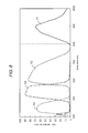
- FIG. 7 is a graph illustrating an example of sensor sensitivity of the image sensor
- FIG. 8 is a graph illustrating an example of spectroscopic properties of the four color separation prism
- FIG. 9 is a graph illustrating spectral sensitivity in a case where four image sensors are used.
- FIG. 10 is a block diagram illustrating a configuration of an endoscope system according to the first exemplary embodiment
- FIG. 11 is a schematic view illustrating an image during a dual output mode displayed on a display
- FIG. 12 a schematic view illustrating an image during a superposed output mode displayed on the display
- FIG. 13 is a graph illustrating spectral sensitivity of a three color separation prism according to a comparative example
- FIG. 14 is a view illustrating a structure example of a three color separation prism according to a second exemplary embodiment
- FIG. 15 is a block diagram illustrating a configuration example of an endoscope system according to the second exemplary embodiment
- FIG. 16 is a graph illustrating spectral sensitivity in a case where three image sensors are used and one of the image sensors receives IR and blue light;
- FIG. 17 is a graph illustrating spectral sensitivity in a case where an IR and green color image sensor according to the comparative example receives IR light;
- FIG. 18 is a view illustrating a structure example of a two color separation prism according to a third exemplary embodiment
- FIG. 19 is a block diagram illustrating a configuration example of an endoscope system according to the third exemplary embodiment.
- FIG. 20 is a graph illustrating spectral sensitivity in a case where two image sensors are used.
- FIG. 21 is a graph illustrating spectral sensitivity of a three color separation prism according to the comparative example.
- an indocyamine green (ICG) which is a fluorescent substance is administered into a body, and near infrared light is emitted to an area such as an excessively accumulated tumor (affected area).
- the affected area is lightened so as to image an area including the affected area in some cases. If the ICG is excited by the near infrared light (for example, peak wavelength of 805 nm, 750 to 810 nm), the ICG is a substance which fluoresces using the near infrared light having a longer wavelength (for example, peak wavelength of 835 nm).
- a filter for a red color (R) component, a green color (G) component, a blue color (B) component, and the IR component which are divided into four is disposed on an incident surface of the image sensor. Therefore, if a user tries to obtain desired color reproducibility and resolution, a size of the image sensor has to increase. Consequently, the single board-type camera is less likely to be applied to the endoscope.
- signal strength of the IR component (for example, light having a wavelength of 800 nm or greater) is weak as illustrated in FIG. 13 .
- FIG. 13 is a graph illustrating spectral sensitivity of the triple board-type camera according to a comparative example.
- a vertical axis represents the spectral sensitivity
- a horizontal axis represents a wavelength.
- the spectral sensitivity corresponds to a ratio between a light quantity of light incident on each prism for the R-component, the G-component, and the B-component, and a light quantity detected by an imaging element corresponding to each prism.
- Waveform h 11 represents the spectral sensitivity of the light having the R-component.
- Waveform h 12 represents the spectral sensitivity of the light having the G-component.
- Waveform h 13 represents the spectral sensitivity of the light having the B-component.
- Waveform h 11 also includes represents the spectral sensitivity of the light having the IR component.
- the image sensor which receives the light having the R-component can acquire the light having the IR component.
- the spectral sensitivity of the IR component (for example, component having a wavelength of 800 nm or greater) is lower than the spectral sensitivity of the light having the R-component, the G-component, and the B-component. If the signal strength of the IR component is weak, an image (IR image) obtained by the IR component is unclear. Accordingly, it is preferable to increase the signal strength of the IR component so that the image (IR image) obtained by the IR component becomes clearer.
- a blue color separation prism is normally disposed in the three color separation prism, as a prism on an object side on the light is incident.
- the reason is as follows.
- the blue color component has a shorter wavelength than that of the red color component and the green color component. As the wavelength becomes shorter, the blue color component is less likely to receive the influence of polarized light.
- the endoscope In a case where a four color separation prism is disposed in the endoscope, the endoscope has a limited space for disposing the four color separation prism. Accordingly, it is preferable to devise a method of disposing a prism for each color (orientation for disposing the prism or angle relating to the prism).
- a quadruple board-type camera using a four color separation prism and four image sensors is disposed in a camera head of the endoscope.
- the four color separation prism separates light focused by a relay lens into three primary color light of R-light (R-component), G-light (G-component), and B-light (B-component), and IR light (IR component).
- the IR component includes at least a portion of a wavelength band of 750 nm to 900 nm.
- FIG. 1 is a schematic view illustrating an external configuration of endoscope 10 according to the first exemplary embodiment.
- FIG. 2 is a schematic view illustrating a brief configuration of endoscope 10 .
- Endoscope 10 is a medical instrument which can be handled by a user with one hand.
- endoscope 10 is configured to include scope 11 , mount adapter 12 , relay lens 13 , camera head 14 , operation switch 19 , and light source connector 18 .
- scope 11 is a main portion of a hard endoscope, which is to be inserted into the body, and is an elongated light guide member which can guide light from a terminal end to a front end.
- Scope 11 has imaging window 11 z in the front end, and has an optical fiber through which an optical image incident from imaging window 11 z is transmitted, and an optical fiber which guides light L introduced from light source connector 18 to the front end.
- imaging window 11 z optical materials such as optical glass and optical plastic are used.
- Mount adapter 12 is a member for mounting scope 11 on camera head 14 .
- Various scopes 11 can be mounted on mount adapter 12 so as to be detachable therefrom.
- Light source connector 18 introduces illumination light for illuminating an area inside a body (affected area or the like) from a light source device (not illustrated).
- the illumination light includes visible light and IR light.
- the light introduced to light source connector 18 is guided to the front end of scope 11 through scope 11 , and is emitted to the area inside the body (affected area or the like) from imaging window 11 z .
- the light source is an LED light source.
- the light source may be a xenon lamp or a halogen lamp.
- Light source connector 18 is mounted on scope 11 via a connector between scope 11 and light source connector 18 .
- the connector internally has a mirror (not illustrated). The light guided from light source connector 18 is reflected on the mirror, and is emitted to the affected area after moving forward to the front end side of scope 11 .
- Relay lens 13 focuses an optical image transmitted through scope 11 onto an imaging surface.
- Relay lens 13 has one or more lenses.
- relay lens 13 may move the lens so as to perform focus adjustment and magnification adjustment.
- Camera head 14 has a housing which can be gripped by a user (for example, a doctor or an assistant) with a hand when in use (for example, during surgery), and internally has four color separation prism 20 (refer to FIGS. 5 and 6 ), four image sensors 230 , 231 , 232 , and 233 (refer to FIGS. 5 and 6 ), and electronic board 250 (refer to FIG. 10 ).
- Four color separation prism 20 is a quadruple board-type prism that separates light focused by relay lens 13 into three primary color light of R-light (R-component), G-light (G-component), and B-light (B-component), and IR light (IR component).
- R-component R-light
- G-component G-light
- B-component B-light
- IR component IR component
- Image sensors 230 to 233 convert the optical image separated by four color separation prism 20 and formed on each imaging surface into an image signal (electric signal).
- an image sensor such as a charge coupled device (CCD) or complementary metal oxide semiconductor (CMOS) is used.
- CCD charge coupled device
- CMOS complementary metal oxide semiconductor
- Four image sensors 230 to 233 are dedicated sensors which respectively receive the light of the IR component, the B-component, the R-component, and the G-component. Therefore, unlike a single board-type camera which receives the light of the IR component, the R-component, the G-component, and the B-component by using a single image sensor, a small size image sensor can be employed as an individual image sensor. For example, an image sensor whose size is 1/2.86 inches is used.
- circuits including a signal output circuit for outputting a signal by using a low volt digital signal (LVDS) and a timing generator (TO) circuit (TO circuit) are mounted on electronic board 250 (simply referred to as a board) (refer to FIG. 10 ).
- LVDS low volt digital signal
- TO timing generator
- the signal output circuit outputs an RGB signal and an IR signal of an image captured by each of image sensors 230 to 233 , as a pulse signal by using the low volt digital signal (LVDS).
- the TG circuit supplies a timing signal (synchronizing signal) to each unit inside camera head 14 .
- the RGB signal includes at least one of the R-component, the G-component, and the B-component. Without being limited to the RGB signal, other color image signals (for example, HSV, YUV, YcCbCr, or YpbPr) may be output.
- Signal cable 14 z for transmitting the image signal to camera control unit (CCU) 30 (to be described later) is mounted on camera head 14 .
- FIG. 3 is a view illustrating camera head 14 and relay lens 13 which are coupled to each other.
- An end surface of four color separation prism 20 incorporated in camera head 14 is disposed so as to face flange surface 13 v of relay lens 13 .
- Relay lens 13 forms an image on image sensors 230 to 233 inside camera head 14 by using the light incident from a subject through scope 11 mounted on mount adapter 12 .
- Relay lens 13 has focus ring 13 y and optical column 13 z .
- One end portion (lower end portion in the drawing) of relay lens 13 is mounted on a mounting target portion of mount adapter 12 .
- the other end portion (upper end portion in the drawing) of relay lens 13 has screw-thread cutter 13 w having a predetermined height (for example, 4 mm).
- Camera head 14 having four color separation prism 20 incorporated therein is screwed into screw-thread cutter 13 w , thereby mounting relay lens 13 on camera head 14 . If relay lens 13 is mounted on camera head 14 by screw-thread cutter 13 w , four color separation prism 20 inside camera head 14 and the lens inside relay lens 13 face each other via a gap. The gap prevents four color separation prism 20 and relay lens 13 from coming into contact with each other.
- camera head 14 and relay lens 13 are coupled to each other in the C-mount.
- the quadruple board-type camera is disposed so as to have this optical path length.
- the light which is guided from a subject by relay lens 13 through scope 11 is focused by relay lens 13 , thereby forming an image on four image sensors 230 to 233 through four color separation prism 20 inside camera head 14 .
- FIGS. 4A and 4B are views illustrating a configuration component and an external configuration of image sensor 230 .
- Four image sensors 230 to 233 have substantially the same specifications. Accordingly, the configuration will be described herein using IR image sensor 230 .
- sensor element 230 y is accommodated inside sensor package 230 w , and is fixed thereto using adhesive 230 v .
- Sensor package glass 230 x is disposed on a front surface of sensor package 230 w .
- Sensor element 230 y receives the light transmitted through sensor package glass 230 x .
- Sensor package 230 w is mounted on sensor board 230 z , and is molded as image sensor 230 .
- image sensor 230 receives the IR light emitted from light emission surface 220 c of IR separation prism (IR color separation prism) 220 , and captures the IR image.
- Image sensors 231 , 232 , and 233 for capturing a visible light image also have the same structure as that of IR image sensor 230 .
- a visible light cut filter for blocking light having the wavelength of 700 nm or smaller is disposed on the front surface of IR image sensor 230 . The visible light cut filter can improve image quality of the IR image.
- FIG. 5 is a view illustrating a first structure example (four color separation prism 20 A) of four color separation prism 20 .
- Four color separation prism 20 A separates incident light guided by relay lens 13 into the light of three primary color light of the R-component, the G-component, and the B-component, and the IR component.
- IR separation prism 220 In four color separation prism 20 A, IR separation prism 220 , blue color separation prism 221 , red color separation prism 222 , and green color separation prism 223 are sequentially assembled in an optical axis direction. This arrangement order is an example, and other arrangement orders may be employed.
- ⁇ 1> ⁇ 2 is satisfied.
- angle ⁇ 1 formed between object side incident surface 220 a of IR separation prism 220 and reflective surface 220 b of IR separation prism 220 is formed to be greater than angle ⁇ 2 formed between an extension line of object side incident surface 220 a of IR separation prism 220 and an extension line of reflective surface 221 b of blue color separation prism 221 . That is, ⁇ 1 > ⁇ 2 is satisfied.
- angle ⁇ 1 represents an angle formed between a straight line parallel to object side incident surface 220 a of IR separation prism 220 and a straight line parallel to reflective surface 220 b .
- angle ⁇ 2 represents an angle formed between the straight line parallel to object side incident surface 220 a of IR separation prism 220 and a straight line parallel to reflective surface 221 b of blue color separation prism 221 .
- IR image sensor 230 is disposed so as to face light emission surface 220 c of IR separation prism 220 .
- Blue color image sensor 231 is disposed so as to face light emission surface 221 c of blue color separation prism 221 .
- Red color image sensor 232 is disposed so as to face light emission surface 222 c of red color separation prism 222 .
- Green color image sensor 233 is disposed so as to face light emission surface 223 c of green color separation prism 223 .
- image sensors 230 to 233 are CCD or CMOS image sensors including respective pixels which are arrayed in a horizontal (H) direction and a vertical (V) direction.
- Image sensors 230 to 233 convert the optical image in which the light separated into each color of IR, R, G, and B forms an image on each imaging surface, into an electric signal.
- IR separation prism 220 the incident light is incident on object side incident surface 220 a of IR separation prism 220 .
- the light reflected on reflective surface 220 b facing object side incident surface 220 a is totally reflected at a boundary of object side incident surface 220 a of IR separation prism 220 , and is incident on IR image sensor 230 after being emitted from light emission surface 220 c facing object side incident surface 220 a .
- IR reflective film 240 is formed on reflective surface 220 b by vapor deposition.
- IR separation prism 220 causes the light of the IR component in the incident light to be reflected thereon, and causes other light (light of the B-component, the R-component, and the G-component) to be transmitted therethrough.
- IR image sensor 230 causes the light reflected on reflective surface 220 b and object side incident surface 220 a to be incident thereon, thereby receiving the light. In this way, IR separation prism 220 is molded so that the light moves forward in IR separation prism 220 .
- blue color separation prism 221 the light (incident light) transmitted through IR separation prism 220 is incident on object side incident surface 221 a of blue color separation prism 221 .
- the light reflected on reflective surface 221 b facing object side incident surface 221 a is totally reflected at a boundary of object side incident surface 221 a of blue color separation prism 221 , and is incident on blue color image sensor 231 after being emitted from light emission surface 221 c facing object side incident surface 221 a .
- blue light reflective film 241 is formed on reflective surface 221 b by vapor deposition.
- Blue color separation prism 221 causes the light of the B-component in the incident light to be reflected thereon, and causes other light (light of the R-component and the G-component) to be transmitted therethrough.
- Blue color image sensor 231 causes the light reflected on reflective surface 221 b and object side incident surface 221 a to be incident thereon, thereby receiving the light.
- blue color separation prism 221 is molded so that the light moves forward in blue color separation prism 221 .
- red color separation prism 222 the light (incident light) transmitted through blue color separation prism 221 is incident on object side incident surface 222 a of red color separation prism 222 .
- the light reflected on reflective surface 222 b facing object side incident surface 222 a is totally reflected at a boundary of object side incident surface 222 a of red color separation prism 222 , and is incident on red color image sensor 232 after being emitted from light emission surface 222 c facing object side incident surface 222 a .
- red light reflective film 242 is formed on reflective surface 222 b by vapor deposition.
- Red color separation prism 222 causes the light of the R-component in the incident light to be reflected thereon, and causes other light (light of the G-component) to be transmitted therethrough.
- Red color image sensor 232 causes the light reflected on reflective surface 222 b and object side incident surface 222 a to be incident thereon, thereby receiving the light.
- red color separation prism 222 is molded so that the light moves forward in red color separation prism 222 .
- green color separation prism 223 the light (incident light) transmitted through red color separation prism 222 is incident on object side incident surface 223 a of green color separation prism 223 , and is incident on green color image sensor 233 after being emitted from light emission surface 223 c facing object side incident surface 223 a .
- green color separation prism 223 is molded so that the light moves forward in green color separation prism 223 .
- the number of light reflected times in each color separation prism is normally an even number of times (for example, twice, 0 times). The reason is that mirror image information is output from the color separation prism in a case where the number of reflected times is an odd number of times.
- IR separation prism 220 and IR image sensor 230 are disposed on opposite sides across incident light center line ILC.
- Incident light center line ILC represents an optical path of the light in a plurality of incident rays which are vertically incident on object side incident surface 220 a of IR separation prism 220 .
- the light is transmitted through IR separation prism 220 , is transmitted through blue color separation prism 221 , is transmitted through red color separation prism 222 , is incident on center Cl (refer to FIG. 4B ) on a light receiving surface of green color image sensor 233 facing light emission surface 233 c of green color separation prism 223 .
- IR image sensor 230 is disposed on an upper side (refer to FIG. 5 ) from incident light center line ILC, and blue color image sensor 231 is disposed on a lower side (refer to FIG. 5 ) from incident light center line ILC.
- Red color separation prism 222 and red color image sensor 232 are arranged between blue color separation prism 221 and blue color image sensor 231 , and green color separation prism 223 and green color image sensor 233 .
- red color separation prism 222 and red color image sensor 232 are disposed on the lower side from incident light center line ILC, in view of a layout space inside camera head 14 (refer to FIG. 5 ). If the layout position of red color image sensor 232 is disposed on the upper side from incident light center line ILC, due to a limited space inside camera head 14 , the layout position of red color image sensor 232 overlaps the layout position of IR image sensor 230 or the layout position of green color separation prism 223 . Accordingly, it becomes difficult to physically dispose these sensors.
- endoscope 10 Since red color image sensor 232 is disposed on the lower side from incident light center line ILC, endoscope 10 enables four color separation prism 20 A to be disposed inside the limited layout space. Therefore, it is possible to miniaturize camera head 14 which accommodates the four color separation prism.
- IR separation prism 220 is disposed to be closest to the object side among the respective color separation prisms. That is, IR separation prism 220 is disposed closer to the object side than other color separation prisms (blue color separation prism 221 , red color separation prism 222 , and green color separation prism 223 ) when receiving the light incident from the affected area.
- IR image sensor 230 disposed to face light emission surface 220 c of IR separation prism 220 can receive the IR light as much as possible.
- the IR light fluoresces with lower light intensity compared to the light of the B-component, the R-component, and the G-component. That is, with regard to the light incident on four color separation prism 20 A, four color separation prism 20 A can restrain a light quantity of the IR component received by IR image sensor 230 from decreasing due to prism transmission.
- Four color separation prism 20 A can acquire a clearly captured image of the affected area, based on fluorescence generated by the light of the IR component being emitted to a fluorescent substance (for example, ICG) inside the affected area.
- a fluorescent substance for example, ICG
- blue color separation prism 221 is disposed closer to the object side, subsequently (secondly) to IR separation prism 220 .
- the reason is that the B-component has a shorter wavelength than that of the R-component and the G-component. As the wavelength becomes shorter, each color separation prism receives less influence of polarized light which can occur when the light is reflected. Therefore, since in four color separation prism 20 A, blue color separation prism 221 is disposed closer to the object side than red color separation prism 222 and green color separation prism 223 , it is possible to restrain the influence of the polarized light.
- Blue color separation prism 221 is disposed closer to the object side than IR separation prism 220 .
- spectral transmittance becomes higher on a high wavelength side (that is, the green color component side and the red color component side) in FIG. 8 . Accordingly, a reflected amount of the IR light increases in blue light reflective film 241 , thereby decreasing the light quantity of the IR light incident on IR separation prism 220 disposed in the rear stage.
- endoscope 10 since IR separation prism 220 is disposed closer to the object side than blue color separation prism 221 as illustrated in FIG. 5 , an image obtained by the IR light can have higher image quality compared to a case where blue color separation prism 221 is disposed closer to the object side than IR separation prism 220 . That is, based on the fluorescence of the ICG, endoscope 10 can acquire an image which clearly shows a state of the affected area.
- Green color separation prism 223 and green color image sensor 233 are disposed so as to receive the light by setting incident light center line ILC as substantially the center. In this manner, without a need to dispose a green light reflective film, it is possible to simplify a shape of green color separation prism 223 . Accordingly, it is possible to easily design a configuration element relating to the G-component.
- the order of green color separation prism 223 is the last to receive the incident light. That is, is preferable that green color separation prism 223 is disposed farthest from the object side among a plurality of color separation prisms.
- the G-component is included in an intermediate wavelength band between the B-component and the R-component.
- IR reflective film 240 In a front stage from green color separation prism 223 , IR reflective film 240 , blue light reflective film 241 , and red light reflective film 242 can easily block light components other than the G-component.
- These reflective films can be designed as a low pass filter (LPF) or a high pass filter (HPF). Accordingly, it is possible to easily design filters.
- FIG. 6 a view illustrating a second structure example (four color separation prism 20 B) of four color separation prism 20 .
- four color separation prism 20 B description of the same structure as that of four color separation prism 20 A illustrated in FIG. 5 will be omitted or simplified.
- IR image sensor 230 causes the light reflected on reflective surface 220 b and object side incident surface 220 a to be incident thereon, thereby receiving the light.
- Angle ⁇ 1 illustrated in FIG. 6 is smaller than angle ⁇ 1 illustrated in FIG. 5 . Accordingly, a reflective angle (angle formed between a line perpendicular to reflective surface 220 b and a light ray reflected from reflective surface 220 b ) on reflective surface 220 b of IR separation prism 220 becomes smaller than that in a case illustrated in FIG. 5 .
- a reflective angle (angle formed between a line perpendicular to object side incident surface 220 a and a light ray reflected from object side incident surface 220 a ) on object side incident surface 220 a also becomes smaller than that in the case illustrated in FIG. 5 .
- an orientation of the light ray reflected on object side incident surface 220 a is close to an orientation of the light ray moving forward in green color separation prism 223 , and a position of IR image sensor 230 is close to a position of green color image sensor 233 .
- IR separation prism 220 is designed so that a distance between object side incident surface 220 a and light emission surface 220 c is longer than that in a case illustrated in FIG. 5 . Accordingly, reflective surface 220 b of IR separation prism 220 is bent along the light ray reflected on object side incident surface 220 a , and thus, a shape of IR separation prism 220 is complicated. Reflective surface 220 b requires polishing in order to transmit the light components other than the IR component. However, if reflective surface 220 b is bent, reflective surface 220 b is less likely to be polished.
- a front end portion of IR separation prism 220 (end portion including light emission surface 220 c and IR image sensor 230 ) is formed close to green color separation prism 223 side. Accordingly, compared to the case illustrated in FIG. 5 , it becomes more difficult to dispose red color separation prism 222 between the front end portion of IR separation prism 220 and green color separation prism 223 . Therefore, red color separation prism 222 together with blue color separation prism 221 is disposed on the lower side from incident light center line ILC.
- Blue color image sensor 231 causes the light reflected on reflective surface 221 b and object side incident surface 221 a to be incident thereon, thereby receiving the light.
- Angle ⁇ 2 illustrated in FIG. 6 is larger than angle ⁇ 2 illustrated in FIG. 5 . Accordingly, a reflective angle (angle formed between a line perpendicular to reflective surface 221 b and a light ray reflected from reflective surface 221 b ) on reflective surface 221 b of blue color separation prism 221 becomes larger than that in the case illustrated in FIG. 5 .
- a reflective angle (angle formed between a line perpendicular to object side incident surface 221 a and a light ray reflected from object side incident surface 221 a ) on object side incident surface 221 a also becomes larger than that in the case illustrated in FIG. 5 .
- the light reflected on object side incident surface 221 a and emitted from light emission surface 221 c is close to the incident surface of four color separation prism 20 B (that is, object side incident surface 220 a of IR separation prism 220 ), and is received in an end portion on object side incident surface 220 a in blue color image sensor 231 .
- Design is made so as to satisfy the following condition.
- the light reflected on reflective surface 221 b of blue color separation prism 221 does not go beyond a range of object side incident surface 221 a , and is reflected on object side incident surface 221 a .
- the light is totally reflected on object side incident surface 221 a.
- IR image sensor 230 may output an electric signal having each pixel value (signal level) without any change. However, IR image sensor 230 may output the electric signal having a pixel value subjected to H/V pixel addition processing by performing the H/V pixel addition processing for adding pixel values of pixels adjacent in a horizontal (H) or vertical (V) direction.
- IR image sensor 230 is independently disposed according to endoscope 10 of the present exemplary embodiment. Accordingly, compared to a case in the related art, the pixel value of the IR component can be obtained as much as approximately 3 times to 12 times.
- each signal level of the R-component, the G-component, and the B-component becomes substantially the same as a signal level of the IR component. Accordingly, the RGB image and the IR image are likely to be visible.
- the RGB image is obtained using at least one signal of the R-component, the G-component, and the B-component.
- the IR image is obtained using the signal of the IR component.
- FIG. 7 is a graph illustrating sensor sensitivity of image sensor 230 .
- the vertical axis represents the sensor sensitivity.
- the sensor sensitivity corresponds to a ratio of the light quantity detected by image sensor 230 with respect to the light quantity of the light incident on image sensor 230 .
- the sensor sensitivity illustrated in FIG. 7 is an absolute value in a case where the sensor sensitivity in the light wavelength of 510 nm is set to value 1.
- the horizontal axis represents the light wavelength in units of nm.
- Waveform gh 1 represents properties of the sensor sensitivity of image sensor 230 according to the present exemplary embodiment with respect to the light wavelength.
- Waveform gh 2 represents properties of the sensor sensitivity of an image sensor according to a comparative example (in the related art) with respect to the light wavelength.
- the sensor sensitivity in the light wavelength of 830 nm is value 0.551, which is approximately 55% compared to a case of the light wavelength of 510 nm.
- the sensor sensitivity in the light wavelength of 830 nm is value 0.298, which is approximately 30% compared to the case of the light wavelength of 510 nm.
- the wavelength band of 830 nm is the wavelength band of the fluorescence using the ICG.
- the sensor sensitivity of image sensor 230 is substantially the same sensitivity in a blue light region (B-component) of 400 nm to 500 nm.
- the sensor sensitivity of image sensor 230 becomes higher in a green light region (G-component) of 500 nm to 600 nm and a red light region (R-component) of 600 nm to 700 nm.
- the sensor sensitivity of image sensor 230 is high even in a near infrared light (IR light) region (IR component) of 750 nm to 900 nm.
- IR light near infrared light
- an image sensor having the properties of the sensor sensitivity illustrated by waveform gh 1 is referred to as a high sensitivity sensor.
- An image sensor having the properties of the sensor sensitivity illustrated by waveform gh 2 is referred to as a normal sensitivity sensor.
- the high sensitivity sensor has high sensitivity on the long wavelength side, compared to the normal sensitivity sensor.
- the high sensitivity sensor is used for image sensors 230 to 233 .
- the high sensitivity sensor is used for red color, green color, and blue color image sensors 231 to 233
- the normal sensitivity sensor may be used.
- FIG. 8 is a graph illustrating an example of spectroscopic properties (spectral transmittance) of four color separation prism 20 .
- the vertical axis in FIG. 8 represents each spectral transmittance (%), and corresponds to a ratio of the light quantity of the light incident on image sensors 230 to 233 in each prism with respect to the light quantity of the light incident on each prism.
- the horizontal axis in FIG. 8 represents the wavelength (nm) of the light incident on respective image sensors 230 to 233 .
- the light quantity of the light incident on image sensors 230 to 233 in each prism corresponds to the light quantity of the light emitted from each prism.
- waveform h 1 (solid line) illustrates the spectroscopic properties of the light of the IR component which is incident on IR image sensor 230 .
- Transmittance of the light of the IR component which is incident on IR image sensor 230 in the light incident on four color separation prism 20 has a peak waveform whose wavelength is near 900 nm in the wavelength of 800 to 1,000 nm and whose transmittance is approximately 70%.
- Waveform h 2 (one-dot chain line) illustrates the spectroscopic properties of the light of the R-component which is incident on red color image sensor 232 .
- Transmittance of the light of the R-component which is incident on red color image sensor 232 has a peak waveform whose wavelength is near 600 nm and whose transmittance is approximately 80%.
- Waveform h 3 (dotted line) illustrates the spectroscopic properties of the light of the B-component which is incident on blue color image sensor 231 .
- Transmittance of the light of the B-component which is incident on blue color image sensor 231 has a peak waveform whose wavelength is near 450 nm and whose transmittance exceeds 60%.
- Waveform h 4 (two-dot chain line) illustrates the spectroscopic properties of the light of the G-component which is incident on green color image sensor 233 .
- Transmittance of the light of the G-component which is incident on green color image sensor 233 has a peak waveform whose wavelength is near 530 nm and whose transmittance is approximately 90%.
- any transmittance of the light of the IR component, the R-component, the B-component, and the G-component which are separated by four color separation prism 20 exceeds 60%. Therefore, each pixel value of the IR component, the R-component, the B-component, and the G-component can be suitably obtained, and a signal of the IR component may not be greatly amplified. In this manner, in a case where the affected area is imaged, color reproducibility of a captured image including the IR component is improved.
- FIG. 9 is a graph illustrating the spectral sensitivity in a case where four image sensors 230 to 233 are used.
- the vertical axis in FIG. 9 represents the spectral sensitivity in units of percentage.
- the horizontal axis in FIG. 9 represents a wavelength (nm) of the light incident on respective image sensors 230 to 233 .
- the spectral sensitivity corresponds to the light quantity of the light having each wavelength detected by image sensors 230 to 233 with respect to the light quantity of the light incident on four color separation prism 20 .
- the spectral sensitivity is obtained in such a way that the sensor sensitivity illustrated in FIG. 7 is multiplied by the spectral transmittance illustrated in FIG. 8 .
- the spectral sensitivity is one of performance indicators of the quadruple board-type camera inside camera head 14 .
- the maximum value of the sensor sensitivity of the normal sensitivity sensor illustrated by waveform gh 6 in FIG. 7 is set to value 1.
- value 1 is multiplied by the spectral transmittance of four color separation prism 20 . Therefore, the spectral sensitivity of 100% indicates a state where the spectral transmittance of four color separation prism 20 is 100% and the sensor sensitivity of the normal sensitivity sensor is the maximum.
- the spectral sensitivity illustrated in FIG. 9 has each high value in a blue light region, a green light region, a red light region, and a near infrared light region, when the light passes through four color separation prism 20 .
- a peak value of the spectral sensitivity in the green light region is approximately 90% (refer to waveform br 2 ).
- a peak value of the spectral sensitivity in the near infrared light region is approximately 48%, and has a value equal to or greater than 40% of the peak value (90%) of the spectral sensitivity in the green light region (530 nm) (refer to waveform br 1 ). Therefore, the spectral sensitivity in the IR region is obtained so as to have a desired high value.
- the peak value of the spectral sensitivity in the green light region corresponds to the maximum value of the spectral sensitivity in all of the wavelength bands including the visible light band of the RGB.
- the peak value of the spectral sensitivity in the near infrared light region is approximately half (approximately 24%) of the spectral sensitivity of the quadruple board-type camera according to the present exemplary embodiment.
- the quadruple board-type camera included in camera head 14 has a peak value of 40% equal to or greater than a peak value in the visible light region (here, a peak value in the green light region). That is, the quadruple board-type camera has high sensitivity for the IR light.
- the sensor sensitivity of the image sensors illustrated in FIGS. 7 to 9 , the spectroscopic properties of four color separation prism 20 , and the spectral sensitivity of the quadruple board-type camera are examples, the endoscope system may have other properties.
- FIG. 10 is a block diagram illustrating a configuration of endoscope system 5 according to the first exemplary embodiment.
- Endoscope system 5 is configured to include endoscope 10 , CCU 30 , and display 40 .
- CCU 30 is an example of a processor.
- Display 40 is an example of a display device.
- Camera head 14 of endoscope 10 has four color separation prism 20 , and image sensors 230 , 231 , 232 , and 233 which are described above.
- camera head 14 further has respective element drivers 141 i , 141 r , 141 b , and 141 g , drive signal generator 142 , synchronizing signal generator 143 , and signal output 145 .
- Element driver 141 i drives image sensor 230 in accordance with a drive signal.
- Element driver 141 r drives image sensor 231 in accordance with a drive signal.
- Element driver 141 b drives image sensor 232 in accordance with a drive signal.
- Element driver 141 g drives image sensor 233 in accordance with a drive signal.
- Drive signal generator 142 generates the drive signal for respective element drivers 141 i , 141 r , 141 b , and 141 g .
- Synchronizing signal generator 143 corresponds to a function of a timing generator (TG) circuit, and supplies a synchronizing signal (timing signal) to drive signal generator 142 .
- Signal output 145 transmits an electric signal output from image sensors 230 , 231 , 232 , and 233 to CCU 30 via signal cable 14 z by using an LVDS method, for example.
- Signal output 145 may transmit a synchronizing signal output from synchronizing signal generator 143 to CCU 30 via signal cable 14 z .
- Signal output 145 may transmit an operation signal of operation switch 19 to CCU 30 via signal cable 14 z .
- Signal output 145 corresponds to a function of a signal output circuit.
- CCU 30 fulfills various functions by executing a program stored in an internal or external memory (not illustrated) of CCU 30 .
- the various functions include each function of RGB signal processor 22 , IR signal processor 23 , and output 28 .
- RGB signal processor 22 converts the electric signals of the B-component, the R-component, and the G-component which are output from image sensors 231 , 232 , and 233 , into video signals which can be displayed on display 40 , and outputs the video signals to output 28 .
- IR signal processor 23 converts the electric signal of the IR component output from image sensor 230 into a video signal, and outputs the video signal to output 28 .
- IR signal processor 23 may have gain adjuster 23 z .
- Gain adjuster 23 z adjusts an amplification degree (gain) when the electric signal of the IR component which is output from IR image sensor 230 is converted into the video signal.
- gain adjuster 23 z may adjust signal strength of the video signal of the RGB component so as to be substantially the same as signal strength of the video signal of the IR component.
- Gain adjuster 23 z enables a user to reproduce the IR image for the RGB image with optional intensity.
- RGB signal processor 22 may adjust the amplification degree of the electric signal of the RGB component.
- RGB signal processor 22 and IR signal processor 23 receives the synchronizing signal output from synchronizing signal generator 143 , and are operated in accordance with the synchronizing signal. In this manner, an image (video image) of each RGB color component and an image of the IR component are adjusted so as not to cause a time lag.
- output 28 outputs at least any one of the video signal of each RGB color component and the video signal of the IR component, to display 40 .
- output 28 outputs the video signal, based on any one of a dual output mode and a superposed output mode.
- output 28 simultaneously outputs RGB image G 1 and IR image G 2 (refer to FIG. 11 ) using different screens.
- the dual output mode enables a user to observe the affected area tg by comparing the RGB image and the IR image with each other using the different screens.
- output 28 outputs synthesized image GZ in which the RGB image and the IR image are superposed on each other (refer to FIG. 12 ).
- the superposed output mode enables a user to clearly observe affected area tg which fluoresces due to the ICG and the IR light serving as illumination light inside the RGB image.
- RGB signal processor 22 IR signal processor 23 , and output 28 perform processing using software by the processor inside CCU 30 cooperating with the memory.
- all of these may be configured to respectively include dedicated hardware.
- display 40 Based on the video signal output from CCU 30 , display 40 causes a screen to display an image of an object such as affected area tg which is imaged by endoscope 10 and which is output from CCU 30 .
- display 40 divides the screen into a plurality of screens (for example, into two screens), and causes each screen to display RGB image G 1 and IR image G 2 side by side (refer to FIG. 11 ).
- display 40 causes one screen to display synthesized image GZ in which RGB image G 1 and IR image G 2 are superposed on each other (refer to FIG. 12 ).
- an indocyamine green (ICG) which is a fluorescent substance may be administered into the body, and near infrared light may be emitted to an area such as an excessively accumulated tumor (affected area).
- the affected area may be lightened so as to image the affected area.
- Light L which is introduced into light source connector 18 by a user operating operation switch 19 is guided to a front end side of scope 11 , and is emitted from imaging window 11 z , thereby illuminating an area around the affected area which includes the affected area.
- the light reflected on the affected area and the like is guided to a rear end side of scope 11 through imaging window 11 z , is focused by relay lens 13 , and is incident on four color separation prism 20 of camera head 14 .
- the light of the IR component separated by IR separation prism 220 in the incident light forms an image as an optical image of the infrared light component in IR image sensor 230 .
- the light of the B-component separated by blue color separation prism 221 forms an image as an optical image of the blue color component in blue color image sensor 231 .
- the light of the R-component separated by red color separation prism 222 forms an image as an optical image of the red color component in red color image sensor 232 .
- the light of the G-component separated by green color separation prism 223 forms an image as an optical image of the green color component in green color image sensor 233 .
- the electric signal of the IR component which is converted by IR image sensor 230 is converted into the video signal by IR signal processor 23 inside CCU 30 , and is output to output 28 .
- Each electric signal of the B-component, the R-component, and the G-component which are respectively converted by visible light image sensors 231 , 232 , and 233 are converted into each video signal by RGB signal processor 22 inside CCU 30 , and is output to output 28 .
- the video signal of the IR component and the respective video signals of the B-component, the R-component, and the G-component are synchronized with each other, and are output to display 40 .
- FIG. 11 is a schematic view illustrating an image during the dual output mode displayed on display 40 .
- RGB image G 1 is a color image by imaging the area including affected area tg after emitting the visible light thereto.
- IR image G 2 is a black and white image (any optional color can be set) by imaging the area including affected area tg after emitting the IR light thereto.
- display 40 displays synthesized image GZ 1 in which RGB image G 1 and IR image G 2 are superposed on (synthesized with) each other.
- FIG. 12 a schematic view illustrating an image during the superposed output mode displayed on display 40 .
- endoscope 10 includes four color separation prism 20 that includes the first color separation prism, the second color separation prism, the third color separation prism, and the fourth color separation prism which respectively separate the light reflected from the affected area into the first color component, the second color component, the third color component, and the fourth color component which are any one of the blue color component, the red color component, the green color component, and the IR component, the first color image sensor that is installed in the first color separation prism, and that converts the separated first color component into the electric signal, the second color image sensor that is installed in the second color separation prism, and that converts the separated second color component into the electric signal, the third color image sensor that is installed in the third color separation prism, and that converts the separated third color component into the electric signal, the fourth color image sensor that is installed in the fourth color separation prism, and that converts the separated fourth color component into the electric signal, and signal output 145 that outputs the color image signal and the IR signal from the respective converted electric signals.
- the first color separation prism, the second color separation prism, the third color separation prism, and the fourth color separation prism are sequentially disposed from the object side when receiving the light incident from the affected area.
- the first color image sensor is disposed opposite to the second color image sensor and the third color image sensor across the incident ray which is incident vertically to the object side incident surface of the first color separation prism.
- the incident ray is incident light center line ILC.
- endoscope 10 can usefully and efficiently dispose each color separation prism (particularly, the third color separation prism), and can easily realize four color separation prism 20 .
- the layout space for the third color separation prism is small on the upper side of the incident ray (one region with respect to the incident ray).
- the layout space can be secured on the lower side of the center line of the incident ray (the other region with respect to the incident ray). Accordingly, four color separation prism 20 can be mounted on endoscope 10 , and each independent image sensor can receive each color component separated by each color separation prism. Therefore, the light strength of each color component is likely to be secured.
- endoscope 10 improves image quality by adding the infrared light component to the image.
- Endoscope 10 can adjust color balance by independently controlling each color component, and can improve color reproducibility of each color component.
- camera head 14 includes a three color separation prism and three image sensors. The IR light is separated using the blue color separation prism, and is received by the image sensor.
- FIG. 14 is a view illustrating a structure example of three color separation prism 20 A according to the second exemplary embodiment.
- Three color separation prism 20 A separates the incident light guided by relay lens 13 into the R-light, G-light, B-light, and IR light.
- IR and blue color separation prism 320 In three color separation prism 20 A, IR and blue color separation prism 320 , red color separation prism 321 , and green color separation prism 322 are sequentially assembled in the optical axis direction.
- IR and blue color image sensor 330 is disposed to face light emission surface 320 c of IR and blue color separation prism 320 .
- Red color image sensor 331 is disposed to face light emission surface 321 c of red color separation prism 321 .
- Green color image sensor 332 is disposed to face light emission surface 322 c of green color separation prism 322 .
- image sensors 330 to 332 are CCD or CMOS image sensors including respective pixels which are arrayed in a horizontal (H) direction and a vertical (V) direction.
- Image sensors 330 to 332 convert the optical image in which the light separated into each color of IR, B, R, and G forms an image on each imaging surface, into the electric signal.
- the IR light is detected by IR and blue color image sensor 330 , and thus, the IR light glows in a blue color.
- IR and the blue color separation prism 320 the incident light is incident on incident surface 320 a of IR and the blue color separation prism 320 .
- the light reflected on reflective surface 320 b facing incident surface 320 a is totally reflected at a boundary of incident surface 320 a of IR and blue color separation prism 320 , and is incident on IR and blue color image sensor 330 after being emitted from light emission surface 320 c facing incident surface 320 a .
- IR and blue light reflective film 340 is formed on reflective surface 320 b by vapor deposition.
- IR and blue color separation prism 320 causes the light of the IR and blue color component in the incident light to be reflected thereon, and causes other light (light of the R-component and the G-component) to be transmitted therethrough.
- IR and blue color image sensor 330 causes the light reflected on reflective surface 320 b and incident surface 320 a to be incident thereon, thereby receiving the light. In this way, IR and blue color separation prism 320 is molded so that the light moves forward in IR and blue color separation prism 320 .
- red color separation prism 321 the light (incident light) transmitted through IR and blue color separation prism 320 is incident on incident surface 321 a of red color separation prism 321 .
- the light reflected on reflective surface 321 b facing incident surface 321 a is totally reflected at a boundary of incident surface 321 a of red color separation prism 321 , and is incident on red color image sensor 331 after being emitted from light emission surface 321 c facing incident surface 321 a .
- red light reflective film 341 is formed on reflective surface 321 b by vapor deposition.
- Red color separation prism 321 causes the light of the R-component in the incident light to be reflected thereon, and causes other light (light of the G-component) to be transmitted therethrough.
- Red color image sensor 331 causes the light reflected on reflective surface 321 b and incident surface 321 a to be incident thereon, thereby receiving the light.
- red color separation prism 321 is molded so that the light moves forward in red color separation prism 321 .
- green color separation prism 322 the light (incident light) transmitted through red color separation prism 321 is incident on incident surface 322 a of green color separation prism 322 , and is incident on green color image sensor 332 after being emitted from light emission surface 322 c facing incident surface 322 a .
- green color separation prism 322 is molded so that the light moves forward in green color separation prism 322 .
- an optical distance (optical path length) from flange surface 13 v of relay lens 13 to image sensors 330 to 332 is set to 17.526 mm in a case of the C-mount.
- a refractive index of three color separation prism 20 A may be the same value as “1.8” which is a refractive index of four color separation prism 20 .
- the refractive index of three color separation prism 20 A may be a value of the refractive index which is slightly smaller than that of the quadruple board-type camera, for example, “1.7”. Compared to the quadruple board-type camera, the refractive index is lowered to a slightly smaller value. In this manner, an actual distance (length) of the triple board-type camera is shortened.
- FIG. 15 is a block diagram illustrating a configuration example of endoscope system 5 A according to the second exemplary embodiment.
- the endoscope system according to the second exemplary embodiment has substantially the same configuration as that according to the first exemplary embodiment.
- the same reference numerals will be given to the same configuration elements as those according to the first exemplary embodiment, and description thereof will be omitted or simplified.
- a configuration and an operation which are different from those according to the first exemplary embodiment will be mainly described.
- three element driver 241 ib , element driver 241 r , and element driver 241 g are mounted on electronic board 250 .
- Element driver 241 ib drives IR and blue color image sensor 330 in accordance with a drive signal.
- Element driver 241 r drives red color image sensor 331 in accordance with a drive signal.
- Element driver 241 g drives green color image sensor 332 in accordance with a drive signal.
- Drive signal generator 142 generates the drive signals for each of element drivers 241 ib , 241 r , and 241 g.
- Signal output 145 transmits the electric signal output from image sensors 330 , 331 , and 332 to CCU 30 A. According to the present exemplary embodiment, unlike the first exemplary embodiment, signal output 145 transmits the signal of the R-component (R-signal), the signal of the G-component (G-signal) and the signal (BIR signal) including at least one of the B-component and the IR component, to CCU 30 A.
- R-signal the signal of the G-component
- BIR signal including at least one of the B-component and the IR component
- CCU 30 A includes R-signal processor 261 for converting the R-signal into a video signal, G-signal processor 262 for converting the G-signal into a video signal, and BIR signal processor 263 for converting the BIR signal into a video signal.
- BIR signal processor 263 includes gain adjuster 23 z .
- CCU 30 A is the same as CCU 30 except for a configuration and an operation of the signal processor.
- FIG. 16 is a graph illustrating spectral sensitivity in a case where three image sensors 330 , 331 , and 332 are used and one image sensor 330 receives the IR and blue color light.
- the vertical axis in FIG. 16 represents the spectral sensitivity in units of percentage.
- the horizontal axis in FIG. 16 represents a wavelength (nm) of the light incident on respective image sensors 330 to 332 .
- the spectral sensitivity corresponds to the light quantity of the light having each wavelength detected by image sensors 330 to 332 with respect to the light quantity of the light incident on three color separation prism 20 A.
- the spectral sensitivity is obtained in such a way that the sensor sensitivity illustrated in FIG.
- the spectral transmittance of three color separation prism 20 A is the same as the spectral transmittance of four color separation prism 20 according to the first exemplary embodiment, for example.
- the spectral sensitivity is one of performance indicators of the triple board-type camera inside camera head 14 .
- IR and blue color image sensor 330 receives the light in the blue light region and the IR light through IR and the blue color separation prism 320 .
- the high sensitivity sensor illustrated in the first exemplary embodiment is used.
- red color image sensor 331 and green color image sensor 332 the high sensitivity sensor may be used, or the normal sensitivity sensor may be used.
- FIG. 16 illustrates the spectral sensitivity (refer to waveform br 3 ) in a case of using the high sensitivity sensor and the spectral sensitivity (refer to waveform br 4 ) in a case of using the normal sensitivity sensor. Since endoscope 10 uses the high sensitivity sensor, the spectral sensitivity in the IR region can be improved.
- a peak value of the spectral sensitivity near the wavelength of 580 nm in the green light region which is received by green color image sensor 332 is approximately 94%.
- a peak value of the spectral sensitivity near the wavelength of 830 nm in the IR region is approximately 40%. Therefore, the peak value of the spectral sensitivity in the IR region is approximately 42.5% (40%/94%) of the peak value of the spectral sensitivity in the visible light region (here, the wavelength of 580 nm), that is, 40% or greater. In this manner, the spectral sensitivity in the IR region can be obtained as a desired high value.
- FIG. 17 is a graph illustrating spectral sensitivity in a case where IR and green color image sensor 332 x (not illustrated) receives the IR light, as the comparative example.
- IR and green color image sensor 332 x receives the light in the green light region and the IR light through green color separation prism 322 x .
- the sensor sensitivity of the high sensitivity sensor in the green light region (500 nm to 600 nm) becomes higher than that of the normal sensitivity sensor.
- the spectral sensitivity of the high sensitivity sensor illustrated by waveform gr 1 becomes higher. Therefore, in a case where IR and green color image sensor 332 x is used, the light receiving sensitivity of the IR light can be improved. On the other hand, the color balance in the visible light region is disturbed, and the color reproducibility (distribution of the RGB color component) becomes poor.
- the peak value of the spectral sensitivity of the wavelength of 580 nm in the green light region is approximately 105%.
- the peak value of the spectral sensitivity of the wavelength of 830 nm in the IR region is approximately 40%. That is, the peak value of the spectral sensitivity in the IR region is approximately 38% (40%405%) of the peak value of the spectral sensitivity in the green light region, that is, smaller than 40%. Therefore, as the spectral sensitivity in the IR region, it is difficult to obtain a desired value.
- the wavelength band (for example, the wavelength band of 680 nm) of the excitation light used for fluorescence may be in the red light region, or mat red color components as the color component are present inside the living body.
- the sensor sensitivity of IR and blue color image sensor 330 is that of the high sensitivity sensor. Therefore, compared to the sensor sensitivity of the normal sensitivity sensor, IR and blue color image sensor 330 has a characteristic which is highly sensitive on the long wavelength in the IR light region. Accordingly, endoscope 10 can improve the spectral sensitivity of the IR light, compared to the spectral sensitivity of the RGB light in the visible light region.
- the sensor sensitivity of the high sensitivity sensor is approximately the same as the sensor sensitivity of the normal sensitivity sensor. Therefore, even if the normal sensitivity sensor is replaced with the high sensitivity sensor, endoscope 10 can restrain the color balance from being disturbed in the visible light region.
- the color separation prism may include three color separation prism 20 A which separates the light incident from the object into three color components of the red color component, the green color component, and the blue color component and the infrared light component.
- the image sensor may include three image sensors 330 to 332 which respectively convert the optical image of the three separated color components into the electric signals.
- endoscope 10 can improve the spectral sensitivity in the wavelength region of the infrared light, compared to the spectral sensitivity in the wavelength region of the three primary color light in the visible light region. Accordingly, for example, in a case where the affected area is imaged using the ICG, the fluorescing affected area is easily visible using the IR image by restraining a change in the RGB image showing the entire area including the affected area.
- Endoscope 10 causes one image sensor to detect the blue color component and the infrared light component. In this manner, even if the high sensitivity sensor is used as the image sensor, endoscope 10 can improve the spectral sensitivity of the infrared light component by reducing a change in the spectral sensitivity of the blue color component. Therefore, visibility of the infrared light component can be improved by restraining poor color reproducibility (change in distribution of each color component) of each color component of three primary colors.
- the first exemplary embodiment employs the quadruple board-type prism
- the second exemplary embodiment employs the triple board-type prism.
- a third exemplary embodiment a case of employing a double board-type prism for separating the light into the IR light and the RGB light will be described.
- FIG. 18 is a view illustrating a structure example of two color separation prism 20 B according to the third exemplary embodiment.
- Two color separation prism 20 B separates the incident light guided by relay lens 13 into the light of the RGB component which is the light of the three primary color light, and the light of the IR component.
- IR separation prism 420 and RGB color separation prism 421 are sequentially assembled in the optical axis direction.
- IR image sensor 430 is disposed to face light emission surface 420 c of IR separation prism 420 .
- RGB color image sensor 431 is disposed to face light emission surface 421 c of RGB color separation prism 421 .
- image sensors 430 and 431 are CCD or CMOS image sensors including respective pixels which are arrayed in the horizontal (H) direction and the vertical (V) direction.
- Image sensors 430 and 431 convert the optical image in which the light separated into two colors of the IR and the RGB colors forms an image on each imaging surface, into the electric signal.
- IR separation prism 420 the incident light is incident on incident surface 420 a of IR separation prism 420 .
- the light reflected on reflective surface 420 b facing incident surface 420 a is totally reflected at a boundary of incident surface 420 a of IR separation prism 420 , and is incident on IR image sensor 430 after being emitted from light emission surface 420 c facing incident surface 420 a .
- IR reflective film 440 is formed on reflective surface 420 b by vapor deposition.
- IR separation prism 420 causes the IR light in the incident light to be reflected thereon, and causes other light (light of the RGB component) to be transmitted therethrough.
- IR image sensor 430 causes the light reflected on reflective surface 420 b and incident surface 420 a to be incident thereon, thereby receiving the light. In this way, IR separation prism 420 is molded so that the light moves forward in IR separation prism 420 .
- RGB color separation prism 421 the light (incident light) transmitted through IR separation prism 420 is incident on incident surface 421 a of RGB color separation prism 421 , and is incident on RGB image sensor 431 after being emitted from light emission surface 421 c facing incident surface 421 a .
- RGB color separation prism 421 is molded so that the light moves forward in RGB color separation prism 421 .
- the optical distance (optical path length) from flange surface 13 v of relay lens 13 to image sensors 430 and 431 is also set to 17.526 mm.
- the refractive index of two color separation prism 20 B may be the same as “1.8” which is the refractive index of four color separation prism 20 .
- the refractive index of two color separation prism 20 B may be a smaller refractive index value than that of the quadruple board-type camera or the triple board-type camera, for example, “1.7” or smaller than “1.7”.
- the refractive index has the smaller value. Accordingly, the actual distance (length) of the double board-type camera is shortened.
- FIG. 19 is a block diagram illustrating a configuration example of endoscope system 5 B according to the third exemplary embodiment.
- the endoscope system according to the third exemplary embodiment has substantially the same configuration as that according to the first or second exemplary embodiment.
- the same reference numerals will be given to the same configuration elements as those according to the first or second exemplary embodiment, and description thereof will be omitted or simplified.
- a configuration and an operation which are different from those according to the first or second exemplary embodiment will be described.
- two element driver 341 i and element driver 341 c are mounted on electronic board 250 .
- Element driver 341 i drives IR image sensor 430 in accordance with a drive signal.
- Element driver 341 c drives RGB image sensor 431 in accordance with a drive signal.
- Drive signal generator 142 generates the drive signals for each of element drivers 341 i and 341 c.
- Signal output 145 transmits the electric signal output from image sensors 430 and 431 to CCU 30 .
- a configuration and an operation of CCU 30 are the same as those according to the first exemplary embodiment, and CCU 30 processes the IR signal and the RGB signal.
- FIG. 20 is a graph illustrating spectral sensitivity in a case where two image sensors 430 and 431 are used.
- the vertical axis in FIG. 20 represents the spectral sensitivity in units of percentage.
- the horizontal axis in FIG. 20 represents a wavelength (nm) of the light incident on respective image sensors 430 and 431 .
- the spectral sensitivity corresponds to the light quantity of the light having each wavelength detected by image sensors 430 and 431 with respect to the light quantity of the light incident on two color separation prism 20 B.
- the spectral sensitivity is obtained in such a way that the sensor sensitivity illustrated in FIG. 6 is multiplied by the spectral transmittance of two color separation prism 20 B.
- the spectral transmittance of two color separation prism 20 B is the same as the spectral transmittance of three color separation prism 20 A according to the second exemplary embodiment or the spectral transmittance of four color separation prism 20 according to the first exemplary embodiment, for example.
- the spectral sensitivity is one of performance indicators of the double board-type camera inside camera head 14 .
- IR image sensor 430 receives the IR light through IR separation prism 420 .
- the high sensitivity sensor illustrated in the first exemplary embodiment is used.
- RGB image sensor 431 the high sensitivity sensor may be used, or the normal sensitivity sensor may be used.
- a peak value of the spectral sensitivity near the wavelength of 600 nm in the red light region is approximately 100%.
- a peak value of the spectral sensitivity near the wavelength of 860 nm in the IR region is approximately 47%. Therefore, the peak value of the spectral sensitivity in the IR region is approximately 47% (47%400%) of the peak value of the spectral sensitivity of the wavelength of 600 nm, that is, 47% or greater. Therefore, the spectral sensitivity in the IR region is obtained so as to have a desired high value.
- the sensor sensitivity of IR light image sensor 430 is that of the high sensitivity sensor. Therefore, compared to the sensor sensitivity of the normal sensitivity sensor, IR and blue color image sensor 330 has a characteristic which is highly sensitive on the long wavelength in the IR light region. Accordingly, endoscope 10 can improve the spectral sensitivity of the IR light, compared to the spectral sensitivity of the RGB light in the visible light region.
- the layout space has more room, and thus, the actual length can be lengthened. Therefore, the refractive index of the prism can be lowered. In this case, it is possible to reduce the cost required for the prism in endoscope 10 .
- a size of camera head 14 can be miniaturized by maintaining a state where the actual length of the double board-type camera is short.
- the color separation prism may include two color separation prism 20 B which separates the light incident from the object into two color components of the three primary color light and the infrared light.
- the image sensor may include two image sensors 430 and 431 which respectively convert the optical image of the two separated color components into the electric signals.
- endoscope 10 can improve the spectral sensitivity in the wavelength region of the infrared light, compared to the spectral sensitivity in the wavelength region of the three primary color light in the visible light region. Accordingly, for example, in a case where the affected area is imaged using the ICG, the fluorescing affected area is easily visible using the IR image by restraining a change in the RGB image showing the entire area including the affected area.
- a rigid endoscope is employed as endoscope 10 .
- a rigid endoscope having another configuration may be employed, or a soft endoscope may be employed.
- the configuration or the operation of endoscope 10 may be applied to an optical microscope.
- Relay lens 13 and camera head 14 comply with the standards of the C-mount, thereby improving versatility. Accordingly, the above-described exemplary embodiments can be easily applied to the optical microscope.
- the ICG is administered into the living body as an optical contrast agent.
- any other optical contrast agent instead of the ICG may be administered.
- the spectroscopic properties or the spectral sensitivity in the wavelength region of the invisible light may be determined.
- a chemical which fluoresces in the wavelength region of the infrared light is used.
- a chemical which fluoresces in the wavelength region of ultraviolet light may be used.
- the endoscope can capture an image of the affected area which fluoresces.
- relay lens 13 and camera head 14 comply with the standards of the C-mount.
- both of these may not comply with the standards of the C-mount.
- a configuration of reference numeral 13 may be the mount adapter.
- a configuration may be adopted in which the mount adapter internally has the relay lens.
- CCU 30 has been described as an example of the processor.
- the processor may adopt any physical configuration. Therefore, the processor is not limited to CCU 30 .
- the processor may be configured to include one semiconductor chip, or may be configured to physically include a plurality of semiconductor chips.
- each control in the first exemplary embodiment may be realized by each different semiconductor chip. In this case, it is conceivable that the plurality of semiconductor chips configure one processor.
- the processor may be configured to include a member (capacitor or the like) having a function which is different from that of the semiconductor chip.
- One semiconductor chip may be configured so as to realize a function belonging to the processor and other functions. As long as a programmable circuit is used, with regard to the circuit mounted on electronic board 250 , the processing content can be changed by changing the program.
- the number of circuits may be one or more.
Landscapes
- Health & Medical Sciences (AREA)
- Life Sciences & Earth Sciences (AREA)
- Physics & Mathematics (AREA)
- Surgery (AREA)
- Engineering & Computer Science (AREA)
- Optics & Photonics (AREA)
- Medical Informatics (AREA)
- General Health & Medical Sciences (AREA)
- Pathology (AREA)
- Veterinary Medicine (AREA)
- Biomedical Technology (AREA)
- Heart & Thoracic Surgery (AREA)
- Biophysics (AREA)
- Molecular Biology (AREA)
- Animal Behavior & Ethology (AREA)
- Public Health (AREA)
- General Physics & Mathematics (AREA)
- Radiology & Medical Imaging (AREA)
- Nuclear Medicine, Radiotherapy & Molecular Imaging (AREA)
- Multimedia (AREA)
- Signal Processing (AREA)
- Astronomy & Astrophysics (AREA)
- Spectroscopy & Molecular Physics (AREA)
- Instruments For Viewing The Inside Of Hollow Bodies (AREA)
- Endoscopes (AREA)
- Color Television Image Signal Generators (AREA)
Abstract
Description
Claims (15)
Priority Applications (2)
| Application Number | Priority Date | Filing Date | Title |
|---|---|---|---|
| US16/230,002 US10271024B1 (en) | 2016-05-19 | 2018-12-21 | Four color separation prism |
| US16/291,712 US10560671B2 (en) | 2016-05-19 | 2019-03-04 | Medical camera |
Applications Claiming Priority (7)
| Application Number | Priority Date | Filing Date | Title |
|---|---|---|---|
| JP2016-100738 | 2016-05-19 | ||
| JP2016100738A JP6132251B1 (en) | 2016-05-19 | 2016-05-19 | Endoscope and endoscope system |
| JP2016-184797 | 2016-09-21 | ||
| JP2016184797A JP6168436B1 (en) | 2016-09-21 | 2016-09-21 | Endoscope and endoscope system |
| US15/480,849 US10122975B2 (en) | 2016-05-19 | 2017-04-06 | Endoscope and endoscope system |
| US16/155,233 US10244213B2 (en) | 2016-05-19 | 2018-10-09 | Endoscope and endoscope system |
| US16/230,002 US10271024B1 (en) | 2016-05-19 | 2018-12-21 | Four color separation prism |
Related Parent Applications (1)
| Application Number | Title | Priority Date | Filing Date |
|---|---|---|---|
| US16/155,233 Continuation US10244213B2 (en) | 2016-05-19 | 2018-10-09 | Endoscope and endoscope system |
Related Child Applications (1)
| Application Number | Title | Priority Date | Filing Date |
|---|---|---|---|
| US16/291,712 Continuation US10560671B2 (en) | 2016-05-19 | 2019-03-04 | Medical camera |
Publications (2)
| Publication Number | Publication Date |
|---|---|
| US10271024B1 true US10271024B1 (en) | 2019-04-23 |
| US20190124303A1 US20190124303A1 (en) | 2019-04-25 |
Family
ID=60254890
Family Applications (4)
| Application Number | Title | Priority Date | Filing Date |
|---|---|---|---|
| US15/480,849 Active 2037-05-06 US10122975B2 (en) | 2016-05-19 | 2017-04-06 | Endoscope and endoscope system |
| US16/155,233 Active US10244213B2 (en) | 2016-05-19 | 2018-10-09 | Endoscope and endoscope system |
| US16/230,002 Active US10271024B1 (en) | 2016-05-19 | 2018-12-21 | Four color separation prism |
| US16/291,712 Active US10560671B2 (en) | 2016-05-19 | 2019-03-04 | Medical camera |
Family Applications Before (2)
| Application Number | Title | Priority Date | Filing Date |
|---|---|---|---|
| US15/480,849 Active 2037-05-06 US10122975B2 (en) | 2016-05-19 | 2017-04-06 | Endoscope and endoscope system |
| US16/155,233 Active US10244213B2 (en) | 2016-05-19 | 2018-10-09 | Endoscope and endoscope system |
Family Applications After (1)
| Application Number | Title | Priority Date | Filing Date |
|---|---|---|---|
| US16/291,712 Active US10560671B2 (en) | 2016-05-19 | 2019-03-04 | Medical camera |
Country Status (2)
| Country | Link |
|---|---|
| US (4) | US10122975B2 (en) |
| DE (1) | DE102017108779B4 (en) |
Families Citing this family (8)
| Publication number | Priority date | Publication date | Assignee | Title |
|---|---|---|---|---|
| WO2016111178A1 (en) * | 2015-01-05 | 2016-07-14 | オリンパス株式会社 | Endoscope system |
| CN107121783A (en) * | 2017-06-23 | 2017-09-01 | 中山联合光电科技股份有限公司 | A kind of imaging system |
| JP6580646B2 (en) * | 2017-09-04 | 2019-09-25 | 池上通信機株式会社 | Imaging device |
| JP7219002B2 (en) | 2017-09-11 | 2023-02-07 | i-PRO株式会社 | Endoscope |
| CN113679338B (en) * | 2020-05-18 | 2023-07-18 | 北京生命科学研究所 | Animal live body formation of image fixing device |
| DE102021118427A1 (en) | 2021-07-16 | 2023-01-19 | Schölly Fiberoptic GmbH | Imaging device for improved imaging at low light intensity and associated imaging method |
| US20230298352A1 (en) * | 2022-03-16 | 2023-09-21 | Meta Platforms Technologies, Llc | Remote sensing security and communication system |
| CN114859545B (en) * | 2022-04-27 | 2024-05-03 | 深圳市微视光电科技有限公司 | Police endoscope probe with straight side and double views |
Citations (11)
| Publication number | Priority date | Publication date | Assignee | Title |
|---|---|---|---|---|
| JPH07281012A (en) | 1994-04-11 | 1995-10-27 | Canon Inc | Color separation optical system or telecamera having color separation optical system |
| JPH0911445A (en) | 1995-06-29 | 1997-01-14 | Toppan Printing Co Ltd | Quadri-spectral camera and inspecting method of print using the same |
| US5910816A (en) * | 1995-06-07 | 1999-06-08 | Stryker Corporation | Imaging system with independent processing of visible an infrared light energy |
| JP2004021240A (en) | 2002-06-20 | 2004-01-22 | Jai Corporation | Optical system with image magnification compensation function, and imaging apparatus equipped with the same |
| WO2009117483A1 (en) | 2008-03-18 | 2009-09-24 | Novadaq Technologies Inc. | Imaging system for combined full-color reflectance and near-infrared imaging |
| DE102009024943A1 (en) | 2009-06-10 | 2010-12-16 | W.O.M. World Of Medicine Ag | Imaging system and method for fluorescence-optical visualization of an object |
| US20120050877A1 (en) | 2010-08-24 | 2012-03-01 | Fujifilm Corporation | Color separating optical system |
| JP2013116353A (en) | 2013-03-06 | 2013-06-13 | Fujifilm Corp | Image processing apparatus and endoscope system |
| US20130184591A1 (en) | 2006-02-07 | 2013-07-18 | John C. Tesar | Near Infrared Imaging |
| US20150256733A1 (en) | 2014-03-04 | 2015-09-10 | Panasonic Intellectual Property Management Co., Ltd. | Polarization image processing apparatus |
| EP3072437A1 (en) | 2015-03-23 | 2016-09-28 | Panasonic Intellectual Property Management Co., Ltd. | Endoscope and endoscopic system |
Family Cites Families (8)
| Publication number | Priority date | Publication date | Assignee | Title |
|---|---|---|---|---|
| JPH10155739A (en) | 1996-11-26 | 1998-06-16 | Olympus Optical Co Ltd | Adapter device for photographing image of endoscope |
| JP4047217B2 (en) | 2003-05-01 | 2008-02-13 | キヤノン株式会社 | Ophthalmic equipment |
| JP4506678B2 (en) | 2006-01-16 | 2010-07-21 | ソニー株式会社 | Prism optical system and imaging device |
| JP2008250122A (en) | 2007-03-30 | 2008-10-16 | Fujinon Corp | Color separation optical system and imaging apparatus |
| US10001622B2 (en) * | 2011-10-25 | 2018-06-19 | Sanford Burnham Medical Research Institute | Multifunction autofocus system and method for automated microscopy |
| JP5730930B2 (en) | 2013-03-15 | 2015-06-10 | シャープ株式会社 | Drum washing machine |
| JP5695808B1 (en) | 2013-04-19 | 2015-04-08 | オリンパスメディカルシステムズ株式会社 | Endoscope device |
| JP6533358B2 (en) | 2013-08-06 | 2019-06-19 | 三菱電機エンジニアリング株式会社 | Imaging device |
-
2017
- 2017-04-06 US US15/480,849 patent/US10122975B2/en active Active
- 2017-04-25 DE DE102017108779.6A patent/DE102017108779B4/en active Active
-
2018
- 2018-10-09 US US16/155,233 patent/US10244213B2/en active Active
- 2018-12-21 US US16/230,002 patent/US10271024B1/en active Active
-
2019
- 2019-03-04 US US16/291,712 patent/US10560671B2/en active Active
Patent Citations (15)
| Publication number | Priority date | Publication date | Assignee | Title |
|---|---|---|---|---|
| US5777674A (en) | 1994-04-11 | 1998-07-07 | Canon Kabushiki Kaisha | Four color separation optical device |
| JPH07281012A (en) | 1994-04-11 | 1995-10-27 | Canon Inc | Color separation optical system or telecamera having color separation optical system |
| US5910816A (en) * | 1995-06-07 | 1999-06-08 | Stryker Corporation | Imaging system with independent processing of visible an infrared light energy |
| JPH0911445A (en) | 1995-06-29 | 1997-01-14 | Toppan Printing Co Ltd | Quadri-spectral camera and inspecting method of print using the same |
| JP2004021240A (en) | 2002-06-20 | 2004-01-22 | Jai Corporation | Optical system with image magnification compensation function, and imaging apparatus equipped with the same |
| US20130184591A1 (en) | 2006-02-07 | 2013-07-18 | John C. Tesar | Near Infrared Imaging |
| WO2009117483A1 (en) | 2008-03-18 | 2009-09-24 | Novadaq Technologies Inc. | Imaging system for combined full-color reflectance and near-infrared imaging |
| DE102009024943A1 (en) | 2009-06-10 | 2010-12-16 | W.O.M. World Of Medicine Ag | Imaging system and method for fluorescence-optical visualization of an object |
| US20120268573A1 (en) | 2009-06-10 | 2012-10-25 | W.O.M. World Of Medicine Ag | Imaging system and method for the fluorescence-optical visualization of an object |
| JP2012047805A (en) | 2010-08-24 | 2012-03-08 | Fujifilm Corp | Color separation optical system |
| US20120050877A1 (en) | 2010-08-24 | 2012-03-01 | Fujifilm Corporation | Color separating optical system |
| JP2013116353A (en) | 2013-03-06 | 2013-06-13 | Fujifilm Corp | Image processing apparatus and endoscope system |
| US20150256733A1 (en) | 2014-03-04 | 2015-09-10 | Panasonic Intellectual Property Management Co., Ltd. | Polarization image processing apparatus |
| JP2015180864A (en) | 2014-03-04 | 2015-10-15 | パナソニックIpマネジメント株式会社 | Polarization image processor |
| EP3072437A1 (en) | 2015-03-23 | 2016-09-28 | Panasonic Intellectual Property Management Co., Ltd. | Endoscope and endoscopic system |
Also Published As
| Publication number | Publication date |
|---|---|
| US10560671B2 (en) | 2020-02-11 |
| US20190052847A1 (en) | 2019-02-14 |
| US20190124303A1 (en) | 2019-04-25 |
| US20170339377A1 (en) | 2017-11-23 |
| US20190199980A1 (en) | 2019-06-27 |
| US10122975B2 (en) | 2018-11-06 |
| DE102017108779A1 (en) | 2017-11-23 |
| US10244213B2 (en) | 2019-03-26 |
| DE102017108779B4 (en) | 2018-10-11 |
Similar Documents
| Publication | Publication Date | Title |
|---|---|---|
| US10271024B1 (en) | Four color separation prism | |
| US10609351B2 (en) | Endoscope and endoscopic system | |
| JP4118916B2 (en) | Multispectral imaging device | |
| JP2021192534A (en) | Imaging device and method for imaging | |
| JP4633129B2 (en) | Multispectral imaging device | |
| CN110537119B (en) | Color separation optical system, imaging unit, and imaging device | |
| JP6388240B2 (en) | Optical device | |
| JP6132251B1 (en) | Endoscope and endoscope system | |
| JP7028574B2 (en) | Endoscope and camera head | |
| JP6865719B2 (en) | Medical light microscope | |
| JP7041226B2 (en) | Medical optical microscope | |
| JP6388237B2 (en) | 4-color prism | |
| JP6865718B2 (en) | Endoscope | |
| JP6388241B2 (en) | Optical device and endoscope | |
| JP6168436B1 (en) | Endoscope and endoscope system |
Legal Events
| Date | Code | Title | Description |
|---|---|---|---|
| FEPP | Fee payment procedure |
Free format text: ENTITY STATUS SET TO UNDISCOUNTED (ORIGINAL EVENT CODE: BIG.); ENTITY STATUS OF PATENT OWNER: LARGE ENTITY |
|
| STCF | Information on status: patent grant |
Free format text: PATENTED CASE |
|
| AS | Assignment |
Owner name: PANASONIC I-PRO SENSING SOLUTIONS CO., LTD., JAPAN Free format text: ASSIGNMENT OF ASSIGNORS INTEREST;ASSIGNOR:PANASONIC INTELLECTUAL PROPERTY MANAGEMENT CO., LTD.;REEL/FRAME:051369/0172 Effective date: 20191001 |
|
| AS | Assignment |
Owner name: PANASONIC I-PRO SENSING SOLUTIONS CO., LTD., JAPAN Free format text: CHANGE OF ADDRESS;ASSIGNOR:PANASONIC I-PRO SENSING SOLUTIONS CO., LTD.;REEL/FRAME:054883/0248 Effective date: 20200401 Owner name: PANASONIC I-PRO SENSING SOLUTIONS CO., LTD., JAPAN Free format text: CHANGE OF NAME;ASSIGNOR:PSP HOLDINGS CO., LTD;REEL/FRAME:054883/0234 Effective date: 20200401 Owner name: PSP HOLDINGS CO., LTD, JAPAN Free format text: MERGER;ASSIGNOR:PANASONIC I-PRO SENSING SOLUTIONS CO., LTD.;REEL/FRAME:054883/0201 Effective date: 20200401 |
|
| MAFP | Maintenance fee payment |
Free format text: PAYMENT OF MAINTENANCE FEE, 4TH YEAR, LARGE ENTITY (ORIGINAL EVENT CODE: M1551); ENTITY STATUS OF PATENT OWNER: LARGE ENTITY Year of fee payment: 4 |
|
| AS | Assignment |
Owner name: I-PRO CO., LTD., JAPAN Free format text: CHANGE OF NAME;ASSIGNOR:PANASONIC I-PRO SENSING SOLUTIONS CO., LTD.;REEL/FRAME:063101/0966 Effective date: 20220401 Owner name: I-PRO CO., LTD., JAPAN Free format text: CHANGE OF ADDRESS;ASSIGNOR:I-PRO CO., LTD.;REEL/FRAME:063102/0075 Effective date: 20221001 |