US1026654A - Oar-lock. - Google Patents
Oar-lock. Download PDFInfo
- Publication number
- US1026654A US1026654A US56093910A US1910560939A US1026654A US 1026654 A US1026654 A US 1026654A US 56093910 A US56093910 A US 56093910A US 1910560939 A US1910560939 A US 1910560939A US 1026654 A US1026654 A US 1026654A
- Authority
- US
- United States
- Prior art keywords
- oar
- ring
- trunnion
- lock
- pin
- Prior art date
- Legal status (The legal status is an assumption and is not a legal conclusion. Google has not performed a legal analysis and makes no representation as to the accuracy of the status listed.)
- Expired - Lifetime
Links
- 210000005069 ears Anatomy 0.000 description 4
- 238000010276 construction Methods 0.000 description 3
- 238000004519 manufacturing process Methods 0.000 description 1
- 210000003813 thumb Anatomy 0.000 description 1
Images
Classifications
-
- B—PERFORMING OPERATIONS; TRANSPORTING
- B63—SHIPS OR OTHER WATERBORNE VESSELS; RELATED EQUIPMENT
- B63H—MARINE PROPULSION OR STEERING
- B63H16/00—Marine propulsion by muscle power
- B63H16/06—Rowlocks; Mountings therefor
Definitions
- This invention relates to oarlooks and its object is to provide a simple and compact device of thischaracter which is cheap to manufacture and to which an oar can be readily attached.
- Another object is to provide an oarlock which does not interfere with any of the necessary movements of an oar and permits the oar to be readily feathered.
- a further object is to provide an oarlock which securely holds the oar under all conditions, thus preventing its loss when released.
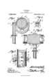
- FIG. 1 is a view partly in section and partly in elevation of an oar lock constructed in accordance with the present invention, the oar being shown in section within the oarlock.
- Fig. 2 is a section on line AB Fig. 1.
- Fig. 3 is a section on line C-D Fig. 1, the oar being shown in elevation.
- Fig. at is a view partly in section and partly in elevation showing a modified construction.
- FIG. 1 designates a shank having an annular shoulder 2 adapted to limit the downward movement of the shank in the socket provided therefor and extending from the upper portion of the shank is a yoke 3 having a trunnion 4:. extending inwardly from the free end thereof and directly opposite a locking pin 5 which is slidably mounted in the upper end port-ion of the shank 1 and is connected to a spring strip 6 attached to the shank. This strip serves to hold the pin 5 normally projected beyond the shank 1 and toward the trunnion 4c,
- Said pin thus serving as a movable bearing for a ring 7.
- Said ring has recesses 8 therein at diametrically opposed points, one of the recesses being adapted to receive the trunnion 4: while the pin 5 is adapted to pro ject into the other recess.
- the oar which has been indicated at 9, has plates 10 secured to opposite portions thereof, each plate being provided with outstanding ears 11 arranged in pairs and spaced apart a distance slightly greater than the width of the ring 7. These plates are adapted to be secured to the oar in any suitable manner and are preferably bowed transversely so as to fit snugly upon said oar. In assembling the parts the plates 10 are first placed within the ring 7 and with said ring seated between the ears 11.
- the oar 9 is then inserted between the plates 10 and said plates are fastened to it. It will be apparent therefore that the oar can be rotated within the ring but the ears 11 will prevent it from becoming displaced longitudinally relative thereto.
- said ring may be placed in position within the yoke 3 by placing the trunnion 4c in one of the notches 8 and then pressing the surface of the ring against the movable pin 5 until said pin is brought to a position in register with the opposed recess 8 whereupon the pin will move into the recess and thus lock the ring in position.
- the oar can, obviously, be operated in the usual manner and, by reason of the fact that the oar can be rotated within the ring 7, it will be apparent that there will be no difliculty in feathering the oar. Should the oar be released, the ears 11, by engaging the ring 7, will prevent it from slipping out of the boat.
- a screw 12 may be mounted within the shank 1, there being a thumb lever 13 or the like at one end of the screw while the other end of said screw is reduced in diameter and adapted to proj ect into a socket in the ring 7.
- a thumb lever 13 or the like at one end of the screw while the other end of said screw is reduced in diameter and adapted to proj ect into a socket in the ring 7.
- An oarlock including a yoke, a trunnion fixed relative thereto, a movable trunnion alining with the fixed trunnion, the two trunnions being oppositely disposed within the yoke, a spring for holding the movable trunnion normally projected into the yoke, a one-pieced continuous ring having diametrically opposed recesses for the reception
- Copies of this patent may be obtained for five cents each, by addressing the Commissioner of the trunnions, oppositely disposed plates for attachment to an oar, and spaced projections upon each plate for slidably engaging the ring, said plates being disposed within said ring and constituting means for holding an oar against longitudinal movement within the ring.
Landscapes
- Chemical & Material Sciences (AREA)
- Engineering & Computer Science (AREA)
- Combustion & Propulsion (AREA)
- Mechanical Engineering (AREA)
- Ocean & Marine Engineering (AREA)
- Adornments (AREA)
- Component Parts Of Construction Machinery (AREA)
- Orthopedics, Nursing, And Contraception (AREA)
Description
J. CAMPBELL.
OAR LOOK.
, 910. 1,026,654. Patented May 21, 1912.
UNITED STATES PATENT OFFICE.
JOHN CAMPBELL, OF MINNEAPOLIS, MINNESOTA, ASSIGNOR 0F FIFTY-ONE ONE- HUNDREDTI-IS T0 THOMAS E. MCDERMOTT, OF MINNEAPOLIS, MINNESOTA.
OAR-LOCK.
Specification of Letters Patent.
Application filed. May 12, 1910. Serial No. 560,939.
To all whom it may concern:
Be it known that I, JOHN CAMPBELL, a
citizen of the United States, residing at Minneapolis, in the county of Hennepin and State of Minnesota, have invented a new and useful Oar-Lock, of which the following is a specification.
This invention relates to oarlooks and its object is to provide a simple and compact device of thischaracter which is cheap to manufacture and to which an oar can be readily attached.
Another object is to provide an oarlock which does not interfere with any of the necessary movements of an oar and permits the oar to be readily feathered.
A further object is to provide an oarlock which securely holds the oar under all conditions, thus preventing its loss when released.
With these and other objects in view the invention consists of certain novel details of construction and combinations of parts hereinafter more fully described and pointed out in the claim.
In the accompanying drawings the preferred form of the invention has been shown.
In said drawings :-Figure 1 is a view partly in section and partly in elevation of an oar lock constructed in accordance with the present invention, the oar being shown in section within the oarlock. Fig. 2 is a section on line AB Fig. 1. Fig. 3 is a section on line C-D Fig. 1, the oar being shown in elevation. Fig. at is a view partly in section and partly in elevation showing a modified construction.
Referring to the figures by characters of reference 1 designates a shank having an annular shoulder 2 adapted to limit the downward movement of the shank in the socket provided therefor and extending from the upper portion of the shank is a yoke 3 having a trunnion 4:. extending inwardly from the free end thereof and directly opposite a locking pin 5 which is slidably mounted in the upper end port-ion of the shank 1 and is connected to a spring strip 6 attached to the shank. This strip serves to hold the pin 5 normally projected beyond the shank 1 and toward the trunnion 4c,
the said pin thus serving as a movable bearing for a ring 7. Said ring has recesses 8 therein at diametrically opposed points, one of the recesses being adapted to receive the trunnion 4: while the pin 5 is adapted to pro ject into the other recess. The oar, which has been indicated at 9, has plates 10 secured to opposite portions thereof, each plate being provided with outstanding ears 11 arranged in pairs and spaced apart a distance slightly greater than the width of the ring 7. These plates are adapted to be secured to the oar in any suitable manner and are preferably bowed transversely so as to fit snugly upon said oar. In assembling the parts the plates 10 are first placed within the ring 7 and with said ring seated between the ears 11. The oar 9 is then inserted between the plates 10 and said plates are fastened to it. It will be apparent therefore that the oar can be rotated within the ring but the ears 11 will prevent it from becoming displaced longitudinally relative thereto. After the oar has thus been mounted within the ring, said ring may be placed in position within the yoke 3 by placing the trunnion 4c in one of the notches 8 and then pressing the surface of the ring against the movable pin 5 until said pin is brought to a position in register with the opposed recess 8 whereupon the pin will move into the recess and thus lock the ring in position. After the shank 1 has been placed in its socket, the oar can, obviously, be operated in the usual manner and, by reason of the fact that the oar can be rotated within the ring 7, it will be apparent that there will be no difliculty in feathering the oar. Should the oar be released, the ears 11, by engaging the ring 7, will prevent it from slipping out of the boat. When it is desired to ship the oar by detaching it from the oarlock, it is merely necessary to pull outwardly on the spring 6 so as to withdraw the pin 5 from the adjoining recess 8. The said ring can then be slipped off of the trunnion 4 and thus re- A moved from the yoke.
Instead of utilizing a pin 5 and spring 6 such as shown in Fig. 1, a screw 12 may be mounted within the shank 1, there being a thumb lever 13 or the like at one end of the screw while the other end of said screw is reduced in diameter and adapted to proj ect into a socket in the ring 7. By turning the screw in one direction it can be disengaged from the ring and by turning it into the opposite direction it can be forced into the socket so as to secure the ring in place.
It is of course to be understood that various changes may be made in the construction and arrangement of the parts without departing from the spirit or sacrificing any of the advantages of the invention as de fined in the appended claim. A
What is claimed is An oarlock including a yoke, a trunnion fixed relative thereto, a movable trunnion alining with the fixed trunnion, the two trunnions being oppositely disposed within the yoke, a spring for holding the movable trunnion normally projected into the yoke, a one-pieced continuous ring having diametrically opposed recesses for the reception Copies of this patent may be obtained for five cents each, by addressing the Commissioner of the trunnions, oppositely disposed plates for attachment to an oar, and spaced projections upon each plate for slidably engaging the ring, said plates being disposed within said ring and constituting means for holding an oar against longitudinal movement within the ring.
In testimony that I claim the foregoing as my own, I have hereto affixed my signature in the presence of two Witnesses.
JOHN CAMPBELL.
WVitnesses:
SAMUEL BERMAN, CHAS. E. GoLDBLUM.
of Patents,
Washington, D. G.
Priority Applications (1)
| Application Number | Priority Date | Filing Date | Title |
|---|---|---|---|
| US56093910A US1026654A (en) | 1910-05-12 | 1910-05-12 | Oar-lock. |
Applications Claiming Priority (1)
| Application Number | Priority Date | Filing Date | Title |
|---|---|---|---|
| US56093910A US1026654A (en) | 1910-05-12 | 1910-05-12 | Oar-lock. |
Publications (1)
| Publication Number | Publication Date |
|---|---|
| US1026654A true US1026654A (en) | 1912-05-21 |
Family
ID=3094948
Family Applications (1)
| Application Number | Title | Priority Date | Filing Date |
|---|---|---|---|
| US56093910A Expired - Lifetime US1026654A (en) | 1910-05-12 | 1910-05-12 | Oar-lock. |
Country Status (1)
| Country | Link |
|---|---|
| US (1) | US1026654A (en) |
Cited By (1)
| Publication number | Priority date | Publication date | Assignee | Title |
|---|---|---|---|---|
| US2461092A (en) * | 1945-11-17 | 1949-02-08 | George H Sterling | Oar protector |
-
1910
- 1910-05-12 US US56093910A patent/US1026654A/en not_active Expired - Lifetime
Cited By (1)
| Publication number | Priority date | Publication date | Assignee | Title |
|---|---|---|---|---|
| US2461092A (en) * | 1945-11-17 | 1949-02-08 | George H Sterling | Oar protector |
Similar Documents
| Publication | Publication Date | Title |
|---|---|---|
| US998562A (en) | Oar-lock. | |
| US624628A (en) | Bolt-head | |
| US1016237A (en) | Nut-lock. | |
| US1185178A (en) | Oar-lock-supporting device. | |
| US571212A (en) | Hose-coupling | |
| US998852A (en) | Locking device. | |
| US711068A (en) | Attachment for vises. | |
| US1041985A (en) | Reversing mechanism. | |
| US601519A (en) | Permutation-lock | |
| US732336A (en) | Rowing apparatus. | |
| US688012A (en) | Lifting-jack. | |
| US612488A (en) | Oar-lock | |
| US383244A (en) | Oar and oar-lock | |
| US1293543A (en) | Safety snap-hook. | |
| US469277A (en) | Alfred siebert | |
| US770641A (en) | Clutch | |
| US1275737A (en) | Oar-lock. | |
| US50264A (en) | Improved rowlock | |
| US893281A (en) | Universal joint. | |
| US787084A (en) | Apparatus for the propulsion of ships. | |
| US685282A (en) | Cylinder-wrench. | |
| US338345A (en) | Rowlock | |
| US813896A (en) | Oar-lock. | |
| US579719A (en) | Hoisting apparatus | |
| US1006561A (en) | Rowing apparatus. |