TECHNICAL FIELD
The present invention relates to a method of manufacturing a fan blade made of a fiber-reinforced composite material, which is a blank sheet comprising a plurality of fibers arranged in parallel with each other consolidated by a resin, and an apparatus for manufacturing the fan blade.
BACKGROUND ART
A turbofan engine used as an engine of an aircraft comprises a fan that produces most of the thrust and a core engine (turbojet engine) provided with a turbine that is disposed behind the fan and drive the fan. The fan and the core engine are coaxially arranged, air sucked by the fan from the front of the engine is divided into air (Gf) that passes through the fan and is discharged to the rear and air (Gc) that is introduced into the core engine, used for combustion to make the turbine rotate and then discharged to the rear. The ratio between the two flows of air (Gf/Gc) is referred to as a bypass ratio.
The higher the bypass ratio, the higher the fuel efficiency is, so that turbofan engines of high bypass ratios have been developed in recent years. As the bypass ratio increases, the ratio of the diameter of the fan to the diameter of the core engine increases, so that the length of the fan blades forming the fan increases. Although conventional fan blades are made of titanium, an aluminum alloy or the like, it has been proposed to use a fiber-reinforced composite material for the fan blades in order to reduce weight and ensure strength in the trend toward larger fan blades (see Patent Documents 1 and 2).
Such a fan blade made of a composite material is molded by thermoforming from a blank sheet that comprises a plurality of fibers arranged in parallel with each other (filaments) consolidated by a resin (a polymer). To mold a product having a three-dimensional shape, such as the fan blade, thermoforming from a blank sheet having a flat shape, the blank sheet is heated to make the resin soften, and then (a) the blank sheet is sandwiched between two molds, (b) the blank sheet is pressed against a mold by compressed air, or (c) the space between a mold and the blank sheet is decompressed to make the blank sheet cling to the mold (see Patent Documents 3 and 4).
PRIOR ART DOCUMENT
Patent Document
Patent Document 1: Japanese Patent Laid-Open No. 2007-112132
Patent Document 2: Japanese Patent Laid-Open No. 2011-69286
Patent Document 3: Japanese Patent Laid-Open No. 561-179720
Patent Document 4: Japanese Patent Laid-Open No. H06-239340
SUMMARY OF THE INVENTION
Problems to be Solved by the Invention
In general, the fan blade has a twisted shape in consideration of the aerodynamic characteristics, and therefore, the surface of the mold that transfers the shape also has a twisted shape. In the case (a) described above, if the mold has such a twisted surface, as the blank sheet is shaped between the two molds to conform to the shape of the molds, wrinkling or entanglement can occur in a peripheral part of the shaped part or other parts. Furthermore, when the two molds are brought closer to sandwich the blank sheet, the blank sheet can move along the uneven shape of the mold and be misaligned with respect to the center of the mold, and the blank sheet can be unable to be properly molded.
In the case (b), if the blank sheet pressed against the mold by the compressed air is substantially deformed, wrinkling is likely to occur as in the case (a), and compressed air of high pressure is needed to properly press the blank sheet against the mold. In the case (c), if the blank sheet clinging to the mold due to decompression is substantially deformed, wrinkling is likely to occur as in the case (a). In addition, although substantial decompression is needed to properly make the blank sheet cling to the mold, there is a limit to the decompression.
In addition, in the cases (b) and (c), since the blank sheet is not sandwiched between two molds but is pressed against one mold by compressed air or made to cling to one mold by decompression, a blank sheet that is hard to deform because of the thickness or material can hardly be molded.
In view of the circumstances described above, an object of the present invention is to provide a method of manufacturing a fan blade by thermoforming from a blank sheet that comprises a plurality of fibers arranged in parallel with each other consolidated by a resin while preventing occurrence of wrinkling, and an apparatus for manufacturing the fan blade.
Means for Solving the Problems
To attain the object described above, an aspect of the invention is directed to a method of manufacturing a fan blade, comprising heating a blank sheet including a plurality of main fibers arranged in parallel with each other, a plurality of auxiliary fibers arranged in parallel with each other so as to intersect with the main fibers, and a resin that consolidates the main fibers and the auxiliary fibers, and pressing the heated blank sheet against a fan blade mold, wherein the fan blade mold is shaped so that a length thereof in a longitudinal direction along a surface of a center part thereof in a width direction is shorter than a length thereof in the longitudinal direction along a surface of end parts thereof in the width direction, and when the blank sheet is pressed against the fan blade mold, the blank sheet is pressed against the fan blade mold with the direction of the main fibers aligned with the longitudinal direction of the fan blade mold, and the center part in the width direction of the blank sheet at an end part in the longitudinal direction of the fan blade mold is pulled with a greater force than the end parts in the width direction of the blank sheet at the end part in the longitudinal direction of the fan blade mold.
In addition, an aspect of the invention is directed to an apparatus for manufacturing a fan blade, the apparatus being configured to heat a blank sheet including a plurality of main fibers arranged in parallel with each other, a plurality of auxiliary fibers arranged in parallel with each other so as to intersect with the main fibers, and a resin that consolidates the main fibers and the auxiliary fibers, and press the heated blank sheet against a fan blade mold, and the apparatus comprising pressing unit that presses the blank sheet against the fan blade mold with the direction of the main fibers aligned with the longitudinal direction of the fan blade mold, wherein the fan blade mold is shaped so that a length thereof in a longitudinal direction along a surface of a center part thereof in a width direction is shorter than a length thereof in the longitudinal direction along a surface of end parts thereof in the width direction, the fan blade mold has a margin part having a shape different from the shape of the fan blade formed along a perimeter thereof, and a cross section angle of the margin part with respect to the direction of pressing the blank sheet is more acute at the center part in the width direction of the end part in the longitudinal direction than at the end parts in the width direction of the end part in the longitudinal direction.
Advantageous Effects of the Invention
With the method of manufacturing a fan blade and the apparatus for manufacturing a fan blade according to the present invention, occurrence of wrinkling can be prevented when the fan blade is formed by thermoforming from a blank sheet comprising a plurality of fibers arranged in parallel with each other consolidated by a resin.
BRIEF DESCRIPTION OF THE DRAWINGS
FIG. 1 is a schematic side cross-sectional view of a turbofan engine provided with a fan blade.
FIG. 2 is an illustrative diagram showing a fan blade mold and a blank sheet comprising main fibers arranged in the longitudinal direction of the fan blade and auxiliary fibers arranged to intersect with the main fibers used in a method of manufacturing a fan blade according to an embodiment of the present invention.
FIG. 3 is a schematic cross-sectional view of a thermoforming apparatus for manufacturing the fan blade.
FIG. 4A is a plan view of the fan blade mold and a lower blank holder.
FIG. 4B is a side view of the fan blade mold and the lower blank holder.
FIG. 5 is a perspective view of the fan blade mold and the lower blank holder shown in FIG. 4 and the blank sheet primarily bent.
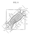
FIG. 6 is an illustrative diagram showing the blank sheet placed on the fan blade mold and the lower blank holder shown in FIGS. 4 and 5, in which the magnitude of the force of pulling the blank sheet is shown by the length of the arrows.
FIG. 7A is a partial cross-sectional view of a center part in the width direction (a part pulled with a greater force) of an end part in the longitudinal direction of the fan blade mold shown in FIG. 6.
FIG. 7B is a partial cross-sectional view of an end part in the width direction (a part pulled with a smaller force) of the end part in the longitudinal direction of the fan blade mold shown in FIG. 6.
FIG. 8 is a plan view of a fan blade mold and a lower blank holder forming an apparatus for manufacturing a fan blade according to a modification of the present invention and a blank sheet placed on the fan blade mold and the lower blank holder.
FIG. 9 is a side cross-sectional view of essential parts of the lower blank holder shown in FIG. 8.
MODE FOR CARRYING OUT THE INVENTION
In the following, a preferred embodiment of the present invention will be described in detail. The specific dimensions, materials, numerical values and the like shown in the embodiment are given for the illustrative purpose to facilitate understanding of the present invention and are not intended to limit the present invention unless otherwise specified. In the specification and the drawings, elements having substantially the same function or configuration are denoted by the same reference numeral, and redundant description thereof will be omitted. Illustration of elements that are not relevant to the present invention will be omitted.
(Turbofan Engine 1)
FIG. 1 is a schematic side cross-sectional view of a turbofan engine 1 provided with a fan blade. The turbofan engine 1 comprises a fan 2 that produces most of the thrust and a core engine 3 that is disposed behind the fan 2 and is provided with a turbine that drives the fan 2.
The core engine 3 is a turbojet engine that comprises a low pressure compressor 31, a high pressure compressor 32, a combustion chamber 33, a high pressure turbine 34, a low pressure turbine 35 and a fan turbine 36, viewed from upstream to downstream. The high pressure turbine 34 is coupled to the high pressure compressor 32 by a high pressure shaft 37, the low pressure turbine 35 is coupled to the low pressure compressor 31 by a low pressure shaft 38, and the fan turbine 36 is coupled to the fan 2 by a fan shaft 39. Any one of the combination of the high pressure turbine 34 and the high pressure compressor 32 and the combination of the low pressure turbine 35 and the low pressure compressor 31 may be omitted.
(Fan Blade 21)
The fan 2 is provided with a plurality of fan blades 21 arranged at intervals in the circumferential direction, and a fan case 4 having substantially a cylindrical shape is disposed around the fan 2 to surround the fan 2. The fan case 4 is attached to a casing 30 of the core engine 3 by a plurality of struts (support rods) 5 arranged at intervals in the circumferential direction. The fan 2 housed in the fan case 4 comprises a fan disk 22 attached to the fan shaft 39 and the plurality of fan blades 21 provided on the fan disk 22 at intervals in the circumferential direction. The fan blades 21 have a substantially twisted shape in consideration of the aerodynamic characteristics. In the following, a method of manufacturing the fan blade 21 and an apparatus for manufacturing the fan blade 21 will be described.
(Blank Sheet 7)
FIG. 2 shows a fan blade mold 6 b (referred to also as a drag 6 b, hereinafter) and a blank sheet 7 pressed against the fan blade mold 6 b. The blank sheet 7 comprises a plurality of main fiber 71 arranged in parallel with each other, a plurality of auxiliary fibers 72 arranged in parallel with each other to intersect with the main fibers 71, and a resin that consolidates the main fibers 71 and the auxiliary fibers 72. A fan blade 21 made of fiber reinforced plastics (FRP), such as carbon fiber reinforced plastics (CFRP), is manufactured by stacking a plurality (8 to 16, for example) of such blank sheets 7 that comprise the resin reinforced by the fibers 71 and 72 and bonding the blank sheets 7 to each other as described below. As required, an interleaf made of a thermoplastic resin may be provided between the blank sheets 7 stacked on one another to improve the adhesion between the layers.
A reinforcing fiber, such as a carbon fiber, an aramid fiber or a glass fiber, is used as the main fibers 71 and the auxiliary fibers 72. The main fibers 71 are oriented in parallel with the longitudinal direction of the fan blade 21 (the longitudinal direction Y of the drag 6 b), which is the direction in which the main fibers 71 are pulled by the centrifugal force during rotation of the fan 2, and the auxiliary fibers 72 comprise first auxiliary fibers 72 a oriented at an angle of 45 degrees with respect to the main fibers 71 and second auxiliary fibers 72 b oriented at an angle of −45 degrees with respect to the main fibers 71. The angles of orientation of the first auxiliary fibers 72 a and the second auxiliary fibers 72 b are not limited to these angles, and the direction of the main fibers 71 may not be in parallel with the longitudinal direction Y of the drag 6 b and may be slightly inclined with respect to the longitudinal direction Y (within a range of ±30 degrees with respect to the longitudinal direction Y, for example).
A thermoplastic resin, such as a polyethylene resin, a polypropylene resin, a polystyrene resin, an ABS resin, a polyvinyl chloride resin, a methyl methacrylate resin, a nylon resin, a fluorocarbon resin, a polycarbonate resin or a polyester resin, is used as the resin that consolidates the main fibers 71 and the auxiliary fibers 72. The thermoplastic resin has a property that the resin softens to exhibit plasticity when the resin is heated and hardens when the resin is cooled.
The blank sheet 7 is molded into a three-dimensional shape by pressing the blank sheet 7 heated to make the resin soften against the drag 6 b with the direction of the main fibers 71 aligned with the longitudinal direction of the fan blade mold (drag) 6 b with the shape of a lower surface of a molding transferred thereto (thermoforming). A required part is cut out of the molding, and a plurality of such cut parts are stacked and bonded to each other to form the fan blade 21. The blank sheets 7 to be bonded to each other may be molded with molds of different shapes into different three-dimensional shapes.
(Thermoforming Apparatus TF)
FIG. 3 is a schematic cross-sectional view of a thermoforming apparatus TF for manufacturing the fan blade 21. The blank sheet 7 is molded into a three-dimensional shape by the thermoforming apparatus TF. The thermoforming apparatus TF comprises the fan blade mold (drag) 6 b, a paired fan blade mold 6 a (referred to also as a cope 6 a, hereinafter) with the shape of an upper surface of a molding transferred, a blank holder device 8 that holds the blank sheet 7, and a heater 9 that heats the blank sheet 7. The cope 6 a and the drag 6 b form one fan blade mold unit 6.
As shown in FIG. 3, the blank holder device 8 comprises an upper blank holder 8 a and a lower blank holder 8 b that sandwich the blank sheet 7. The upper blank holder 8 a and the lower blank holder 8 b have a frame-like shape, and the blank sheet 7 is held between the upper blank holder 8 a and the lower blank holder 8 b at a part except for a center part thereof, at which the blank sheet 7 faces shape transferring parts (effective molding parts) of the cope 6 a and the drag 6 b. The blank sheet 7 is placed on the lower blank holder 8 b.
The blank sheet 7 placed on the lower blank holder 8 b is heated by the heater 9, which is disposed between the upper blank holder 8 a and the lower blank holder 8 b, to a temperature at which the resin softens (a plastic temperature). The heater 9 is removed from between the upper blank holder 8 a and the lower blank holder 8 b once the heating is completed, in order that the blank sheet 7 is held by the blank holder device 8 and sandwiched between the cope 6 a and the drag 6 b. An infrared ray heater (an IR heater) is used as the heater 9, for example.
The drag 6 b incorporates a heating pipe 61 b that heats the drag 6 b and a cooling pipe 62 b that cools the drag 6 b. A heating fluid flows in the heating pipe 61 b to prevent the blank sheet 7 heated to the plastic temperature by the heater 9 from being cooled to a temperature lower than the plastic temperature when the blank sheet 7 comes into contact with the drag 6 b. A cooling fluid flows in the cooling pipe 62 b in order that, after the blank sheet 7 is molded between the cope 6 a and the drag 6 b, the drag 6 b is cooled to a temperature lower than the plastic temperature to make the molded blank sheet 7 harden. The cope 6 a also incorporates a similar heating pipe 61 a and a similar cooling pipe 62 a. As an alternative to the heating pipes 61 a and 61 b, a heating device, such as a heating wire or a high-frequency heating device, may be used.
The upper blank holder 8 a is attached to the cope 6 a and is raised and lowered integrally with the cope 6 a by a hydraulic device or the like. The hydraulic device forms pressing unit that presses the blank sheet 7 sandwiched between the upper blank holder 8 a and the lower blank holder 8 b against the drag 6 b. Alternatively, the cope 6 a and the upper blank holder 8 a may be independently raised and lowered by separate hydraulic devices.
A guide rod 81 provided on a lower part of the lower blank holder 8 b is inserted in a guide hole 63 formed in the drag 6 b, thereby preventing the lower blank holder 8 b from becoming horizontally misaligned with the drag 6 b when the lower blank holder 8 b is raised and lowered. The guide rod 81 is connected to a hydraulic device that provides a predetermined resistance force to hinder pressing down of the guide rod 81. When the lower blank holder 8 b is pressed down by the lowering upper blank holder 8 a, the resistance force described above allows the blank sheet 7 to be sandwiched between the upper blank holder 8 a and the lower blank holder 8 b with a predetermined force.
As described above, the center part of the blank sheet 7 heated to a temperature equal to or higher than the plastic temperature held between the frame-like shaped upper blank holder 8 a and lower blank holder 8 b is pressed against the drag 6 b from above. The drag 6 b, the lower blank holder 8 b and a margin part 65 of the drag 6 b will be described in detail with reference to FIGS. 4 to 7.
(Fan Blade Mold 6 b)
FIG. 4A is a plan view of the fan blade mold (drag) 6 b and the lower blank holder 8 b, FIG. 4B is a side view of the same, and FIG. 5 is a perspective view showing the drag 6 b and the lower blank holder 8 b shown in FIGS. 4A and 4B and the blank sheet 7 primarily bent. FIG. 6 is an illustrative diagram showing the blank sheet 7 placed on the drag 6 b and the lower blank holder 8 b shown in FIGS. 4A, 4B and 5, in which the length of the arrows shows the magnitude of the force of pulling the blank sheet 7. FIGS. 7A and 7B are partial cross-sectional views of the drag 6 b and the lower blank holder 8 b shown in FIG. 6. FIG. 7A is a partial cross-sectional view of a center part in the width direction of an end part in the longitudinal direction of the drag 6 b (a part pulled with a greater force), FIG. 7B is a partial cross-sectional view of an end part in the width direction of the end part in the longitudinal direction of the drag 6 b (a part pulled with a smaller force). The drag 6 b has a fan blade part 64 (dotted part) with the shape of one of the plurality of stacked blank sheets 7 forming the fan blade 21 transferred thereto, and a margin part 65 that is formed along the perimeter of the fan blade part 64 and does not have the shape of the fan blade 21. Such a drag 6 b is slidably inserted into a lower through-hole 82 that is formed in the lower blank holder 8 b so as to vertically penetrate the lower blank holder 8 b.
As shown in FIG. 4B, the lower through-hole 82 of the lower blank holder 8 b is slightly larger than the drag 6 b, there is a gap Gb between the inner surface of the lower through-hole 82 and the side surface of the drag 6 b, and the gap Gb allows the drag 6 b to be slidably inserted into the lower through-hole 82. As shown in FIG. 7A, the upper blank holder 8 a also has a lower through-hole 85 into which the drag 6 b is to be inserted, there is a gap Ga between the inner surface of the lower through-hole 85 and the side surface of the drag 6 b, and the gap Ga allows the upper blank holder 8 a to be lowered to a level lower than the top surface of the drag 6 b with the blank sheet 7 interposed therebetween. The dimension of the gap Ga is set to be equal to or greater than the thickness of the blank sheet 7.
Since the fan blade 21 is substantially twisted in order to improve the aerodynamic characteristics as described above, the fan blade mold (drag) 6 b and the paired fan blade mold (cope) 6 a with the shape of the fan blade 21 transferred thereto also have a twisted surface shape. More specifically, as shown in FIGS. 4A, 4B and 5, the drag 6 b is shaped (into a substantially col-like shape) to have peak parts (top parts) 66 spaced apart from each other in the longitudinal direction and a ridge part 67 that connects the peak parts 66. In addition, as shown in FIG. 6, the drag 6 b is shaped so that the length in the longitudinal direction of a center part 64 x in the width direction of the fan blade part 64 along the surface of the drag 6 b (which is not the linear length but the length along the surface of the drag 6 b) is shorter than the length in the longitudinal direction of end parts 64 y in the width direction along the surface of the drag 6 b (which is not the linear length but the length along the surface of the drag 6 b). The cope 6 a is shaped to have projections and recesses that are substantially counterparts of those of the drag 6 b.
(Margin Part 65)
As shown in FIGS. 6, 7A and 7B, the margin part 65 of the drag 6 b is not uniformly formed along the perimeter of the fan blade part 64 but has different cross-sectional shapes between a center part 65 x in the width direction of an end part in the longitudinal direction of the drag 6 b and end parts 65 y in the width direction of the end part in the longitudinal direction of the drag 6 b. The “width direction” is a direction perpendicular to the longitudinal direction Y (see FIG. 4A) of the drag 6 b, and the “cross-sectional shape” is the shape of a cross section of the margin part 65 cut in the direction of pressing the blank sheet 7 (vertical direction).
More specifically, the margin part 65 is shaped so that the angle (see FIG. 7A) of the cross-sectional shape of the center part 65 x in the width direction of the end part in the longitudinal direction of the drag 6 b is more acute than the angle (see FIG. 7B) of the cross-sectional shape of the end parts 65 y in the width direction of the end part in the longitudinal direction of the drag 6 b. More specifically, the angle of the cross-sectional shape of the center part 65 x in the width direction of the margin part 65 (referred to as a cross section angle, hereinafter) is substantially a right angle, while the cross-sectional shape of the end parts 65 y in the width direction of the margin part 65 is the shape of a gentle slope. The angle of the cross-sectional shape of the center part 65 x in the width direction of the drag 6 b (see FIG. 7A) and the angle of the cross-sectional shape of the end parts 65 y in the width direction (see FIG. 7B) can be set at any angle, depending on the shape of the blade.
(Method of Manufacturing Fan Blade 21)
First, the lower blank holder 8 b shown in FIGS. 4A, 4B and 5 is moved upward until the top surface of the lower blank holder 8 b is positioned at a level higher than the drag 6 b (see FIG. 3). The blank sheet 7 heated to a temperature equal to or higher than the plastic temperature by the heater 9 or the like is placed on the top surface of the lower blank holder 8 b as shown in FIG. 6. Since the fan blade 21 is substantially twisted in order to improve the aerodynamic characteristics as described above, the drag 6 b with the shape transferred thereto also has a twisted surface shape. More specifically, as shown in FIG. 5, the drag 6 b is shaped (into a substantially col-like shape) to have the peak parts 66 spaced apart from each other in the longitudinal direction and the ridge part 67 that connects the peak parts 66. Therefore, if the blank sheet 7 of a flat shape is pressed against the drag 6 b in a thermoforming molding step, the blank sheet 7 first comes into point contact with the peak parts 66 of the drag 6 b, and an appropriate tension is not applied to the center part of the blank sheet 7 that is opposed to the ridge part 67 between the peak parts 66, which causes wrinkling.
To avoid this problem, as shown in FIG. 5, the blank sheet 7 is deformed into a curved shape in advance (primary bending) in order that, when the blank sheet 7 is pressed against the drag 6 b, the blank sheet 7 first comes into line contact with the ridge part 67 of the fan blade part 64 of the drag 6 b. Since the blank sheet 7 first comes into line contact with the ridge part 67 of the fan blade part 64 of the drag 6 b, an appropriate tension can be maintained over the entire blank sheet 7 throughout the thermoforming molding step in which the blank sheet 7 is pressed against the drag 6 b, and occurrence of wrinkling can be prevented. The shape of the blank sheet 7 bent in advance (primarily bent) is preferably the shape of a developable surface (a surface that can be developed into a flat surface without expansion or shrinkage), because occurrence of wrinkling can be prevented when the blank sheet 7 of a flat shape is primarily bend. The top surface of the lower blank holder 8 b shown in FIG. 5 has a curved shape that conforms to the shape of the lower surface of the primarily bent blank sheet 7. In FIG. 4A, an intersection angle α between a generatrix direction X of the primarily bent blank sheet 7 and the longitudinal direction Y of the drag 6 b for the blank sheet 7 is equal to or greater than 10 degrees and equal to or smaller than 80 degrees and is preferably equal to or greater than 30 degrees and equal to or smaller than 60 degrees. If the intersection angle α is equal to or greater than 10 degrees and equal to or smaller than 80 degrees, the amount of deformation (deformation from a developable surface to a non-developable surface) in secondary bending in the thermoforming molding can be reduced. If the intersection angle α is equal to or greater than 30 degrees and equal to or smaller than 60 degrees, the amount of deformation can be further reduced, and occurrence of wrinkling can be prevented with higher reliability.
As shown in FIG. 2, the blank sheet 7 is placed on the top surface of the lower blank holder 8 b with the direction of the main fibers 71 aligned with the longitudinal direction Y of the drag (fan blade mold) 6 b. According to this embodiment, the blank sheet 7 is placed on the top surface of the lower blank holder 8 b with the main fibers 71 oriented in parallel with the longitudinal direction Y of the drag 6 b to increase the strength and rigidity of the fan blade 21, which is subject to a centrifugal force, as far as possible. However, the main fibers 71 may not be in parallel with the longitudinal direction Y of the drag 6 b, if adequate strength and rigidity of the fan blade 21 can be ensured. In that case, the angle between the direction of the main fibers 71 and the longitudinal direction Y of the drag 6 b is preferably equal to or smaller than 30 degrees and more preferably equal to or smaller than 10 degrees. This is because, as far as the angle falls within this range, adequate strength and rigidity of the fan blade 21 can be ensured. That is, to align the direction of the main fibers 71 with the longitudinal direction Y of the drag 6 b is not exclusively to orient the main fibers 71 in parallel with the longitudinal direction Y of the drag 6 b but may be to orient the main fibers 71 so as to form an angle within a range of −30 degrees to +30 degrees (more preferably within a range of −10 degrees to +10 degrees) with the longitudinal direction Y of the drag 6 b.
The upper blank holder 8 a and the cope 6 a shown in FIG. 3 are then integrally lowered by pressing unit, which is constituted by a hydraulic device or the like. The lower surface of the cope 6 a is shaped to conform to the shape of the top surface of the drag 6 b, and the lower surface of the upper blank holder 8 a is shaped to conform to the shape of the top surface of the lower blank holder 8 b. The peripheral part of the blank sheet 7 is sandwiched between the upper blank holder 8 a and the lower blank holder 8 b, the lower blank holder 8 b is lowered while being guided by the guide rod 81 as the upper blank holder 8 a and the cope 6 a are lowered, and the center part of the blank sheet 7 is pressed against the drag 6 b, collapsed by the cope 6 a and held between the cope 6 a and the drag 6 b.
In this way, with the direction of the main fibers 71 of the blank sheet 7 aligned with the longitudinal direction Y of the drag 6 b, the center part of the blank sheet 7 is pressed against the drag 6 b, and the peripheral part of the blank sheet 7 is sandwiched between the upper blank holder 8 a and the lower blank holder 8 b. As described above, to align the direction of the main fibers 71 of the blank sheet 7 with the longitudinal direction Y of the drag 6 b is not exclusively to orient the main fibers 71 in parallel with the longitudinal direction Y of the drag 6 b but may be to orient the main fibers 71 so as to form an angle within a range of −30 degrees to +30 degrees (more preferably within a range of −10 degrees to +10 degrees) with the longitudinal direction Y of the drag 6 b. Since the blank sheet 7 is held between the frame-like shaped blank holders 8 a and 8 b, the blank sheet 7 is prevented from being horizontally displaced with respect to the drag 6 b and is pressed against the drag 6 b with an appropriate tension applied in the direction of the main fibers 71.
Therefore, when the blank sheet 7 is pressed and molded between the cope 6 a and the drag 6 b, the center part of the blank sheet 7 is appropriately pressed and constantly pulled in the direction of the main fibers 71, so that wrinkling is unlikely to occur. Since the blank sheet 7 is sandwiched between the cope 6 a and the drag 6 b, a great force can be applied to the blank sheet 7, so that the blank sheet 7 can be precisely deformed to conform to the shapes of the cope 6 a and the drag 6 b when the blank sheet 7 is hard to deform because of the material, thickness or the like of the blank sheet 7. As required, at least a part of the part of the blank sheet 7 sandwiched between the upper blank holder 8 a and the lower blank holder 8 b may be configured to slide between the blank holders 8 a and 8 b when the blank sheet 7 is pressed against the drag 6 b, thereby preventing an excessive tension from being applied to the blank sheet 7.
Furthermore, the blank sheet 7 may be pulled at an end part 7 a in the longitudinal direction in the direction of the main fibers 71 when the blank sheet 7 is pressed against the drag 6 b, thereby preventing occurrence of wrinkling of the blank sheet 7. The drag 6 b with the shape of the fan blade 21 transferred thereto has a twisted shape as described above. More specifically, the drag 6 b is shaped so that the length in the longitudinal direction of the center part 64 x in the width direction of the fan blade part 64 along the surface of the drag 6 b (which is not the linear length but the length along the surface of the drag 6 b) is shorter than the length in the longitudinal direction of the end parts 64 y in the width direction along the surface of the drag 6 b (which is not the linear length but the length along the surface of the drag 6 b). Therefore, if the blank sheet 7 is pressed against the drag 6 b and all the main fibers 71 shown in FIG. 2 are pulled with a uniform force in the thermoforming molding step, main fibers 71 x (see FIG. 2) in the center part 64 x in the width direction have an excess length, and wrinkling tends to occur in the main fibers 71 x in the center part 64 x in the width direction.
To avoid this problem, as shown by the arrows A in FIG. 6, when the blank sheet 7 is pressed against the drag 6 b having the shape described above, a center part 7 x in the width direction of the blank sheet 7 that comes into contact with the center part 65 x in the width direction of the margin part 65 of the end part in the longitudinal direction of the drag 6 b is pulled with a greater force than end parts 7 y in the width direction of the blank sheet 7 that come into contact with the end parts 65 y in the width direction of the margin part 65 of the end part in the longitudinal direction of the drag 6 b, thereby preventing the main fibers 71 x in the center part 64 x in the width direction from having an excess length and thereby preventing wrinkling from occurring in the main fibers 71 x.
That is, as shown in FIGS. 6, 7A and 7B, the cross section angle of the center part 65 x in the width direction of the margin part 65 of the end part in the longitudinal direction of the drag 6 b is more acute than the cross section angle of the end parts 65 y in the width direction of the margin part 65 of the end part in the longitudinal direction of the drag 6 b. Therefore, when the blank sheet 7 held by the blank holder device 8 is lowered and pressed against the drag 6 b, as shown by the arrows A in FIGS. 6 and 7A, the center part 7 x in the width direction of the end part 7 a in the longitudinal direction of the blank sheet 7 is pulled along the main fibers 71 with a greater force than the end parts 7 y in the width direction of the end part 7 a in the longitudinal direction of the blank sheet 7. The length of the arrows A shown in FIGS. 6, 7A and 7B shows the magnitude of the force of pulling the blank sheet 7.
Since the center part 7 x in the width direction of the end part 7 a in the longitudinal direction of the blank sheet 7 is pulled along the main fibers 71 with a greater force than the end parts 7 y in the width direction of the end part 7 a in the longitudinal direction of the blank sheet 7 as described above, the main fibers 71 x (see FIG. 2) in the center part of the blank sheet 7 can be prevented from having an excess length, and wrinkling can be prevented from occurring in the center part of the molding. The force of pulling each main fiber 71 can be adjusted by changing the cross section angle of the center part 65 x and the end parts 65 y in the width direction of the margin part 65 along the width direction.
(Modifications)
A modification according to the present invention is shown in FIGS. 8 and 9. FIG. 8 is a plan view of the primarily bent blank sheet 7 placed on the drag 6 b and the lower blank holder 8 b according to the modification, and FIG. 9 is a side cross-sectional view of essential parts of the components shown in FIG. 8. As shown in FIG. 8, a projection 83 having a bead-like shape and extending in a direction intersecting with the longitudinal direction of the drag 6 b is formed on the top surface of the lower blank holder 8 b (the surface facing the upper blank holder 8 a) at a position outside the end part in the longitudinal direction of the drag 6 b. A recess 84 (see FIG. 9) shaped to conform to the shape of the projection 83 is formed in the lower surface of the upper blank holder 8 a. The projection 83 and the recess 84 are formed to extend in a direction substantially perpendicular to the longitudinal direction of the drag 6 b. As required, the upper blank holder 8 a may have the projection 83, and the lower blank holder 8 b may have the recess 84.
With this configuration, when the heated blank sheet 7 in the plastic state is sandwiched between the upper blank holder 8 a and the lower blank holder 8 b, the part of the blank sheet 7 pushed by the projection 83 gets into the recess 84, so that the blank sheet 7 is pulled in the direction of the main fibers 71, and the part of the blank sheet 7 held by the projection 83 and the recess 84 is prevented from sliding in the direction of the main fibers 71. Therefore, when the blank sheet 7 in the plastic state sandwiched between the upper blank holder 8 a and the lower blank holder 8 b is pressed against the drag 6 b, a higher tension can be applied to the end parts 7 a of the blank sheet 7 in the longitudinal direction of the drag 6 b than end parts 7 b of the blank sheet 7 in the direction perpendicular to the longitudinal direction of the drag 6 b, so that occurrence of wrinkling in the molding can be prevented. A frictional part, such as one comprising a plurality of fine projections and recesses, may be formed on the projection 83 and the recess 84 to prevent sliding of the part of the blank sheet 7 sandwiched between the projection 83 and the recess 84 with higher reliability.
Alternatively, the projection 83 described above may be formed on the upper surface of the lower blank holder 8 b at a desired position along the circumference of the drag 6 b, and the recess 84 may be formed in the lower surface of the upper blank holder 8 a at a corresponding position, thereby preventing sliding of the part of the blank sheet at which the projection 83 and the recess 84 are formed and increasing the tension at the desired position. A part of the blank sheet 7 at which the projection 83 and the recess 84 are not formed may be allowed to slide between the blank holders 8 a and 8 b to a greater extent than the part of the blank sheet 7 at which the projection 83 and the recess 84 are formed.
Although a preferred embodiment of the present invention has been described with reference to the accompanying drawings, of course, the present invention is not limited to the embodiment described above, and various alterations and modifications described in the claims are included in the technical scope of the present invention. For example, in FIG. 3, after the blank sheet 7 is held by the blank holder device 8 (the upper blank holder 8 a and the lower blank holder 8 b), a heating device other than the heater 9 may be used to heat the blank sheet 7 to a temperature at which the resin softens. In that case, the upper blank holder 8 a is preferably separate from the cope 6 a.
Summary of Embodiment
According to a first aspect of the present invention, there is provided a method of manufacturing a fan blade, comprising heating a blank sheet including a plurality of main fibers arranged in parallel with each other, a plurality of auxiliary fibers arranged in parallel with each other so as to intersect with the main fibers, and a resin that consolidates the main fibers and the auxiliary fibers, and pressing the heated blank sheet against a fan blade mold, wherein the fan blade mold is shaped so that a length thereof in a longitudinal direction along a surface of a center part thereof in a width direction is shorter than a length thereof in the longitudinal direction along a surface of end parts thereof in the width direction, and when the blank sheet is pressed against the fan blade mold, the blank sheet is pressed against the fan blade mold with the direction of the main fibers aligned with the longitudinal direction of the fan blade mold, and the center part in the width direction of the blank sheet at an end part in the longitudinal direction of the fan blade mold is pulled with a greater force than the end parts in the width direction of the blank sheet at the end part in the longitudinal direction of the fan blade mold.
According to a second aspect of the present invention, in the first aspect described above, the fan blade mold is shaped to have peak parts spaced apart from each other and a ridge part that connects the peak parts, the blank sheet is bent in advance so as to come into contact with the ridge part of the fan blade mold before the heated blank sheet is pressed against the fan blade mold, and the bent blank sheet is pressed against the fan blade mold in such a manner that the blank sheet first comes into line contact with the ridge part.
According to a third aspect of the present invention, in the second aspect described above, the shape of the blank sheet bent in advance is the shape of a developable surface.
According to a fourth aspect of the present invention, in any one of the first to third aspects described above, the blank sheet is held by a frame-like shaped blank holder device, and the blank sheet held by the blank holder device is pressed against the fan blade mold.
According to a fifth aspect of the present invention, in the fourth aspect described above, when the blank sheet held by the blank holder device is pressed against the fan blade mold, at least a part of the blank sheet held by the blank holder device slides from the blank holder device.
According to a sixth aspect of the present invention, in the fourth or fifth aspect described above, the blank sheet held by the blank holder device is pressed against the fan blade mold, and a paired fan blade mold, which is a counterpart of the fan blade mold, is pressed against the surface of the blank sheet opposite to the surface pressed against the fan blade mold so that the blank sheet is sandwiched between the two molds.
According to a seventh aspect of the present invention, there is provided an apparatus for manufacturing a fan blade, the apparatus being configured to heat a blank sheet including a plurality of main fibers arranged in parallel with each other, a plurality of auxiliary fibers arranged in parallel with each other so as to intersect with the main fibers, and a resin that consolidates the main fibers and the auxiliary fibers, and press the heated blank sheet against a fan blade mold, and the apparatus comprising pressing unit that presses the blank sheet against the fan blade mold with the direction of the main fibers aligned with the longitudinal direction of the fan blade mold, wherein the fan blade mold is shaped so that a length thereof in a longitudinal direction along a surface of a center part thereof in a width direction is shorter than a length thereof in the longitudinal direction along a surface of end parts thereof in the width direction, the fan blade mold has a margin part having a shape different from the shape of the fan blade formed along a perimeter thereof, and a cross section angle of the margin part with respect to the direction of pressing the blank sheet is more acute at the center part in the width direction of the end part in the longitudinal direction than at the end parts in the width direction of the end part in the longitudinal direction.
According to an eighth aspect of the present invention, the apparatus further comprises a frame-like shaped blank holder device that holds the blank sheet in a heated state, wherein the blank sheet held by the blank holder device is pressed against the fan blade mold by the pressing unit.
According to a ninth aspect of the present invention, in the eighth aspect described above, the blank holder device comprises an upper blank holder and a lower blank holder between which the blank sheet is sandwiched, and an uneven part for preventing the blank sheet from sliding from between the upper blank holder and the lower blank holder is formed at least a part of opposed surfaces of the upper blank holder and the lower blank holder.
According to a tenth aspect of the present invention, in any one of the seventh to ninth aspects described above, the apparatus further comprises a paired fan blade mold that is a counterpart of the fan blade mold, wherein the paired fan blade mold is moved so as to be pressed against the surface of the blank sheet that is opposed to the surface pressed against the fan blade mold to push the blank sheet toward the fan blade mold.
INDUSTRIAL APPLICABILITY
The present invention can be applied to a method of manufacturing a fan blade made of a fiber-reinforced composite material, which is a blank sheet comprising a plurality of fibers arranged in parallel with each other consolidated by a resin, and an apparatus for manufacturing the fan blade.
EXPLANATION OF REFERENCE SIGNS
-
- 2 fan
- 21 fan blade
- 6 fan blade mold unit
- 6 a paired fan blade mold (cope)
- 6 b fan blade mold (drag)
- 64 fan blade part
- 64 x center part in width direction
- 64 y end part in width direction
- 65 margin part
- 66 peak part
- 67 ridge part
- 7 blank sheet
- 71 main fiber
- 72 auxiliary fiber
- 7 a end part in longitudinal direction
- 7 b end part in direction perpendicular to longitudinal direction
- 7 x center part in width direction
- 7 y end part in width direction
- 8 blank holder device
- 8 a upper blank holder
- 8 b lower blank holder
- 83 projection
- 84 recess