US10264694B1 - Fastening device for stacking expansion cards - Google Patents
Fastening device for stacking expansion cards Download PDFInfo
- Publication number
- US10264694B1 US10264694B1 US15/984,412 US201815984412A US10264694B1 US 10264694 B1 US10264694 B1 US 10264694B1 US 201815984412 A US201815984412 A US 201815984412A US 10264694 B1 US10264694 B1 US 10264694B1
- Authority
- US
- United States
- Prior art keywords
- fastening device
- stacking
- expansion cards
- clamping base
- expansion
- Prior art date
- Legal status (The legal status is an assumption and is not a legal conclusion. Google has not performed a legal analysis and makes no representation as to the accuracy of the status listed.)
- Active
Links
Images


Classifications
-
- H—ELECTRICITY
- H05—ELECTRIC TECHNIQUES NOT OTHERWISE PROVIDED FOR
- H05K—PRINTED CIRCUITS; CASINGS OR CONSTRUCTIONAL DETAILS OF ELECTRIC APPARATUS; MANUFACTURE OF ASSEMBLAGES OF ELECTRICAL COMPONENTS
- H05K1/00—Printed circuits
- H05K1/02—Details
- H05K1/14—Structural association of two or more printed circuits
- H05K1/141—One or more single auxiliary printed circuits mounted on a main printed circuit, e.g. modules, adapters
-
- H—ELECTRICITY
- H05—ELECTRIC TECHNIQUES NOT OTHERWISE PROVIDED FOR
- H05K—PRINTED CIRCUITS; CASINGS OR CONSTRUCTIONAL DETAILS OF ELECTRIC APPARATUS; MANUFACTURE OF ASSEMBLAGES OF ELECTRICAL COMPONENTS
- H05K7/00—Constructional details common to different types of electric apparatus
- H05K7/14—Mounting supporting structure in casing or on frame or rack
- H05K7/1417—Mounting supporting structure in casing or on frame or rack having securing means for mounting boards, plates or wiring boards
-
- G—PHYSICS
- G06—COMPUTING OR CALCULATING; COUNTING
- G06F—ELECTRIC DIGITAL DATA PROCESSING
- G06F1/00—Details not covered by groups G06F3/00 - G06F13/00 and G06F21/00
- G06F1/16—Constructional details or arrangements
- G06F1/18—Packaging or power distribution
-
- G—PHYSICS
- G06—COMPUTING OR CALCULATING; COUNTING
- G06F—ELECTRIC DIGITAL DATA PROCESSING
- G06F1/00—Details not covered by groups G06F3/00 - G06F13/00 and G06F21/00
- G06F1/16—Constructional details or arrangements
- G06F1/18—Packaging or power distribution
- G06F1/183—Internal mounting support structures, e.g. for supporting printed circuit boards
- G06F1/185—Mounting of expansion boards
-
- H—ELECTRICITY
- H01—ELECTRIC ELEMENTS
- H01R—ELECTRICALLY-CONDUCTIVE CONNECTIONS; STRUCTURAL ASSOCIATIONS OF A PLURALITY OF MUTUALLY-INSULATED ELECTRICAL CONNECTING ELEMENTS; COUPLING DEVICES; CURRENT COLLECTORS
- H01R12/00—Structural associations of a plurality of mutually-insulated electrical connecting elements, specially adapted for printed circuits, e.g. printed circuit boards [PCB], flat or ribbon cables, or like generally planar structures, e.g. terminal strips, terminal blocks; Coupling devices specially adapted for printed circuits, flat or ribbon cables, or like generally planar structures; Terminals specially adapted for contact with, or insertion into, printed circuits, flat or ribbon cables, or like generally planar structures
- H01R12/70—Coupling devices
- H01R12/7005—Guiding, mounting, polarizing or locking means; Extractors
- H01R12/7011—Locking or fixing a connector to a PCB
-
- H—ELECTRICITY
- H01—ELECTRIC ELEMENTS
- H01R—ELECTRICALLY-CONDUCTIVE CONNECTIONS; STRUCTURAL ASSOCIATIONS OF A PLURALITY OF MUTUALLY-INSULATED ELECTRICAL CONNECTING ELEMENTS; COUPLING DEVICES; CURRENT COLLECTORS
- H01R12/00—Structural associations of a plurality of mutually-insulated electrical connecting elements, specially adapted for printed circuits, e.g. printed circuit boards [PCB], flat or ribbon cables, or like generally planar structures, e.g. terminal strips, terminal blocks; Coupling devices specially adapted for printed circuits, flat or ribbon cables, or like generally planar structures; Terminals specially adapted for contact with, or insertion into, printed circuits, flat or ribbon cables, or like generally planar structures
- H01R12/70—Coupling devices
- H01R12/7076—Coupling devices for connection between PCB and component, e.g. display
-
- H—ELECTRICITY
- H05—ELECTRIC TECHNIQUES NOT OTHERWISE PROVIDED FOR
- H05K—PRINTED CIRCUITS; CASINGS OR CONSTRUCTIONAL DETAILS OF ELECTRIC APPARATUS; MANUFACTURE OF ASSEMBLAGES OF ELECTRICAL COMPONENTS
- H05K1/00—Printed circuits
- H05K1/02—Details
- H05K1/11—Printed elements for providing electric connections to or between printed circuits
- H05K1/117—Pads along the edge of rigid circuit boards, e.g. for pluggable connectors
-
- H—ELECTRICITY
- H05—ELECTRIC TECHNIQUES NOT OTHERWISE PROVIDED FOR
- H05K—PRINTED CIRCUITS; CASINGS OR CONSTRUCTIONAL DETAILS OF ELECTRIC APPARATUS; MANUFACTURE OF ASSEMBLAGES OF ELECTRICAL COMPONENTS
- H05K1/00—Printed circuits
- H05K1/02—Details
- H05K1/14—Structural association of two or more printed circuits
- H05K1/144—Stacked arrangements of planar printed circuit boards
-
- H—ELECTRICITY
- H05—ELECTRIC TECHNIQUES NOT OTHERWISE PROVIDED FOR
- H05K—PRINTED CIRCUITS; CASINGS OR CONSTRUCTIONAL DETAILS OF ELECTRIC APPARATUS; MANUFACTURE OF ASSEMBLAGES OF ELECTRICAL COMPONENTS
- H05K2201/00—Indexing scheme relating to printed circuits covered by H05K1/00
- H05K2201/04—Assemblies of printed circuits
- H05K2201/041—Stacked PCBs, i.e. having neither an empty space nor mounted components in between
-
- H—ELECTRICITY
- H05—ELECTRIC TECHNIQUES NOT OTHERWISE PROVIDED FOR
- H05K—PRINTED CIRCUITS; CASINGS OR CONSTRUCTIONAL DETAILS OF ELECTRIC APPARATUS; MANUFACTURE OF ASSEMBLAGES OF ELECTRICAL COMPONENTS
- H05K2201/00—Indexing scheme relating to printed circuits covered by H05K1/00
- H05K2201/09—Shape and layout
- H05K2201/09009—Substrate related
- H05K2201/09063—Holes or slots in insulating substrate not used for electrical connections
-
- H—ELECTRICITY
- H05—ELECTRIC TECHNIQUES NOT OTHERWISE PROVIDED FOR
- H05K—PRINTED CIRCUITS; CASINGS OR CONSTRUCTIONAL DETAILS OF ELECTRIC APPARATUS; MANUFACTURE OF ASSEMBLAGES OF ELECTRICAL COMPONENTS
- H05K2201/00—Indexing scheme relating to printed circuits covered by H05K1/00
- H05K2201/10—Details of components or other objects attached to or integrated in a printed circuit board
- H05K2201/10007—Types of components
- H05K2201/10189—Non-printed connector
-
- H—ELECTRICITY
- H05—ELECTRIC TECHNIQUES NOT OTHERWISE PROVIDED FOR
- H05K—PRINTED CIRCUITS; CASINGS OR CONSTRUCTIONAL DETAILS OF ELECTRIC APPARATUS; MANUFACTURE OF ASSEMBLAGES OF ELECTRICAL COMPONENTS
- H05K2201/00—Indexing scheme relating to printed circuits covered by H05K1/00
- H05K2201/10—Details of components or other objects attached to or integrated in a printed circuit board
- H05K2201/10227—Other objects, e.g. metallic pieces
- H05K2201/10265—Metallic coils or springs, e.g. as part of a connection element
-
- H—ELECTRICITY
- H05—ELECTRIC TECHNIQUES NOT OTHERWISE PROVIDED FOR
- H05K—PRINTED CIRCUITS; CASINGS OR CONSTRUCTIONAL DETAILS OF ELECTRIC APPARATUS; MANUFACTURE OF ASSEMBLAGES OF ELECTRICAL COMPONENTS
- H05K2201/00—Indexing scheme relating to printed circuits covered by H05K1/00
- H05K2201/10—Details of components or other objects attached to or integrated in a printed circuit board
- H05K2201/10227—Other objects, e.g. metallic pieces
- H05K2201/1031—Surface mounted metallic connector elements
-
- H—ELECTRICITY
- H05—ELECTRIC TECHNIQUES NOT OTHERWISE PROVIDED FOR
- H05K—PRINTED CIRCUITS; CASINGS OR CONSTRUCTIONAL DETAILS OF ELECTRIC APPARATUS; MANUFACTURE OF ASSEMBLAGES OF ELECTRICAL COMPONENTS
- H05K2201/00—Indexing scheme relating to printed circuits covered by H05K1/00
- H05K2201/10—Details of components or other objects attached to or integrated in a printed circuit board
- H05K2201/10227—Other objects, e.g. metallic pieces
- H05K2201/10333—Individual female type metallic connector elements
-
- H—ELECTRICITY
- H05—ELECTRIC TECHNIQUES NOT OTHERWISE PROVIDED FOR
- H05K—PRINTED CIRCUITS; CASINGS OR CONSTRUCTIONAL DETAILS OF ELECTRIC APPARATUS; MANUFACTURE OF ASSEMBLAGES OF ELECTRICAL COMPONENTS
- H05K2201/00—Indexing scheme relating to printed circuits covered by H05K1/00
- H05K2201/10—Details of components or other objects attached to or integrated in a printed circuit board
- H05K2201/10227—Other objects, e.g. metallic pieces
- H05K2201/10393—Clamping a component by an element or a set of elements
-
- H—ELECTRICITY
- H05—ELECTRIC TECHNIQUES NOT OTHERWISE PROVIDED FOR
- H05K—PRINTED CIRCUITS; CASINGS OR CONSTRUCTIONAL DETAILS OF ELECTRIC APPARATUS; MANUFACTURE OF ASSEMBLAGES OF ELECTRICAL COMPONENTS
- H05K2201/00—Indexing scheme relating to printed circuits covered by H05K1/00
- H05K2201/10—Details of components or other objects attached to or integrated in a printed circuit board
- H05K2201/10431—Details of mounted components
- H05K2201/10598—Means for fastening a component, a casing or a heat sink whereby a pressure is exerted on the component towards the PCB
Definitions
- the present invention relates to a fastening device for an expansion card and, in particular, to a fastening device for stacking expansion cards.
- Expansion cards are installed on a computer motherboard to add functionality of a computer system, such as Wi-Fi, bluetooth, the global positioning system (GPS), the near-field communication (NFC), the digital radio, the wireless gigabit alliance (WiGig), the wireless wide area network (WWAN), and a solid state drive (SSD).
- a computer system such as Wi-Fi, bluetooth, the global positioning system (GPS), the near-field communication (NFC), the digital radio, the wireless gigabit alliance (WiGig), the wireless wide area network (WWAN), and a solid state drive (SSD).
- the expansion cards are usually installed in a single-layered manner on the circuit board.
- the single-layered expansion card is fastened by screws to the circuit board to prevent shifting of the expansion card to cause poor electrical connection or poor data transmission.
- a server needs to store a huge amount of data, and many expansion cards are used for data transmission and communication.
- the expansion cards are disposed in a single-layered manner, they will take up too much space on the circuit board.
- the present invention provides a simple structure to stack the expansion cards vertically.
- the present invention provides a fastening device for stacking expansion cards.
- the fastening device includes a fastener, a clamping member and a connection band.
- the fastener includes a body.
- the body includes a top portion and a bottom portion opposite to each other, a fastening hole is formed on the top portion along an axial direction of the body, and a plurality of claws are extended from the bottom portion.
- the clamping member includes a clamping base, a pin, a resilient element, and a push plate driven by the resilient element to move on the clamping base.
- One end of the pin protrudes from the clamping base to be inserted into the fastening hole.
- the connection band is bendable, one end of the connection band is connected to the fastener, and the other end of the connection band is connected to the clamping member.
- the fastening device has the following features.
- the body of the fastener includes the fastening hole and the claws.
- the clamping member includes the clamping base, the pin, the resilient element, and the push plate driven by the resilient element to move on the clamping base.
- the clamping base of the clamping member presses on the expansion card and the fastener, thereby positioning one end of the expansion card away from a connector.
- An accommodating recess for insertion of one end of the expansion card is formed at one end of the clamping base.
- One end of the clamping member presses on the expansion card to position one end of the expansion card.
- FIG. 1 is a schematic view illustrating a fastening device for stacking expansion cards according to the present invention
- FIG. 2 is a perspective view illustrating the fastening device
- FIG. 3 is a side view illustrating the fastening device
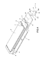
- FIG. 4 is a schematic in-use view illustrating the fastening device used for fastening stacked expansion cards
- FIG. 5 is a schematic view illustrating how to use the fastening device to fasten stacked expansion cards
- FIG. 6 is a schematic view illustrating applying a force to the fastening device.
- FIG. 7 is a cross-sectional view illustrating the fastening device after assembled.
- the present invention provides a fastening device 1 for stacking expansion cards 2 .
- the fastening device 1 is used to fasten at least one expansion card 2 to a circuit board 3 .
- a connector 4 is disposed on the circuit board 3 .
- One end of the expansion card 2 is inserted into the connector 4 , and the other end of the expansion card 2 is fastened to the circuit board 3 by means of the fastening device 1 .
- two connectors 4 , 4 ′ are disposed in a staggered manner on the circuit board 3 .
- Two expansion cards 2 , 2 ′ are inserted into the two connectors 4 , 4 ′, respectively, and are positioned on the circuit board 3 by the fastening device 1 .
- a detailed description of the fastening device 1 is provided as follows.
- the fastening device 1 includes a fastener 10 , a clamping member 20 and a connection band 30 .
- the fastener 10 and the clamping member 20 are connected by means of the connection band 30 .
- Two ends of the connection band 30 are connected to the fastener 10 and the clamping member 20 , respectively.
- the fastener 10 includes a body 11 , the body 11 includes a top portion 111 and a bottom portion 112 , a fastening hole 110 is formed on the top portion 111 along an axial direction, and a plurality of claws 113 are extended from the bottom portion 112 .
- the claw 113 is preferably an elastic arm.
- the clamping member 20 includes a clamping base 21 , a pin 22 connected to the clamping base 21 , a resilient element 23 in the clamping base 21 , and a push plate 24 driven by the resilient element 23 to move on the clamping base 21 .
- One end of the pin 22 protruding from the clamping base 21 , is inserted into the fastening hole 110 .
- the resilient element 23 is preferably a spring.
- the push plate 24 includes a push rib 241 at one side, and a top surface of the push rib 241 protrudes from a top surface of the push plate 24 .
- the push rib 241 facilitates gripping by a user to pull the push plate 24 .
- the clamping base 21 includes a reservation space 210 adjacent to the push rib 241 .
- the reservation space 210 is provided so that the push plate 24 can move on the clamping base 21 .
- connection band 30 is a bendable band. One end of the connection band 30 is connected to the fastener 10 , and the other end of the connection band 30 is connected to the clamping member 20 .
- the fastening device is constructed as mentioned above. The fastening device is in an integral form.
- the circuit board 3 includes at least one positioning hole 5 (also see FIG. 1 ).
- the fastener 10 is coupled to the circuit board 3 by inserting the claws 113 into the positioning hole 5 .
- a retaining recess 6 is formed at one side of the expansion card 2 , and the body 11 is shaped to match contours of the retaining recess 6 so as to be partially received in the retaining recess 6 .
- a pressing board 7 is formed in the retaining recess 6 of the expansion card 2
- the body 11 of the fastener 10 includes a platform 114 at one side of the fastening hole 110
- the pressing board 7 presses on the platform 114 in a manner such that a top surface of the pressing board 7 is flush with the top portion of the body 11 .
- the body 11 includes two blocking arms 115 at two sides of the platform 114 in order to position the pin 22 .
- the pin 22 is inserted in the fastening hole 110 of the fastener 10 .
- the two blocking arms 115 are in contact with the pin 22 at two sides thereof, so that the clamping member 20 is stably inserted in the fastener 10 .
- the clamping base 21 of the clamping member 20 includes a pressing surface 211 for pressing on the top surface of the pressing board 7 and the top portion of the body 11 , the pressing surface 211 is disposed at a bottom level of the pin 22 . Therefore, when the pin 22 is inserted in the fastening hole 110 , the pressing surface 211 presses on the top surface of the pressing board 7 and the top portion of the body 11 , and thereby one end of the expansion card 2 away from the connector 4 is positioned.
- FIG. 6 illustrating applying a force to the fastening device 1 and also refer to FIG. 7 for a cross-sectional view of the fastening device after assembled.
- a second connector 4 ′ for insertion of a second expansion card 2 ′ is disposed on the circuit board 3 .
- a retaining recess 6 ′ is formed at one side of the expansion card 2 ′, and a second pressing board 7 ′ is disposed in the retaining recess 6 ′.
- An accommodating recess 200 is formed at one end of the clamping base 21 of the clamping member 20 .
- the second pressing board 7 ′ is inserted in the accommodating recess 200 .
- a force is applied to the push rib 241 of the push plate 24 to push the push plate 24 in a direction away from the accommodating recess 200 to expose the accommodating recess 200 , so that the second pressing board 7 ′ of the second expansion card 2 ′ can be inserted in the accommodating recess 200 .
- the push plate 24 is restored to its original position by the elasticity of the resilient element, and one end of the push plate 24 presses on the second pressing board 7 ′ to position one end of the second expansion card 2 ′.
- One end of the second expansion card 2 ′ is inserted in the second connector 4 ′, and the other end of the second expansion card 2 ′ is fastened by means of the fastening device 1 .
- the second expansion card 2 ′ To remove the second expansion card 2 ′, a force applied to the push rib 241 to pull the push plate 24 , so that the push plate 24 is moved toward the reservation space 210 to be removed from the second pressing board 7 ′, thereby releasing the second expansion card 2 ′. Then, the second expansion card 2 ′ without being pressed by the push plate 24 can be detached from the second connector 4 ′.
- the fastening device 1 the two expansion cards 2 , 2 ′ can be inserted into the two connectors 4 and fastened to the circuit board 3 in a convenient and easy way.
Landscapes
- Engineering & Computer Science (AREA)
- Theoretical Computer Science (AREA)
- Microelectronics & Electronic Packaging (AREA)
- Power Engineering (AREA)
- Human Computer Interaction (AREA)
- Physics & Mathematics (AREA)
- General Engineering & Computer Science (AREA)
- General Physics & Mathematics (AREA)
- Computer Hardware Design (AREA)
- Coupling Device And Connection With Printed Circuit (AREA)
Abstract
A fastening device for stacking expansion cards includes a fastener, a clamping member and a connection band. The fastener includes a body, the body includes a top portion and a bottom portion opposite to each other. A fastening hole is formed on the top portion along an axial direction. Multiple claws are extended from the bottom portion. The clamping member includes a clamping base, a pin, a resilient element, and a push plate driven by the resilient element to move on the clamping base. One end of the pin protrudes from the clamping base to be inserted into the fastening hole. The connection band is bendable. One end of the connection band is connected to the fastener, and the other end of the connection band is connected to the clamping member. The fastening device can fasten stacked expansion cards to a circuit board.
Description
The present invention relates to a fastening device for an expansion card and, in particular, to a fastening device for stacking expansion cards.
Expansion cards are installed on a computer motherboard to add functionality of a computer system, such as Wi-Fi, bluetooth, the global positioning system (GPS), the near-field communication (NFC), the digital radio, the wireless gigabit alliance (WiGig), the wireless wide area network (WWAN), and a solid state drive (SSD). To fasten the expansion card, one end of the expansion card is inserted into a connector on a circuit board of a server. Then, the other end of the expansion card is fastened by screws, so that the expansion card can be fixed to the circuit board.
The expansion cards are usually installed in a single-layered manner on the circuit board. The single-layered expansion card is fastened by screws to the circuit board to prevent shifting of the expansion card to cause poor electrical connection or poor data transmission. A server needs to store a huge amount of data, and many expansion cards are used for data transmission and communication. However, if the expansion cards are disposed in a single-layered manner, they will take up too much space on the circuit board. In solution, the present invention provides a simple structure to stack the expansion cards vertically.
In view of this, the inventor studied various technologies and created an effective solution in the present disclosure.
It is an objective of the present invention to provide a fastening device for stacking expansion cards, so as to fasten stacked expansion cards.
Accordingly, the present invention provides a fastening device for stacking expansion cards. The fastening device includes a fastener, a clamping member and a connection band. The fastener includes a body. The body includes a top portion and a bottom portion opposite to each other, a fastening hole is formed on the top portion along an axial direction of the body, and a plurality of claws are extended from the bottom portion. The clamping member includes a clamping base, a pin, a resilient element, and a push plate driven by the resilient element to move on the clamping base. One end of the pin protrudes from the clamping base to be inserted into the fastening hole. The connection band is bendable, one end of the connection band is connected to the fastener, and the other end of the connection band is connected to the clamping member. By this configuration, the fastening device can fasten stacked expansion cards to a circuit board.
Compared to conventional techniques, the fastening device has the following features. The body of the fastener includes the fastening hole and the claws. The clamping member includes the clamping base, the pin, the resilient element, and the push plate driven by the resilient element to move on the clamping base. When the pin of the clamping member is inserted in the fastener, the clamping base of the clamping member presses on the expansion card and the fastener, thereby positioning one end of the expansion card away from a connector. An accommodating recess for insertion of one end of the expansion card is formed at one end of the clamping base. One end of the clamping member presses on the expansion card to position one end of the expansion card. By this way, the fastening device can fasten stacked expansion cards, thus improving practicability.
The disclosure will become more fully understood from the detailed description and the drawings given herein below for illustration only, and thus does not limit the disclosure, wherein:
Detailed descriptions and technical contents of the present disclosure are illustrated below in conjunction with the accompanying drawings. However, it is to be understood that the descriptions and the accompanying drawings disclosed herein are merely illustrative and exemplary and not intended to limit the scope of the present disclosure.
Referring to FIG. 1 , the present invention provides a fastening device 1 for stacking expansion cards 2. The fastening device 1 is used to fasten at least one expansion card 2 to a circuit board 3. A connector 4 is disposed on the circuit board 3. One end of the expansion card 2 is inserted into the connector 4, and the other end of the expansion card 2 is fastened to the circuit board 3 by means of the fastening device 1. In one embodiment of the present invention, two connectors 4, 4′ are disposed in a staggered manner on the circuit board 3. Two expansion cards 2, 2′ are inserted into the two connectors 4, 4′, respectively, and are positioned on the circuit board 3 by the fastening device 1. A detailed description of the fastening device 1 is provided as follows.
Please refer to FIGS. 2 and 3 for a perspective view and a side view of the fastening device 1. The fastening device 1 includes a fastener 10, a clamping member 20 and a connection band 30. The fastener 10 and the clamping member 20 are connected by means of the connection band 30. Two ends of the connection band 30 are connected to the fastener 10 and the clamping member 20, respectively.
The fastener 10 includes a body 11, the body 11 includes a top portion 111 and a bottom portion 112, a fastening hole 110 is formed on the top portion 111 along an axial direction, and a plurality of claws 113 are extended from the bottom portion 112. The claw 113 is preferably an elastic arm.
The clamping member 20 includes a clamping base 21, a pin 22 connected to the clamping base 21, a resilient element 23 in the clamping base 21, and a push plate 24 driven by the resilient element 23 to move on the clamping base 21. One end of the pin 22, protruding from the clamping base 21, is inserted into the fastening hole 110.
The resilient element 23 is preferably a spring. The push plate 24 includes a push rib 241 at one side, and a top surface of the push rib 241 protrudes from a top surface of the push plate 24. The push rib 241 facilitates gripping by a user to pull the push plate 24. Preferably, the clamping base 21 includes a reservation space 210 adjacent to the push rib 241. The reservation space 210 is provided so that the push plate 24 can move on the clamping base 21.
The connection band 30 is a bendable band. One end of the connection band 30 is connected to the fastener 10, and the other end of the connection band 30 is connected to the clamping member 20. The fastening device is constructed as mentioned above. The fastening device is in an integral form.
Please refer to FIGS. 4 and 5 illustrating the fastening device 1 in use and how to use it. In the present embodiment, the circuit board 3 includes at least one positioning hole 5 (also see FIG. 1 ). The fastener 10 is coupled to the circuit board 3 by inserting the claws 113 into the positioning hole 5. A retaining recess 6 is formed at one side of the expansion card 2, and the body 11 is shaped to match contours of the retaining recess 6 so as to be partially received in the retaining recess 6.
In detail, a pressing board 7 is formed in the retaining recess 6 of the expansion card 2, the body 11 of the fastener 10 includes a platform 114 at one side of the fastening hole 110, and the pressing board 7 presses on the platform 114 in a manner such that a top surface of the pressing board 7 is flush with the top portion of the body 11. It is preferable that the body 11 includes two blocking arms 115 at two sides of the platform 114 in order to position the pin 22.
When the clamping member 20 is moved toward the fastener 10 by bending the connection band 30, the pin 22 is inserted in the fastening hole 110 of the fastener 10. When the pin 22 is inserted in the fastening hole 110, the two blocking arms 115 are in contact with the pin 22 at two sides thereof, so that the clamping member 20 is stably inserted in the fastener 10.
It should be noted that, the clamping base 21 of the clamping member 20 includes a pressing surface 211 for pressing on the top surface of the pressing board 7 and the top portion of the body 11, the pressing surface 211 is disposed at a bottom level of the pin 22. Therefore, when the pin 22 is inserted in the fastening hole 110, the pressing surface 211 presses on the top surface of the pressing board 7 and the top portion of the body 11, and thereby one end of the expansion card 2 away from the connector 4 is positioned.
Please refer to FIG. 6 illustrating applying a force to the fastening device 1 and also refer to FIG. 7 for a cross-sectional view of the fastening device after assembled. In the present embodiment, a second connector 4′ for insertion of a second expansion card 2′ is disposed on the circuit board 3. A retaining recess 6′ is formed at one side of the expansion card 2′, and a second pressing board 7′ is disposed in the retaining recess 6′.
An accommodating recess 200 is formed at one end of the clamping base 21 of the clamping member 20. The second pressing board 7′ is inserted in the accommodating recess 200.
To fasten the other expansion card 2′ by the fastening device 1, a force is applied to the push rib 241 of the push plate 24 to push the push plate 24 in a direction away from the accommodating recess 200 to expose the accommodating recess 200, so that the second pressing board 7′ of the second expansion card 2′ can be inserted in the accommodating recess 200. When no external force is applied to the push plate 241, the push plate 24 is restored to its original position by the elasticity of the resilient element, and one end of the push plate 24 presses on the second pressing board 7′ to position one end of the second expansion card 2′. One end of the second expansion card 2′ is inserted in the second connector 4′, and the other end of the second expansion card 2′ is fastened by means of the fastening device 1.
To remove the second expansion card 2′, a force applied to the push rib 241 to pull the push plate 24, so that the push plate 24 is moved toward the reservation space 210 to be removed from the second pressing board 7′, thereby releasing the second expansion card 2′. Then, the second expansion card 2′ without being pressed by the push plate 24 can be detached from the second connector 4′. By using the fastening device 1, the two expansion cards 2, 2′ can be inserted into the two connectors 4 and fastened to the circuit board 3 in a convenient and easy way.
It is to be understood that the above descriptions are merely the preferable embodiment of the present invention and are not intended to limit the scope of the present invention. Equivalent changes and modifications made in the spirit of the present invention are regarded as falling within the scope of the present invention.
Claims (10)
1. A fastening device for stacking expansion cards, for fastening at least one expansion card to a circuit board, at least one connector being disposed on the circuit board, one end of the expansion card being inserted into the connector, the fastening device comprising:
a fastener including a body, the body including a top portion and a bottom portion opposite to each other, a fastening hole being formed on the top portion along an axial direction of the body, a plurality of claws being extended from the bottom portion;
a clamping member, the clamping member including a clamping base, a pin connected to the clamping base, a resilient element in the clamping base, and a push plate driven by the resilient element to move on the clamping base, one end of the pin protruding from the clamping base to be inserted into the fastening hole; and
a connection band, the connection band being bendable, one end of the connection band being connected to the fastener, the other end of the connection band being connected to the clamping member.
2. The fastening device for stacking the expansion cards according to claim 1 , wherein a retaining recess is formed at one side of the expansion card, and the body is shaped to match contours of the retaining recess so as to be partially received in the retaining recess.
3. The fastening device for stacking the expansion cards according to claim 2 , wherein a pressing board is formed in the retaining recess of the expansion card, the body includes a platform at one side of the fastening hole, and the pressing board presses on the platform in a manner such that a top surface of the pressing board is flush with the top portion of the body.
4. The fastening device for stacking the expansion cards according to claim 3 , wherein the clamping base includes a pressing surface for pressing on a top surface of the pressing board and the top portion of the body, and the pressing surface is disposed at a bottom level of the pin.
5. The fastening device for stacking the expansion cards according to claim 3 , wherein the body includes two blocking arms at two sides of the platform.
6. The fastening device for stacking the expansion cards according to claim 1 , wherein the circuit board includes at least one positioning hole, and the fastener is coupled to the circuit board by inserting the claws into the positioning hole.
7. The fastening device for stacking the expansion cards according to claim 1 , wherein the push plate includes a push rib at one side, and a top surface of the push rib protrudes from a top surface of the push plate.
8. The fastening device for stacking the expansion cards according to claim 7 , wherein the clamping base includes a reservation space adjacent to the push rib.
9. The fastening device for stacking the expansion cards according to claim 1 , wherein the resilient element is a spring.
10. The fastening device for stacking the expansion cards according to claim 1 , wherein a second connector for insertion of the second expansion card is disposed on the circuit board, a second retaining recess is formed at one side of the second expansion card, a second pressing board is disposed in the second retaining recess, and an accommodating recess is formed at one end of the clamping base; when the push plate is pushed to move in a direction away from the accommodating recess to expose the accommodating recess, the second pressing board is allowed to be inserted in the accommodating recess; when no external force is applied to the push plate, the push plate is restored to its original position by the elasticity of the resilient element and presses on the second pressing board.
Priority Applications (3)
| Application Number | Priority Date | Filing Date | Title |
|---|---|---|---|
| US15/984,412 US10264694B1 (en) | 2018-05-20 | 2018-05-20 | Fastening device for stacking expansion cards |
| TW107207997U TWM573850U (en) | 2018-05-20 | 2018-06-14 | Multi-layer expansion card holder |
| CN201820969498.6U CN208569479U (en) | 2018-05-20 | 2018-06-22 | The fixator of multilayer expansion board |
Applications Claiming Priority (1)
| Application Number | Priority Date | Filing Date | Title |
|---|---|---|---|
| US15/984,412 US10264694B1 (en) | 2018-05-20 | 2018-05-20 | Fastening device for stacking expansion cards |
Publications (1)
| Publication Number | Publication Date |
|---|---|
| US10264694B1 true US10264694B1 (en) | 2019-04-16 |
Family
ID=65487923
Family Applications (1)
| Application Number | Title | Priority Date | Filing Date |
|---|---|---|---|
| US15/984,412 Active US10264694B1 (en) | 2018-05-20 | 2018-05-20 | Fastening device for stacking expansion cards |
Country Status (3)
| Country | Link |
|---|---|
| US (1) | US10264694B1 (en) |
| CN (1) | CN208569479U (en) |
| TW (1) | TWM573850U (en) |
Cited By (8)
| Publication number | Priority date | Publication date | Assignee | Title |
|---|---|---|---|---|
| US10790602B2 (en) * | 2018-10-22 | 2020-09-29 | Weidmüller Interface GmbH & Co. KG | Electrical connector for connecting electrical conductors to a printed circuit board |
| US10806050B1 (en) * | 2019-09-24 | 2020-10-13 | Yao-Fang Chou | Solid-state drive adapter card |
| US11102913B2 (en) * | 2020-01-20 | 2021-08-24 | Giga-Byte Technology Co., Ltd. | Heat dissipating assembly and main board module |
| US20220141984A1 (en) * | 2020-10-29 | 2022-05-05 | Acer Incorporated | Positioning structure |
| US11552415B2 (en) * | 2020-07-23 | 2023-01-10 | Quanta Computer Inc. | Retainer for securing a connection |
| DE102021127209A1 (en) | 2021-10-20 | 2023-04-20 | Fujitsu Client Computing Limited | Circuit board, computer assembly and connector |
| US20230235771A1 (en) * | 2022-01-27 | 2023-07-27 | Fivetech Technology Inc. | Fastening device |
| US20240030635A1 (en) * | 2022-07-19 | 2024-01-25 | Dell Products L.P. | Method for pre-assembly of compression attached memory modules |
Families Citing this family (1)
| Publication number | Priority date | Publication date | Assignee | Title |
|---|---|---|---|---|
| CN115657796B (en) * | 2022-09-23 | 2025-12-19 | 环旭电子股份有限公司 | Fixing component for solid state disk |
Citations (7)
| Publication number | Priority date | Publication date | Assignee | Title |
|---|---|---|---|---|
| US20100033942A1 (en) * | 2008-08-07 | 2010-02-11 | Chih-Ching Yang | Supporting structure and electronic device using the same |
| US20100195304A1 (en) * | 2007-10-15 | 2010-08-05 | Fujitsu Limited | Printed circuit board unit and electronic apparatus |
| US20110249419A1 (en) * | 2010-04-07 | 2011-10-13 | Hon Hai Precision Industry Co., Ltd. | Circuit board assembly and connecting bracket thereof |
| US8085552B2 (en) * | 2008-12-26 | 2011-12-27 | Fujitsu Limited | Attachment device and electronic apparatus |
| US20160268713A1 (en) * | 2013-12-19 | 2016-09-15 | Hewlett Packard Enterprise Development Lp | Connector to secure asolid state device in an off motherboard location |
| US9468123B2 (en) * | 2014-09-25 | 2016-10-11 | Wistron Corporation | Electronic device with quick releasing function for an interface card |
| US10101523B1 (en) * | 2018-01-30 | 2018-10-16 | Giga-Byte Technology Co., Ltd. | Light guide heat dissipation module and electronic device |
-
2018
- 2018-05-20 US US15/984,412 patent/US10264694B1/en active Active
- 2018-06-14 TW TW107207997U patent/TWM573850U/en unknown
- 2018-06-22 CN CN201820969498.6U patent/CN208569479U/en active Active
Patent Citations (7)
| Publication number | Priority date | Publication date | Assignee | Title |
|---|---|---|---|---|
| US20100195304A1 (en) * | 2007-10-15 | 2010-08-05 | Fujitsu Limited | Printed circuit board unit and electronic apparatus |
| US20100033942A1 (en) * | 2008-08-07 | 2010-02-11 | Chih-Ching Yang | Supporting structure and electronic device using the same |
| US8085552B2 (en) * | 2008-12-26 | 2011-12-27 | Fujitsu Limited | Attachment device and electronic apparatus |
| US20110249419A1 (en) * | 2010-04-07 | 2011-10-13 | Hon Hai Precision Industry Co., Ltd. | Circuit board assembly and connecting bracket thereof |
| US20160268713A1 (en) * | 2013-12-19 | 2016-09-15 | Hewlett Packard Enterprise Development Lp | Connector to secure asolid state device in an off motherboard location |
| US9468123B2 (en) * | 2014-09-25 | 2016-10-11 | Wistron Corporation | Electronic device with quick releasing function for an interface card |
| US10101523B1 (en) * | 2018-01-30 | 2018-10-16 | Giga-Byte Technology Co., Ltd. | Light guide heat dissipation module and electronic device |
Cited By (13)
| Publication number | Priority date | Publication date | Assignee | Title |
|---|---|---|---|---|
| US10790602B2 (en) * | 2018-10-22 | 2020-09-29 | Weidmüller Interface GmbH & Co. KG | Electrical connector for connecting electrical conductors to a printed circuit board |
| US10806050B1 (en) * | 2019-09-24 | 2020-10-13 | Yao-Fang Chou | Solid-state drive adapter card |
| US11102913B2 (en) * | 2020-01-20 | 2021-08-24 | Giga-Byte Technology Co., Ltd. | Heat dissipating assembly and main board module |
| US11552415B2 (en) * | 2020-07-23 | 2023-01-10 | Quanta Computer Inc. | Retainer for securing a connection |
| US20220141984A1 (en) * | 2020-10-29 | 2022-05-05 | Acer Incorporated | Positioning structure |
| US11706888B2 (en) * | 2020-10-29 | 2023-07-18 | Acer Incorporated | Positioning structure |
| JP2023061919A (en) * | 2021-10-20 | 2023-05-02 | 富士通クライアントコンピューティング株式会社 | Circuit board, computer device, and connection device |
| DE102021127209A1 (en) | 2021-10-20 | 2023-04-20 | Fujitsu Client Computing Limited | Circuit board, computer assembly and connector |
| GB2615382A (en) * | 2021-10-20 | 2023-08-09 | Fujitsu Client Computing Ltd | Circuit board, computer device, and connecting device |
| GB2615382B (en) * | 2021-10-20 | 2024-01-24 | Fujitsu Client Computing Ltd | Circuit board, computer device, and connecting device |
| US20230235771A1 (en) * | 2022-01-27 | 2023-07-27 | Fivetech Technology Inc. | Fastening device |
| US20240030635A1 (en) * | 2022-07-19 | 2024-01-25 | Dell Products L.P. | Method for pre-assembly of compression attached memory modules |
| US12424777B2 (en) * | 2022-07-19 | 2025-09-23 | Dell Products L.P. | Method for pre-assembly of compression attached memory modules |
Also Published As
| Publication number | Publication date |
|---|---|
| TWM573850U (en) | 2019-02-01 |
| CN208569479U (en) | 2019-03-01 |
Similar Documents
| Publication | Publication Date | Title |
|---|---|---|
| US10264694B1 (en) | Fastening device for stacking expansion cards | |
| US8657619B2 (en) | Fixing mechanism for fixing a board and electronic device therewith | |
| US20150044913A1 (en) | Wire-to-board connector assembly and board-end connector thereof | |
| US20140154926A1 (en) | Electronic card connector and electronic device using the same | |
| US20140185199A1 (en) | Electronic device with releasable card holder | |
| CN104063027B (en) | Electronic installation | |
| US8432682B2 (en) | Electronic device with slot cover ejection mechanism | |
| US20120228001A1 (en) | Cable management apparatus | |
| US8986025B2 (en) | Plug device for connectors | |
| US6942514B1 (en) | Quick release connector for connecting terminal board | |
| US20160178856A1 (en) | Engaging assembly for small form-factor pluggable transceiver | |
| US9213921B2 (en) | Electronic card connector and electronic device using the same | |
| CN104600490B (en) | Mobile terminal with fixing device | |
| CN107807723B (en) | Mainboard assembly and fastening device thereof | |
| CN111459238A (en) | Cabinet | |
| US20140141642A1 (en) | Electronic card connector and electronic device using the same | |
| US20160098067A1 (en) | Electronic card holder and electronic device using same | |
| US8777645B2 (en) | Card accommodating and ejecting device | |
| US9648156B2 (en) | Terminal docking device | |
| US8873229B2 (en) | Electronic device having card holder | |
| CN103296563A (en) | Card Mounting Device | |
| US9209564B2 (en) | Card connector | |
| WO2016023334A1 (en) | Connector base, connector assembly, and network device using connector assembly | |
| US20080311784A1 (en) | Connecting and releasing apparatus for a connector | |
| US20200366330A1 (en) | Clamping devices for intelligent mobile terminal |
Legal Events
| Date | Code | Title | Description |
|---|---|---|---|
| FEPP | Fee payment procedure |
Free format text: ENTITY STATUS SET TO UNDISCOUNTED (ORIGINAL EVENT CODE: BIG.); ENTITY STATUS OF PATENT OWNER: LARGE ENTITY |
|
| STCF | Information on status: patent grant |
Free format text: PATENTED CASE |
|
| MAFP | Maintenance fee payment |
Free format text: PAYMENT OF MAINTENANCE FEE, 4TH YEAR, LARGE ENTITY (ORIGINAL EVENT CODE: M1551); ENTITY STATUS OF PATENT OWNER: LARGE ENTITY Year of fee payment: 4 |