US1026079A - Stabilizing lifting-plane for flying-machines. - Google Patents
Stabilizing lifting-plane for flying-machines. Download PDFInfo
- Publication number
- US1026079A US1026079A US64777611A US1911647776A US1026079A US 1026079 A US1026079 A US 1026079A US 64777611 A US64777611 A US 64777611A US 1911647776 A US1911647776 A US 1911647776A US 1026079 A US1026079 A US 1026079A
- Authority
- US
- United States
- Prior art keywords
- plane
- bellows
- lifting
- flying
- machines
- Prior art date
- Legal status (The legal status is an assumption and is not a legal conclusion. Google has not performed a legal analysis and makes no representation as to the accuracy of the status listed.)
- Expired - Lifetime
Links
- 230000000087 stabilizing effect Effects 0.000 title description 4
- 238000007598 dipping method Methods 0.000 description 1
- 239000004744 fabric Substances 0.000 description 1
Images
Classifications
-
- B—PERFORMING OPERATIONS; TRANSPORTING
- B64—AIRCRAFT; AVIATION; COSMONAUTICS
- B64C—AEROPLANES; HELICOPTERS
- B64C13/00—Control systems or transmitting systems for actuating flying-control surfaces, lift-increasing flaps, air brakes, or spoilers
- B64C13/24—Transmitting means
Definitions
- This desirable result is accomplished by providing the flying machine with a partly inflated'lift-ing plane constructed somewhat like the body portion of a pair of bellows and extending across the machine so that excessive pressure agalnst'the under side of one portion of said bellows-like, plane will change the angle of the under surface of said portion to diminish the lifting power thereof, the air in said portion being forced to a portion of the bellows-like plane on the other side of the machine so as to form a lifting plane of greater angle at the latter side of the machine, time effecting lateral balancing of the machine.
- Stabilizing with a view to preventing excessive inclination to the front or rear is obtained by reason of the bellows-shaped lifting plane automatically conforming its lower side to the varying air pressure in such a manner as to right the machine from any dangerous dips upon which it may start to enter.
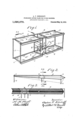
- Figure 1 is a perspective view of the front portion of an aeroplane showing the same provided with two lifting planes constructed according to the princi-- ples of this invention
- Fig. 2 is a cross section of the upper lifting plane on line as of Fig. 1
- Fig. 3 is an enlarged broken cross section on line m of Fig.
- Fig. 1 my newly inventedlifting planes 1 and 2 are shown in Fig. 1 mounted respectively in the upper and the lower portions of the frame 3 of an aeroplane of the biplane type. It is to be understood, however, that the 1nvention is not limited to use upon biplanes but may be applied to other types of flying machines including lifting planes of any character. v
- the upper plane 1 and lower plane 2 are similarly constructed and therefore only one need be described in detail.
- the upper lifting plane consists of a plurality of bellowsshaped sections 4 and 5 and the lower lifting plane likewise consists of the bellows sections 6 and 7.
- the bellows-sha d sections l and 5 are similarly constructed, the polnted portion of the bellows being forward.
- Each bellows section is desirably maintained in about a half inflated condition.
- Said bellows sections are connected with each other by a runway 8 large enough to permit excessive air pressure upon the underside of one bellows to be quickly communicated to the bellows at the other side.
- An inflating tube 9 provided with a valve 11 affords means to inflate the lifting planes or to deflate the same if desired, said tube communicating with a tube 12 which connects the runway 8 of the upper plane with the runway 8 of the lower plane. Said tube 12 will equalize the air pressure between the bellows sections of the upper plane and those of the lower plane because said runways 8 are in communication with the bellows sections of said planes.
- each plane permits the bellows sections on each side to operate independently to equalize automatically the lifting power of the atmosphere on opposite sides of the mid-width of the machine. This result is attained by reason of the bellows sections of said plane containing air which may flow freely from one side to the'other through'said neck or runway 8.
- a flying machine provided with a transverse lifting plane, said plane consisting of the bottom walls of two communicating bellows, and a contracted neck connecting said bellows, the deflation of one of said bellows causing the inflation of the other.
- f1 flying machine provided with two superposed transverse lifting planes, said planes each consisting of the bottom walls of a set of two communicating bellows, a horizontal way or conduit afl'ording communication between the bellows of each set, and another conduit to afford atmospheric communication between said horizontal conduits and thereby place all of said bellows in atmospheric communication with each other.
Landscapes
- Engineering & Computer Science (AREA)
- Automation & Control Theory (AREA)
- Aviation & Aerospace Engineering (AREA)
- Toys (AREA)
Description
A. P. DIERDORFP.
STABILIZING LII-TING PLANE FOR FLYING MAOHIHES.
APPLICATION FILED SEPT. 5, 1911.
Patented May 14, 1912.
wit/7653a:
ANUMW Ii. DIERDOR'FF,
or Los ANGELES,
CALIFORNIA.
STABILIZING LIFTING-PLANE FOR FLYING-MACHINES.
Specification of Letters Patent.
Patented May 14, 1912.
Application filed September 5, 1911. Serial No. 647,776.
excessive or dangerous inclination of the machine in any direction. This desirable result is accomplished by providing the flying machine with a partly inflated'lift-ing plane constructed somewhat like the body portion of a pair of bellows and extending across the machine so that excessive pressure agalnst'the under side of one portion of said bellows-like, plane will change the angle of the under surface of said portion to diminish the lifting power thereof, the air in said portion being forced to a portion of the bellows-like plane on the other side of the machine so as to form a lifting plane of greater angle at the latter side of the machine, time effecting lateral balancing of the machine.
Stabilizing with a view to preventing excessive inclination to the front or rear is obtained by reason of the bellows-shaped lifting plane automatically conforming its lower side to the varying air pressure in such a manner as to right the machine from any dangerous dips upon which it may start to enter.
Referring to the accompanying drawings which illustrate the preferred embodiment of the invention, Figure 1 is a perspective view of the front portion of an aeroplane showing the same provided with two lifting planes constructed according to the princi-- ples of this invention; Fig. 2 is a cross section of the upper lifting plane on line as of Fig. 1; Fig. 3 is an enlarged broken cross section on line m of Fig.
Referring in detail to the drawings, my newly inventedlifting planes 1 and 2 are shown in Fig. 1 mounted respectively in the upper and the lower portions of the frame 3 of an aeroplane of the biplane type. It is to be understood, however, that the 1nvention is not limited to use upon biplanes but may be applied to other types of flying machines including lifting planes of any character. v
The upper plane 1 and lower plane 2 are similarly constructed and therefore only one need be described in detail. The upper lifting plane consists of a plurality of bellowsshaped sections 4 and 5 and the lower lifting plane likewise consists of the bellows sections 6 and 7. The bellows-sha d sections l and 5 are similarly constructed, the polnted portion of the bellows being forward. Each bellows section is desirably maintained in about a half inflated condition. Said bellows sections are connected with each other by a runway 8 large enough to permit excessive air pressure upon the underside of one bellows to be quickly communicated to the bellows at the other side. This feature is what is relied upon to stabilize themachine against one wing or the other dipping too much toward the earth These bellows'shaped lifting planes will be formed of any suitable air-tight fabric and will be somewhat flexible upon the under side so that the air pressure will tend to make the center portion (from front to rear) of thelower surface of the bellows curve upwardly and thus assume the character of curve which has been scientifically proved to afford the best lifting power.
An inflating tube 9 provided with a valve 11 affords means to inflate the lifting planes or to deflate the same if desired, said tube communicating with a tube 12 which connects the runway 8 of the upper plane with the runway 8 of the lower plane. Said tube 12 will equalize the air pressure between the bellows sections of the upper plane and those of the lower plane because said runways 8 are in communication with the bellows sections of said planes.
14 is the usual propeller.
The contracted neck 8 of each plane permits the bellows sections on each side to operate independently to equalize automatically the lifting power of the atmosphere on opposite sides of the mid-width of the machine. This result is attained by reason of the bellows sections of said plane containing air which may flow freely from one side to the'other through'said neck or runway 8.
In operation, if an air current strike with unusual force against the under side of the bellows at one side of the machine, a de- Qflating movement of said bellows will take place, lessening the angle of incidence of the lower surface thereof and therefore lessening the lifting power of the atmos 5 phere at that side. At the same time, more Q of a more or less wedge shape form, but
am not aware that an air-filled container has as yet been devised so constructed that it could properly be called a bellows and adapted to perform the function of a lifting plane. V
I claim:
1. In a flying-machine, a bellows-shaped lifting plane on each side of the machine, each of said planes containing air, and
means affording atmospheric communication between the chambers of said planes to permit the pressure of the outer air against the under side of one of the planes to automatically force air into the chamber of the other plane to change the angle of in icidence of the under side thereof.
2. A flying machine provided with a transverse lifting plane, said plane consisting of the bottom walls of two communicating bellows, and a contracted neck connecting said bellows, the deflation of one of said bellows causing the inflation of the other.
3. f1 flying machine provided with two superposed transverse lifting planes, said planes each consisting of the bottom walls of a set of two communicating bellows, a horizontal way or conduit afl'ording communication between the bellows of each set, and another conduit to afford atmospheric communication between said horizontal conduits and thereby place all of said bellows in atmospheric communication with each other.
In testimony whereof I have hereunto signed my name in the presence of two subscribing witnesses at Los Angeles, in the county of Los Angeles and State of Cali- "fornia; this 31st day of August 1911.
ANDREW F. DIERDORFF.
Witnesses:
ALBERT H. MERRILL, LILLIAN YOUNG.
Copies of this patent maybe obtained for five cents each, by addressing the Commissioner qt Patents,
Washington, I). C, 1
Priority Applications (1)
| Application Number | Priority Date | Filing Date | Title |
|---|---|---|---|
| US64777611A US1026079A (en) | 1911-09-05 | 1911-09-05 | Stabilizing lifting-plane for flying-machines. |
Applications Claiming Priority (1)
| Application Number | Priority Date | Filing Date | Title |
|---|---|---|---|
| US64777611A US1026079A (en) | 1911-09-05 | 1911-09-05 | Stabilizing lifting-plane for flying-machines. |
Publications (1)
| Publication Number | Publication Date |
|---|---|
| US1026079A true US1026079A (en) | 1912-05-14 |
Family
ID=3094374
Family Applications (1)
| Application Number | Title | Priority Date | Filing Date |
|---|---|---|---|
| US64777611A Expired - Lifetime US1026079A (en) | 1911-09-05 | 1911-09-05 | Stabilizing lifting-plane for flying-machines. |
Country Status (1)
| Country | Link |
|---|---|
| US (1) | US1026079A (en) |
-
1911
- 1911-09-05 US US64777611A patent/US1026079A/en not_active Expired - Lifetime
Similar Documents
| Publication | Publication Date | Title |
|---|---|---|
| ES2256558T3 (en) | AIRCRAFT LIGHTER THAN THE AIR PROVIDED WITH LANDING TRAIN MEDIA WITH AIR DAMPING. | |
| US1027590A (en) | Dirigible airship. | |
| US2120250A (en) | Aerofoil | |
| US1523994A (en) | Flying machine | |
| US1290669A (en) | Aeronautical apparatus. | |
| US1106020A (en) | Aeroplane. | |
| US1104242A (en) | Airship. | |
| US3618877A (en) | Flexible tail aircraft | |
| US3375894A (en) | Flexible skirt components for air cushion vehicles | |
| US1190397A (en) | Airship. | |
| US1049498A (en) | Flying or soaring machine. | |
| US1112615A (en) | Air-craft. | |
| US1034257A (en) | Aeroplane. | |
| US1879857A (en) | Aircraft | |
| US152414A (en) | Improvement in aerial boats | |
| US1021496A (en) | Flying-machine. | |
| US1172182A (en) | Flying-machine. | |
| US1084068A (en) | Lifting-surface for flying-machines. | |
| US784161A (en) | Air-ship. | |
| US1199215A (en) | Flying-machine. | |
| US1124917A (en) | Aeroplane construction. | |
| US1325920A (en) | Aeroplane | |
| US1653902A (en) | Aircraft | |
| US1284373A (en) | Aeroplane. | |
| US1084552A (en) | Flying-machine. |